Skyrc i-meter User manual

INSTRUCTION MANUAL
Multimeter 7 in 1
www.skyrc.com- 01 -
www.skyrc.com - 02 -
TABLE OF CONTENTS
Introduction 03
Features 04
Set Contents 04
Battery Checker 06
Battery Internal Resistance 08
Watt Meter 10
Servo Tester 12
Tacheometer RPM 13
Temperature 14
Thrust Calculator 15
Product Specifications 16
Warranty And Service 16
TABLE OF CONTENTS
CAUTION - Before you start
This is a sophisticated unit which will be an important tool in your
electric powered model program. Please be careful with it! And please
read this instruction manual thoroughly before operating.
There are risks associated with the potentially high currents measured
by the i-Meter. These include, but are not limited to, fire, burns and
personal injury. The user must be familiar with the relevant methods,
procedures and connection components before using or making any
connection.
High power electrical systems pose dangers independent of devices
like the i-Meter and it is the user's responsibility to be familiar with these
dangers and take any necessary action to ensure safe use. Shorting a
rechargeable battery or a i-Meter connected to a rechargeable battery
or battery charger can supply huge currents and have serious
consequences including explosions, causing fire, damage to equipment
and personal injury.
Do not exceed a maximum of 60 volts for the main power pack (MPP)
Keep proper distance from propeller during measurement process.
Keep the i-Meter well away from dirt or water.
Do not disassemble, modify or subject the unit to force impact.

INTRODUCTION
Thank you for the purchase of this SKYRC i-Meter. The SkyRC i-Meter
can carry out an enormous range of functions related to Electric
Powered models and has been designed with ease of use as a prime
objective. This Instruction Manual describes the scope of i-Meter and
how to make it work for you.
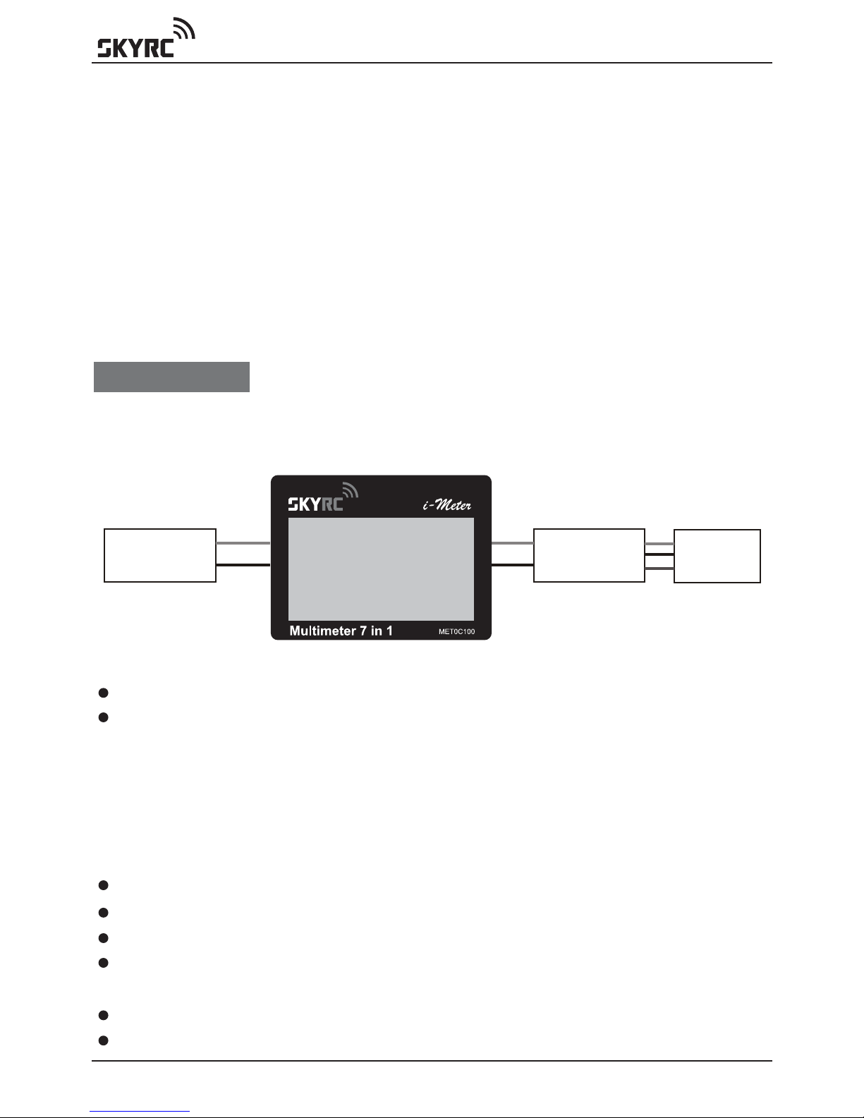
Input
Voltage
Port LCD Display
Dot Matrix 128*64
Connector to
Temperature
Sensor Probe
Connector to
Servo
Potentiometer Dial
to Control Servos,
ESC, other PW devices
Optical
Tachometer
Sensor
Output
Mode
Back
ESC
Enter
www.skyrc.com- 03 -
INTRODUCTION

www.skyrc.com - 04 -
FEATURES
SET CONTENTS
FEATURES
1. Battery Checker
2. Battery Internal Resistance
3. Watt Meter
4. Servo Tester
5. Optical Tachometer
6. Temperature Gauge
7. Thrust Calculator
1. Input Cable
2. Battery Internal Resistance Cable
3. i-Meter
4. Temperature Probe
5. Output Cable
13
4
5
2

www.skyrc.com- 05 -
FEATURES
MODE
MODE
MODE MODE
MODE
MODE
MODE
MODE
BATTERY CHECKER
INT.RESISTANCE
WATT METER
SERVO TESTER
TACHOMETER RPM
TEMPERATURE
THRUST CALC...
SET UP
BATTERY CHECKER
INT.RESISTANCE
WATT METER
SERVO TESTER
TACHOMETER RPM
TEMPERATURE
THRUST CALC...
SET UP
BATTERY CHECKER
INT.RESISTANCE
WATT METER
SERVO TESTER
TACHOMETER RPM
TEMPERATURE
THRUST CALC...
SET UP
BATTERY CHECKER
INT.RESISTANCE
WATT METER
SERVO TESTER
TACHOMETER RPM
TEMPERATURE
THRUST CALC...
SET UP
BATTERY CHECKER
INT.RESISTANCE
WATT METER
SERVO TESTER
TACHOMETER RPM
TEMPERATURE
THRUST CALC...
SET UP
BATTERY CHECKER
INT.RESISTANCE
WATT METER
SERVO TESTER
TACHOMETER RPM
TEMPERATURE
THRUST CALC...
SET UP
BATTERY CHECKER
INT.RESISTANCE
WATT METER
SERVO TESTER
TACHOMETER RPM
TEMPERATURE
THRUST CALC...
SET UP
BATTERY CHECKER
INT.RESISTANCE
WATT METER
SERVO TESTER
TACHOMETER RPM
TEMPERATURE
THRUST CALC...
SET UP
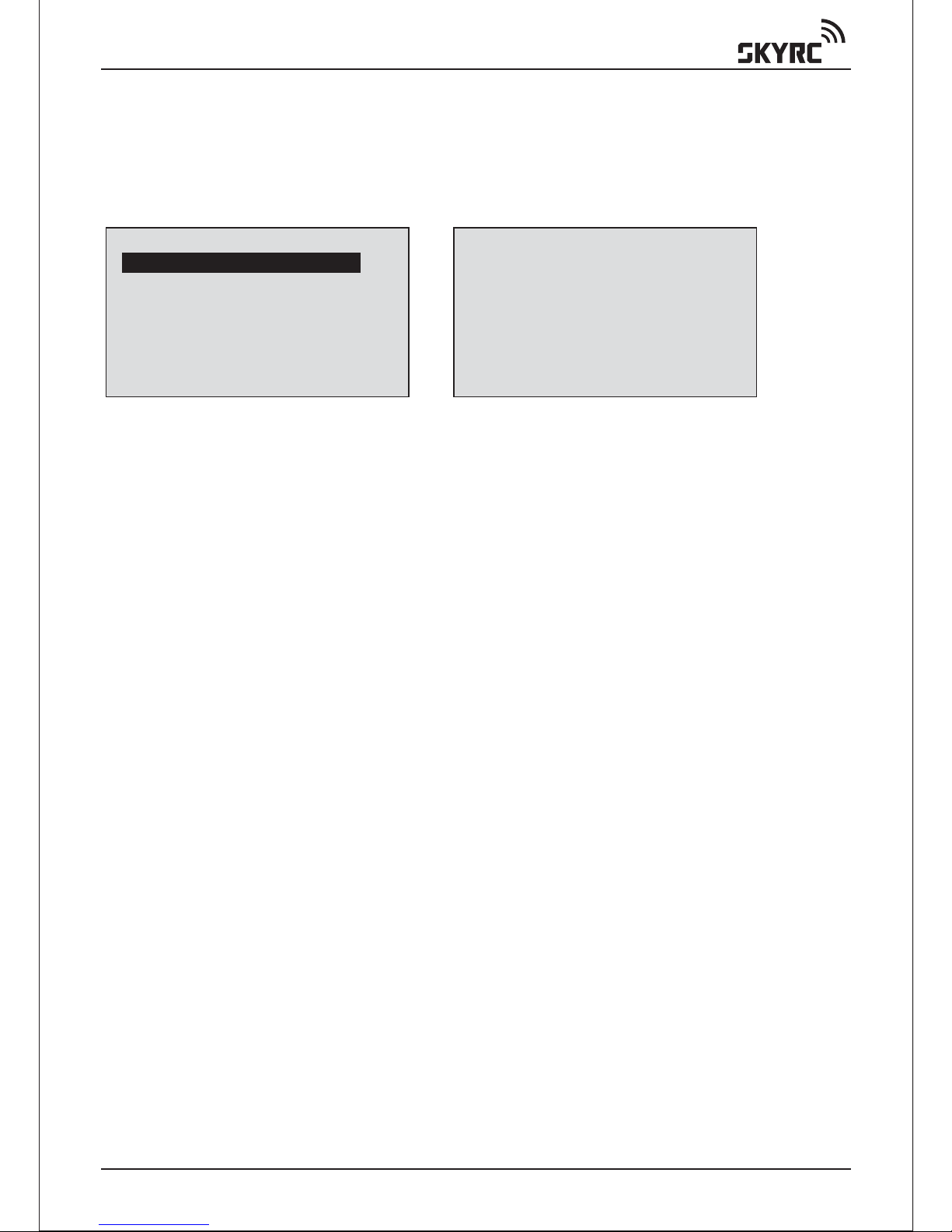
The Main screen displays all the available functions. The desired
function can be accessed by highlighting the desired function by
pressing ‘MODE’ button, pressing the ‘ENTER’ button to select
that function.
www.skyrc.com - 06 -
BATTERY CHECKER
BATTERY CHECKER
The i-Meter allows you to check the individual cell voltages of a 2 cells-
8 cells Lithium battery. The i-Meter individually measures & diagnoses
the cell voltages of the multiple cells, the result is displayed on the
large liquid crystal screen. The i-Meter replaces all of the tedious
measurement and calculations required in the past to determine the
overall voltage of the LiPo, LiFe & LiIon pack and the individual cell
voltages that determine the balance of the Lithium pack.
The i-Meter now makes it possible to determine and verify the detailed
state of the Lithium battery.
A balanced battery provides a safer environment when flying. If you
know that your cell balance is out you can address the issue.
The prevention of deteriorating cells over time, will improve the
efficiency and stability of the Lithium battery.
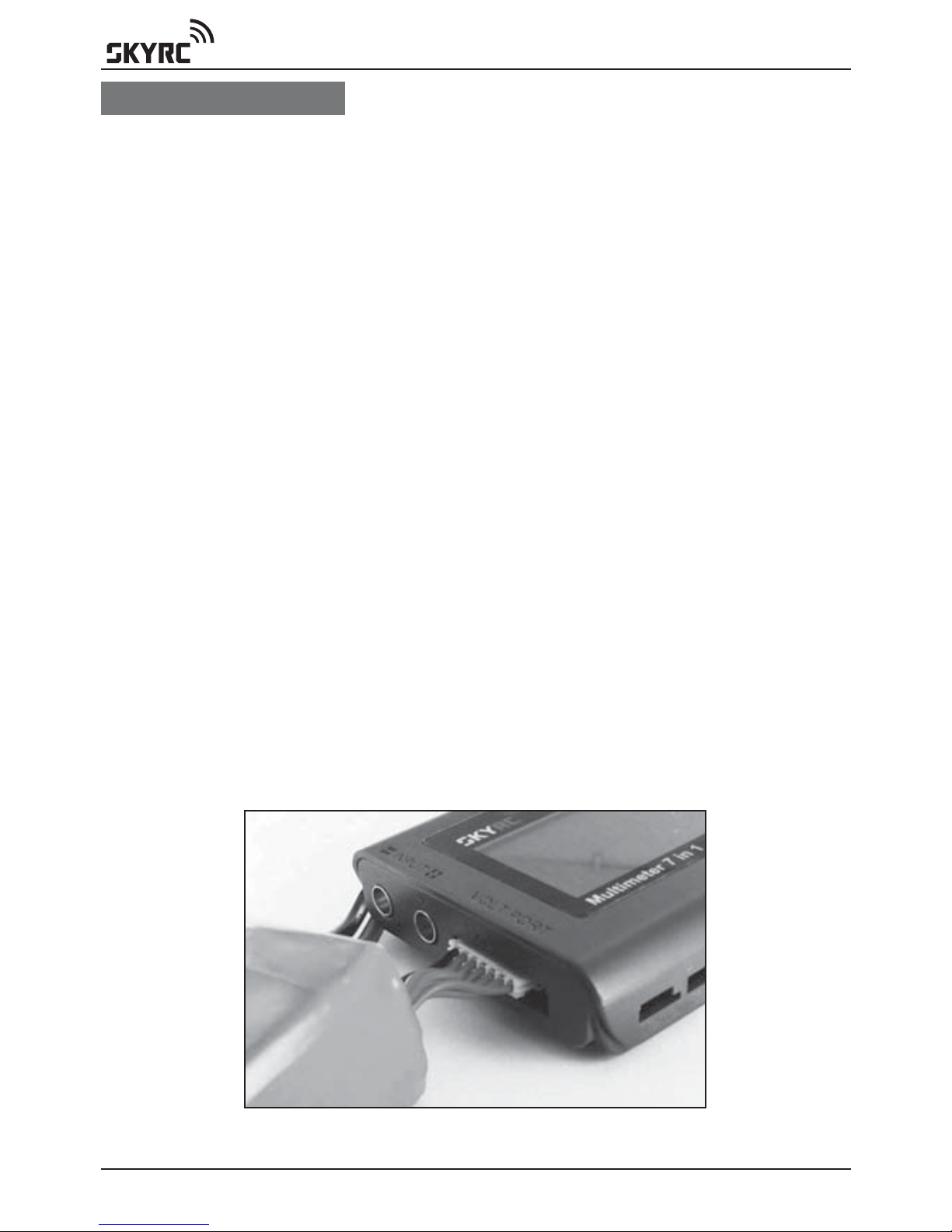
When you connect the balance lead to the i-Meter you must ensure
that both the Ground pin’s for the balance connector and the i-Meter
go together. Different Balance leads have different wiring configurations
and some are colored.
The i-Meter has 2.54mm pin intervals. If the connector on you battery
does not fit do not force the connector, obtain a suitable adaptor lead
from your hobby shop.
Battery Connection Diagram
www.skyrc.com- 07 -
BATTERY CHECKER
Connect the balance lead to ‘VOLT PORT’
Press ‘ENTER’ to enter main function screen
Press ‘ENTER’ to select BATTERY CHECKER function
Press ‘MODE’ to select battery type
Press ‘ENTER’ to confirm battery type
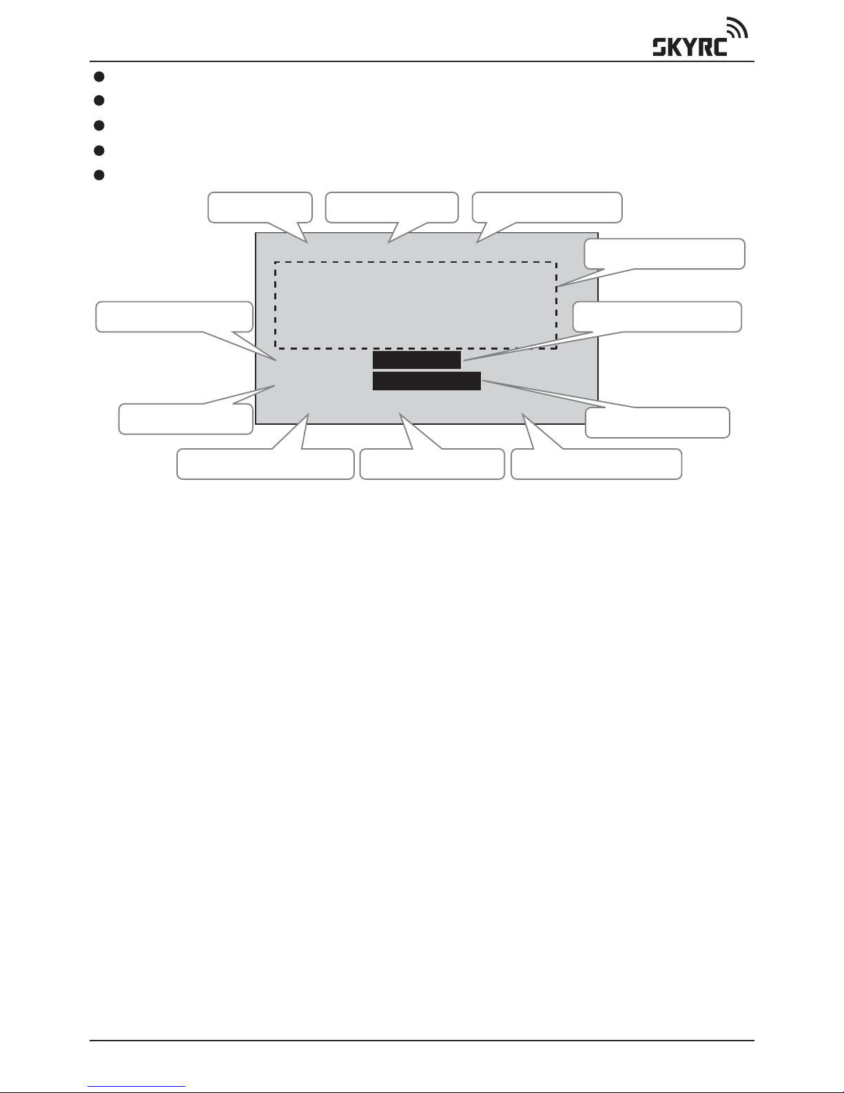
LiPo-6S 23.159V
1)3.847 2)3.847
3)3.852 4)3.859
5)3.877 6)3.878
7)0 8)0
57% E F
69% X 0
3.88-3.85=0.031
Remaining amount fuel gauge
The remaining amount gauge gives you a graphical bar graph display
of the status of the battery by graph and the balance of the cells by
graph. When the battery is fully charged the graph extends to “F” on
the right hand side of the LCD. As in the example you can see that the
battery is about 50% used. There are times when differences occur
between the remaining amount and the actual remaining amount.
These differences can be associated with the quality and use of the
battery and its cells. A battery that has always been charged with a
reputable balancer is likely to reproduce accurate readings on the
i-Meter. A battery that has had a hard life full discharge and recharge
with no balance charging is more likely to have discrepancies between
actual and shown results.
Cell balance gauge
The Cell balance gauge measures the difference between all cells that
are connected to the i-Meter.
Battery Type
The Highest Cell Voltage
Remaining Amount %
Balance Status %
Individual Cell Voltage
Cell Balance Gauge
Lowest Cell Voltage Cell Voltage Differential
Number of Cells Serial Pack Voltage
Remaining Volts Gauge
Serial voltage
Pack voltage of the whole battery (total voltage of all cells) is indicated
The number of serial cells
The total number of cells in the battery pack is indicated (6S as indicated
in the picture 6 serial cells). This is the same as the cell quantity.
www.skyrc.com - 08 -
BATTERY INTERNAL RESISTANCE
The difference is shown graphically between the cell that is showing
the highest cell voltage to the cell that is showing the lowest cell voltage
(largest cell voltage difference) indicated on the graph. When the cell
voltages read equal, the bar extends all the way to the right (O). This
indicates that the cells are all balanced to a satisfactory level. When
the cells have a difference in voltage the bar shortens and indicates
towards the left (X). In order to maintain long lasting battery life if the
balance gauge does not show a satisfactory cell balance then a cell
balancer should be applied to the pack before use. If the cell balance
indication is low after the battery has been used this can be normal and
charging should occur with a balance charger.
BATTERY INTERNAL RESISTANCE
The i-Meter has been created to give you the ability to make an
informed determination of what the true cell and pack ratings by
providing a useful measure, the cell internal resistance.
Int.Resietance
Res:39 mohm
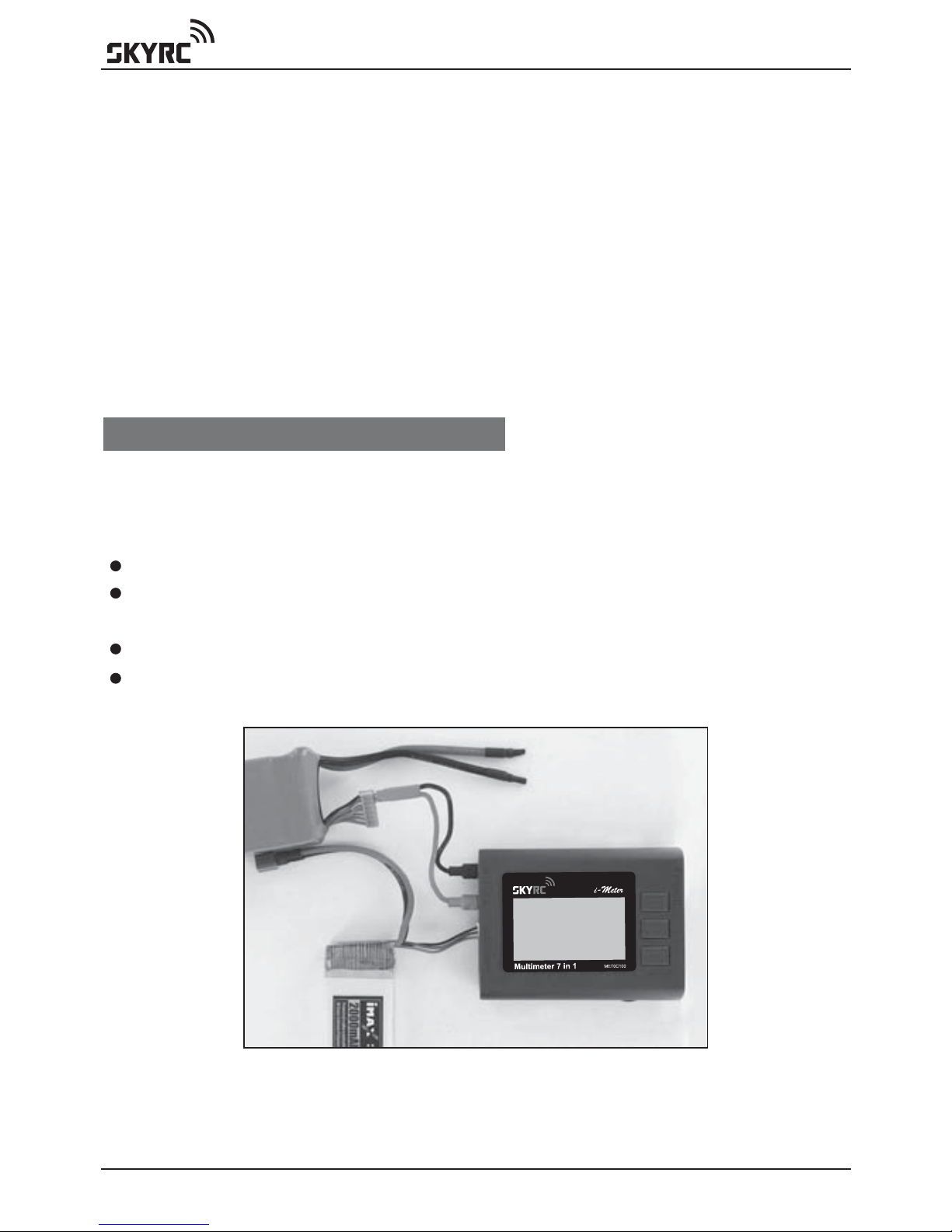
Connection Diagram for Measurement of Battery
Internal Resistance
Connect battery to i-Meter via Voltage Port to power on the i-Meter
Using supplied cable (pitch 2.54mm) to measure individual internal
resistance
Press ‘MODE’ to select ‘INT. RESISTANCE’ function
Press ‘ENTER’ to confirm selection
www.skyrc.com- 09 -
BATTERY INTERNAL RESISTANCE
Cell temperature
For many cell chemistries the resistance of the pack decreases initially
from room temperature to a certain level (perhaps 45C) after which the
resistance of the pack will increase again. Lithium cells in particular
suffer poor cell resistance near 0C.
Cell charge
Generally the closer to a full charge a cell is the lower the internal
resistance.
Cell age
As cells become older their internal resistance tends to increase.
The i-Meter has been built to allow cells to be tested under a known
set of loads which will facilitate comparisons.
Let it be stated that there is no perfect test for cell internal resistance.
Due to the nature of batteries, cells exhibit characteristics of resistance,
capacitance and inductance of which all contribute to the measured
internal resistance. Internal resistance can vary considerably even
within the same cell, this makes the task of determining the internal
resistance a lot harder.
Factors effecting resistance readings:
Contact corrosion
While not actually part of the cell itself, having dirty contacts to the cells
can make a noticeable difference in the resistance. Wiping clean the
contacts can improve contact resistance by 10 or more milliohms.
Once we have an idea of the internal resistance of a cell we can then
use that to determine how efficient our power setup is as well as
knowing how much power is being turned to heat in the battery pack
and additionally know how much the voltage can potentially drop under
load.
BATTERY CHECKER
INT.RESISTANCE
WATT METER
SERVO TESTER
TACHOMETER RPM
TEMPERATURE
THRUST CALC...
SET UP
Int.Resietance
Res: 39 mohm
www.skyrc.com - 10 -
WATT METER
WATT METER
This function measures Current (Amps), Peak current, Voltage (Volts),
Power (Watts), Energy(Watt-Hours) and Charge(Amp-Hours) values for
you, in real-time, for the circuit in which you connect it.
Now you can stop wondering what's going on with your electric model
and get answers that allow you to apply science to your hobby. The
precise measurements you collect will help you fine tune your model
to get all the performance that you paid for.
With watt meter function, it is now easy to determine things like:
Flight time
Current through an ESC and motor
ESC, BEC and motor efficiencies
Charge put into and removed from a battery and the performance of
battery chargers
Battery health
Why power is lost during acrobatics or extreme conditions
i-Meter is activated when the battery is connected to the unit.
Press ‘MODE’ to select ‘WATT METER’ function
Press ‘ENTER’ to confirm selection
PRECAUTIONS
1. Do not leave a cell connected to the i-Meter for more than five
minutes.
2. Be aware that although the i-Meter only takes small samples from
the battery pack, the voltage will be reduced. Make sure you check
your pack balance.
3. Avoid plugging the cell in reverse polarity. The i-Meter can cope with
a reversed connection for a few seconds but it’s still better not to do
it in the first place.
4. Do not connect more than 5V to the cell inputs, again, the IRM can
cope for a few seconds but it’s best not to do it!
Battery
Pack
Speed
Controller
Motor
WATT METER
CURRENT: 35.11A
PEAK(C): 52.11A
VOLTAGE: 25.13V
WATTAGE: 882.31W
PEAK(W): 1309.2W
Energy: 82Wh
Charge: 3.2Ah
Table of contents
Popular Multimeter manuals by other brands


Gossen MetraWatt
Gossen MetraWatt METRAmax 6 operating instructions

PeakTech
PeakTech 4000 Procedure of calibration

YOKOGAWA
YOKOGAWA 90050B user manual

Gossen MetraWatt
Gossen MetraWatt METRALINE DMM16 operating instructions

Fluke
Fluke 8846A Programmer's manual

Tempo Communications
Tempo Communications MM200 instruction manual


