Skyshark Focke-Wulf 190A-8 User manual

Considered a highly risky and unnecessary venture
by urt Tank of Focke-Wulf, the Fw190 eventually
proved to be probably the best fighter produced by
Germany in WWII. Design work was started in 1938
with the idea of using the BMW radial engine
wrapped by the smallest possible airframe. Initial
testing showed that, with the exception of engine
cooling problems, the Fw190 was a superb handling
aircraft, and production variants started rolling off the
assembly line in June 1941. Squadron use quickly
showed that the 190 was more than a match for the
British Spitfires and Hurricanes, and the 190 was well
suited to many other uses, such as dive bombing.
Several variants were introduced in succession, with
the A-8 version being the last of the fighter variants
to be powered by the radial engine. Later versions
switched to an in-line engine, thus the “short nose”
and “long nose” Focke-Wulfs. The A-8 version was
used until the war’s end, side by side with most other
variants, and was a comparable match to the
Mustangs and later Spitfires.
The Fw190 A-8 variant was powered by the BMW
801D-2 radial engine, with a horsepower rating of
1700 hp. Water injection was used to boost takeoff
and combat performance. The Wingspan of the 190
was 34 ft. 5 ½ in, with a length of 29 ft. 5 in. Gross
weight was over 7,600 pounds. Armament varied
greatly, but the standard included two Mg131s in the
fuselage, and four Mg151s in the wing. A variety of
cannons, rocket pods, and bombs could also be car-
ried. Standard crew was one pilot, though there was
room in the aft fuselage to carry another person,
usually a downed pilot picked up during an emer-
gency. A two seat trainer was introduced in the latter
stages of the war.
Skyshark R/C Corporation
75 Mid Cape Terrace, Ste 7
Cape Coral, FL 33991, U.S.A.
Web ite: www. ky harkrc.com
email: c ervice@ ky harkrc.com

Thank you for purchasing the FW 190 from Skyshark R/C
Corporation. For the first time, R/C enthusiasts have a
choice in scale aircraft designs. Our goal, through comput-
er technology and state-of-the-art production techniques, is
to offer aircraft which in the past have not been modeled
simply because they weren’t popular enough to justify mass
production. Our production techniques allow us to produce
aircraft which, though not as popular and well known as P-
51s and P-47s, still offer historical significance (good or
bad!), Good looks and flying characteristics, and a unique-
ness that is sure to turn heads wherever you take your air-
plane!
Your airplane has many unique features
in its design:
CAD Design
CAD design allows strength to be built into the airplane
without sacrificing weight. Accurate parts design and place-
ment ensures a perfect fit.
CAD Drawn Plans
The plans in this kit are not copied from a master set! They
are originals drawn directly from the CAD program where
the airplane was designed. We do this because it allows us
to use color, which helps you better visualize the various
components of the airplane, and we can use better quality
paper, which greatly reduces the possibility of shrinkage.
Since you’re going to build directly on the plans, they ought
to be the proper size! Also, parts placement is guaranteed
to be accurate, so you can build a better, straighter model.
Laser Cut Parts
The same program that generates the design and plans
also drives the laser, so every part is reproduced exactly as
it was designed. Laser cutting also allows us to fit more
parts on each sheet of wood, reducing the waste, and low-
ering the cost to you. Since laser cutting does not have the
same limitations that mechanical cutters do, small and
hard-to-produce parts are simply a computer file away, so
you get a more accurate airplane.
Plastics and Fiberglass
The cowl is accurately reproduced high quality fiberglass.
The canopy is accurately reproduced in clear plastic, and is
molded in two pieces. The wing fillets and other accessories
are molded in plastic to ease the building and finishing
chores!
A Word About the Building Options
Engine Options
Engine choices range from .60 to .68 2-strokes, or .60 to .90
4-strokes. There’s plenty of room in the cowl to mount the
engine in any direction you desire, and you can, with a little
extra thought, completely cowl in the engine; the extra
thought is needed for adequate engine cooling.
Electric Options
Electric conversion on a kit this size is very easy and
straightforward. ou will simply need to plan for a battery
hatch in order to save having to remove the wing for bat-
tery changes. The gun hood on the FW190 makes this very
easy!
Retract Options
Retract installation is shown on the plans and explained in
these instructions for Spring Air or Robart 85 degree
retracts. Of course, you are free to use any retract you wish.
The 85 degree units will not truly reproduce the “canted in”
look of the FW, but will Come very close. Actually, with the
gear canted in scale, the ground handling characteristics
are not as good as if the gear legs are closer to vertical.
Flaps
Flaps on an aircraft this size add more weight and complex-
ity than are offset by any aerodynamic gain, so we elected
to not incorporate flaps into the design of the Focke-Wulf.
Flaps can be added if you wish, but the design and engi-
neering is up to you!
1

General Building Information
The FW190 can be built by a person with average building
skills. It is designed for someone who has built a trainer or
low wing sport plane. No unusual building techniques are
required, although more difficult areas are explained in
detail where necessary. Certain steps in the building
process must be followed as depicted, or you might find
yourself digging back into the structure to redo something.
These areas are outlined when necessary.
Occasionally hints will be included at certain building steps.
These are not required for completion, rather they are tips
intended to ease a particular process.
The laser does not cut through the wood, it burns its way
through. As a result of this, occasionally there will be
scorching on the surface of the wood. This is normal, and is
only a surface discoloration, and does not affect the wood
in any other way. Similarly, the laser settings are optimized
for wood density averages, so occasionally, due to varia-
tions even in individual sheets, some areas might not cut
through completely. This is apparent mainly with the ply-
wood. Simply use care in removing the parts from the
sheets; most of the time, the parts will literally fall out of the
sheets!
The Wing Section building steps are shown for both Fixed
Gear and Retract installation. Decide which gear installation
you want to go with, and use the appropriate building sec-
tion.
Hardware and a motor mount are not included in the kit.
There are so many choices for quality hardware that these
choices are left to the individual preferences of the builder,
rather than include something in the kit that you’ll probably
throw away anyway. A vibration-dampening motor mount is
recommended for use regardless of engine choice, so
select a mount suited to your particular engine.
This aircraft is not a toy. It must be flown in a responsible
manner according to the rules set forth by the Academy of
Model Aeronautics. The builder assumes the responsibility
for the proper assembly and operation of this product.
Skyshark R/C Corporation shall have no liability whatsoev-
er, implied or expressed, arising out of the intentional or
unintentional neglect, misuse, abuse, or abnormal usage of
this product. Skyshark R/C Corporation shall have no liabil-
ity whatsoever arising from the improper or wrongful
assembly of the product nor shall it have any liability due to
the improper or wrongful use of the assembled product.
Skyshark R/C Corporation shall have no liability for any and
all additions, alterations, and modifications of this product.
Having said that mouthful, turn the page and start building
the best airplane on the market!
Accessor es needed to f n sh the FW190:
Sullivan Gold-N-Rods, 48" (Part no. 504) or other appro-
priate pushrods
Sullivan RST-10 or -12 Fuel Tank or other 10 - 12 ounce
fuel tank
Motor mount for appropriate engine
Skyshark FW190A-8 Spinner
3-1/4" Main Wheels (Robart #134)
1-1/2" Tailwheel (Dubro 150TW)
3/16” Gear Straps for gear covers (Dubro #811)
Hinges - We normally use CA hinges for ease.
Control Horns, Clevises, Bolts, Nuts, Screws, etc. (consult
our website)
1/7th Scale Pilot Full or Bust Figure
Engine, Muffler, Radio, Covering, Paint, etc.
Electr c Convers on:
Brushless Outrunner Motor 400-500 v
Skyshark Lightning 75 or E-flite Power 60
ESC: OS70, Cobra 80 or E-flite 80
Battery: Ulti-Power 6-8 cell 5200mAh
Rare Earth Magnets for battery hatch.
Notes:
2

Hor zontal Stab l zer Assembly
1. Slide H1 thru H8 into the slots in H10. Turn this
assembly over (carefully!) And pin to the board. Glue
all the pieces.
2. Glue H9 to the ends of H10.
3. Cut a piece of ¼ x ¼ balsa stock to size and slide it
into the slots in the aft end of the rib jigs to for the
trailing edge. Glue in place.
4. Cut additional ¼ x ¼ balsa pieces to fit between H8
and H9.
5. Slide H11 into the slots in the leading edge and glue.
Slide H12s into place and glue.
6. Carefully remove the tabs on the rib jigs forward of
H11 and H12, and aft of the trailing edge.
7. Use a 1/16” x 4” x 36” balsa sheet to sheet the stab
upper surface.
8. Remove the stab from the board, remove the jigs,
and sand the ribs smooth. Sheet the bottom of the
stab. Trim and sand the sheeting at the trailing edge,
leading edge, and at H9 and the notches.
1. Glue E2s into the slots in E1. Notice that the inside
edge of the stab is angled slightly, while the outside
edge is straight.
2. Fill the inside bay of the elevator with scrap balsa, to
add support for the control arm and elevator joiner
wire. Sand to match the rib contour.
3. Bevel the trailing edge of E1 to match the rib contour.
4. From a 1/16 x 3 x 36 balsa sheet, cut a piece to
serve as the upper sheet. Glue this piece in place,
matching the edge with the ribs.
5. Cut a piece of 3/8 x ¼ balsa stock to size and glue
to the leading edge. Sand the elevator at the leading
edge, trailing edge, and sides.
6. Glue two E3s together, and glue to the outer end of
the elevator. Remember that the elevator has an
inner and outer end!. Sand to match the taper, and
match the forward portion (control horn) to the stabi-
lizer. Repeat for the other elevator.
Elevator Assembly
9. Cut 3/8 x ¼ balsa stock to fit the leading edge, and
glue in place. Sand the leading edges to match the
rib contour and sand to an airfoil shape.
10. Glue two H13s together and glue to the end of the
stab at H9. Sand to shape. Repeat for the other
side.
3

1. Glue R3 thru R7 into the slots in R2.
2. Glue R1 to this assembly, aligning R1 to the top at
R7.
Rudder Assembly
3. Using the same technique as with the elevators,
sheet the remaining side of the rudder. Sand the
leading edges, sides, and trailing edge of the rudder.
4. Glue two R8s together, then center and glue into the
notch between R1 and R3. Add small pieces of 1/16
balsa to the sides of R8 for fill, and sand to match the
rudder taper.
5. Glue two R9s together, and glue to the top of the rud-
der, aligning the trailing edges. Sand to match the
taper, but do not sand the control horn yet. This will
be matched to the vertical when it is built.
A leron Assembly
1. Glue A2 thru A10 into the slots in A1.
2. Fill in the third bay (between A4 and A5) with scrap
balsa for support for the control arm. Sand to match
the rib taper.
3. Cut a piece of ¼ x ¾ balsa stock approximately 2”
longer than the aileron assembly and place the
aileron assembly on this piece. Align the assembly
so that most of the extra length is toward the portion
of the aileron with the rounded end. Also center the
aileron to allow for the additional sheeting to be
added. Glue in place.
4. Cut the opposite side sheeting from 1/16 x 3 x 36
balsa sheet, and glue in place. Sand the trailing
edge, leading edge, and sides.
5. Glue two A11s together, and glue in place to the
aileron assembly. Sand to shape.
Left W ng F xed Gear Assembly
1. Glue W1A to W1, aligning the slot in both pieces.
Glue W1B to W1A. Make a left and right side.
2. Epoxy W3A to W3, aligning the edges. Make a left
and right side. Double-check yourself here - it’s easy
to make two left sides!
3. Epoxy W6A to W6, aligning the edges. Make a left
and right side. Repeat the double-check procedure!
4

4. Glue a ¼ x ¼ balsa spar to W15 Ply spar, aligning
with the bottom edge. For the left side, the balsa spar
will glue to the front of W15.
5. Slide W1 into the center slot in W15. Temporarily
slide the other W1 into the slot as well, but do not
glue. Glue only the left side W1 in place.
6. Align and glue W2, W3, W4, W5, and W6 in place.
7. Glue W7, W8, and W9 in place. Use slight upward
pressure on the balsa spar to fully seat it in the rib
while gluing.
8. Bevel the side of W9A to fit and glue in place.
9. Glue W16 and W17 in place in the notches in the
trailing edges of the ribs.
10. Glue W10 in place.
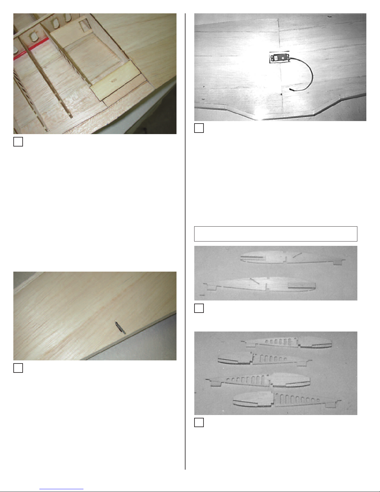
11. If using the single servo aileron setup, do the follow-
ing: Locate and drill the hole for the bellcrank bolt in
W19. Install the bellcrank on W19. Cut the plastic
pushrod housing to 18 1/2” and slide the housing
through the holes in the ribs to W10. Open up the
holes at W10 and W2 slightly to allow for pushrod
movement and glue the housing to all the ribs
except W10 and W2. Install W19 with the bellcrank
side down, and glue W11 in place. Cut two inner
pushrods to 20”, assemble them with the aileron
connector, and slide the pushrod through the hous-
ing. Cut the pushrod at the bellcrank to allow for the
clevis, install the clevis, and connect to the bell-
crank.
12. Glue W12, W13, and W14 in place.
13. Cut a piece of ¼ x ¾ balsa stock to length and glue
to W9 thru W14 as the aileron spar.
5

14. Cut a piece of 3/8 x 1 balsa stock to fit between W1
and W2 for the leading edge. Glue in place. Sand
the leading edge flush with W2.
15. Cut another piece of 3/8 x 1 balsa to fit between the
leading edge at W2 and W4. Sand to fit and glue in
place.
16. Fit the remaining 3/8 x 1 balsa to the leading edge
and glue in place. See Figure 17.
17. Glue the top ¼ x ¼ balsa spar in place.
18. Cut shear webs to fit from W6 to W14 from scrap
3/32” balsa. Sand as needed for a tight fit between
the ribs. Glue between the top and bottm 1/4”
spars as indicated on the plans. The grain in the
shear webs should run vertical.
19. Sand the aileron spar flush with the ribs. Lightly
sand the spar to remove any high spots.
20. Cut two 1/16 x 4 x 36 and two 1/16 x 3 x 36 balsa
sheets to 29”. Edge glue these sheets. Trim the
sheet to match the leading edge.
21. Sheet the top of the wing. Start at the leading edge
and glue except at W1, W2 and W3 - leave this free
until you’ve glued to the spar, then glue.
22. Trim the trailing edge to 0.7 aft of W16 and W17.
Trim and sand the sheeting at W14, W1, and the
aileron.
23. Epoxy the Maple Gear Block to ribs W3, W4, W5,
and W6.
24. Epoxy the Maple Gear Block Anchor to the Gear
Block and W3A. Align so that the Gear Block
Anchor is flush with W3A and perpendicular to the
Gear Block.
25. Add balsa tri-stock to the sides of the Gear Block
Anchor for added support.
26. Carefully drill the Gear Block using a 3/16” bit to
open up the hole for the gear wire. Use caution to
prevent drilling through the top sheeting!
27. Remove the tabs from the bottom of the ribs.
Remove the tab on the bottom aft of W1 and W2
and glue W20 Ply Holddown Plate in place. Trial fit
W18 Servo Tray in place in the slots in W1 and W2,
centering the hole with W1. Do not glue at th s
t me.
28. Sand the aileron spar flush with the ribs. Bevel the
trailing edge sheeting to match the rib contours.
Sand off the tabs on the ply spar, and lightly sand
any high spots on the bottom of the wing.
29. Bend and install the pushrod onto the bellcrank.
Make alignment marks on the aileron spar and the
leading edge for the opening in the bottom sheet-
ing.
6

30. Cut two 1/16 x 4 x 36 and two 1/16 x 3 x 36 balsa
sheets to 29”. Edge glue these sheets. Using the
same techniques as with the top of the wing, sheet
the bottom of the left wing.
31. Trim and sand the sheeting at W1, W14, the trailing
edge, and the aileron opening.
32. Open up the hole in the sheeting for the pushrod,
using the marks made previously as a guide.
33. Glue a ¼ x ¼ balsa spar to W15 Ply spar, aligning
with the bottom edge.
34. Slide W1 into the center slot in W15. Glue to the
other W1. Make a mark on the leading edge for the
dowel opening.
35. Align and glue W2. Slide W18 servo tray in place
and glue. Align and glue W3, W4, W5, and W6 in
place.
R ght W ng F xed Gear Assembly
36. Glue W7, W8, and W9 in place. Use slight upward
pressure on the balsa spar to fully seat it in the rib
while gluing.
37. Bevel the side of W9A to fit and glue in place.
38. Glue W16 and W17 in place in the notches in the
trailing edges of the ribs.
39. Glue W10 in place.
40. If using the single servo aileron setup, do the fol-
lowing: Locate and drill the hole for the bellcrank
bolt in W19. Install the bellcrank on W19. Cut the
plastic pushrod housing to 18 1/2” and slide the
housing through the holes in the ribs to W10. Open
up the holes at W10 and W2 slightly to allow for
pushrod movement and glue the housing to all the
ribs except W10 and W2. Install W19 with the bell-
crank side down, and glue W11 in place. Cut the
pushrod at the bellcrank to allow for the clevis,
install the clevis, and connect to the bellcrank.
7

41. Glue W12, W13, and W14 in place.
42. Cut a piece of ¼ x ¾ balsa stock to length and glue
to W9 thru W14 as the aileron spar.
43. Cut a piece of 3/8 x 1 balsa stock to fit between W1
and W2 for the leading edge. Glue in place. Sand
the leading edge flush with W2.
44. Cut another piece of 3/8 x 1 balsa to fit between the
leading edge at W2 and W4. Sand to fit and glue in
place.
45. Fit the remaining 3/8 x 1 balsa to the leading edge
and glue in place.
46. Glue the top ¼ x ¼ balsa spar in place.
47. Cut shear webs to fit from W6 to W14 from scrap
3/32” balsa. Sand as needed for a tight fit between
the ribs. Glue between the top and bottm 1/4”
spars as indicated on the plans. The grain in the
shear webs should run vertical.
48. Sand the aileron spar flush with the ribs. Lightly
sand the spar to remove any high spots.
49. Cut two 1/16 x 4 x 36 and two 1/16 x 3 x 36 balsa
sheets to 29”. Edge glue these sheets. Trim the
sheet to match the leading edge and the left wing
sheeting.
50. Sheet the top of the wing. Start at the leading edge
and glue except at W1, W2 and W3 - leave this free
until you’ve glued to the spar, then glue.
51. Trim the trailing edge to 0.7 aft of W16 and W17.
Trim and sand the sheeting at W14, W1, and the
52. Epoxy the Maple Gear Block to ribs W3, W4, W5,
and W6.
53. Epoxy the Maple Gear Block Anchor to the Gear
Block and W3A. Align so that the Gear Block
Anchor is flush with W3A and perpendicular to the
Gear Block.
54. Add balsa tri-stock to the sides of the Gear Block
Anchor for added support.
55. Carefully drill the Gear Block using a 5/32” bit to
open up the hole for the gear wire. Use caution to
prevent drilling through the top sheeting!
8
56. Remove the tabs from the bottom of the ribs.
Remove the tab on the bottom aft of W1 and W2
and glue W20 Ply Holddown Plate in place.
57. Sand the aileron spar flush with the ribs. Bevel the
trailing edge sheeting to match the rib contours.
Sand off the tabs on the ply spar, and lightly sand
any high spots on the bottom of the wing.
58. Bend and install the pushrod onto the bellcrank.
Make alignment marks on the aileron spar and the
leading edge for the opening in the bottom sheet-
ing.
59. Cut two 1/16 x 4 x 36 and two 1/16 x 3 x 36 balsa
sheets to 29”. Edge glue these sheets. Using the
same techniques as with the top of the wing, sheet
the bottom of the left wing.
60. Trim and sand the sheeting at W1, W14, the trailing
edge, and the aileron opening.
61. Open up the hole in the sheeting for the pushrod,
using the marks made previously as a guide.
62. Cut the opening in the top sheeting for the servo.
Cut away the excess material at W1 and install the
servo.
63. Trim the sheeting away from the gear wire slots.
64. Using the mark made previously, open up the hole
in the leading edge for the dowel and epoxy the
dowel in place.
65. Glue the wingtips in place. Sand the wingtips to
shape. Sand the leading edge to shape.
Left W ng Retract Assembly
1. Glue W1A to W1, aligning the slot in both pieces.
Glue W1B to W1A. Make a left and right side.
2. Epoxy W5R1 to W5. Epoxy W5R2 to W5R1, aligning
along the upper edge. Make a right and left side.
Double-check yourself here, it’s easy to make two
left sides!!
3. Epoxy W6R1 to W6. Epoxy W6R2 to W6R1, aligning
along the upper edge. Make a right and left side.
Repeat the double-check procedure!
9

4. Glue a ¼ x ¼ balsa spar to W15 Ply spar, aligning
with the bottom edge. For the left side, the balsa spar
will glue to the front of W15.
5. Slide W1 into the center slot in W15. Temporarily
slide the other W1 into the slot as well, but do not
glue. Glue only the left side W1 in place.
6. Align and glue W2, W3, W4, W5, and W6 in place.
Note that W5 and W6 will be installed so that the ply
plates face each other.
7. Glue W7, W8, and W9 in place. Use slight upward
pressure on the balsa spar to fully seat it in the rib
while gluing.
8. Bevel the side of W9A to fit and glue in place.
9. Glue W16 and W17 in place in the notches in the
trailing edges of the ribs.
10. Glue W10 in place.
11. If using the single servo aileron setup, do the follow-
ing: Locate and drill the hole for the bellcrank bolt in
W19. Install the bellcrank on W19. Cut the plastic
pushrod housing to 18 1/2” and slide the housing
through the holes in the ribs to W10. Open up the
holes at W10 and W2 slightly to allow for pushrod
movement and glue the housing to all the ribs
except W10 and W2. Install W19 with the bellcrank
side down, and glue W11 in place. Cut two inner
pushrods to 20”,assemble them with the aileron
connector, and slide the pushrod through the hous-
ing. Cut the pushrod at the bellcrank to allow for the
clevis, install the clevis, and connect to the bell-
crank.
12. Glue W12, W13, and W14 in place.
13. Cut a piece of ¼ x ¾ balsa stock to length and glue
to W9 thru W14 as the aileron spar.
10

14. Cut a piece of 3/8 x 1 balsa stock to fit between W1
and W2 for the leading edge. Glue in place. Sand
the leading edge flush with W2.
15. Cut another piece of 3/8 x 1 balsa to fit between the
leading edge at W2 and W4. Sand to fit and glue in
place.
16. Fit the remaining 3/8 x 1 balsa to the leading edge
and glue in place. See Figure 40.
17. Glue the top ¼ x ¼ balsa spar in place.
18. Cut shear webs to fit from W6 to W14 from scrap
3/32” balsa. Sand as needed for a tight fit between
the ribs. Glue between the top and bottm 1/4”
spars as indicated on the plans. The grain in the
shear webs should run vertical.
19. Sand the aileron spar flush with the ribs. Lightly
sand the spar to remove any high spots.
20. Cut two 1/16 x 4 x 36 and two 1/16 x 3 x 36 balsa
sheets to 29”. Edge glue these sheets. Trim the
sheet to match the leading edge.
21. Sheet the top of the wing. Start at the leading edge
and glue except at W1, W2 and W3 - leave this free
until you’ve glued to the spar, then glue.
22. Trim the trailing edge to 0.7 aft of W16 and W17.
Trim and sand the sheeting at W14, W1, and the
aileron.
23. Epoxy W22 Ply Retract Plate in place in the slots
between W5 and W6.
24. Wheel wells may be added by inserting scrap 1/16”
balsa sheeting using the blue gear door outline as
a guide. Place the wheel wells about 1/8” to 3/16”
inside the outline.
25. Install the retract unit and run the air lines. Install
the retract unit per the instructions with your specif-
ic retract.
26. Install the wheel and strut. Test for fit. Remove the
retract and wheel.
27. Remove the tabs from the bottom of the ribs.
Remove the tab on the bottom aft of W1 and W2
and glue W20 Ply Holddown Plate in place. Glue
W18 Servo Tray in place in the slots in W1 and W2,
centering the hole with W1.
28. Sand the aileron spar flush with the ribs. Bevel the
trailing edge sheeting to match the rib contours.
Sand off the tabs on the ply spar, and lightly sand
any high spots on the bottom of the wing.
29. Bend and install the pushrod onto the bellcrank.
Make alignment marks on the aileron spar and the
leading edge for the opening in the bottom sheet-
ing.
11

30. Cut two 1/16 x 4 x 36 and two 1/16 x 3 x 36 balsa
sheets to 29”. Edge glue these sheets. Using the
same techniques as with the top of the wing, sheet
the bottom of the left wing.
31. Trim and sand the sheeting at W1, W14, the trailing
edge, and the aileron opening.
32. Open up the hole in the sheeting for the pushrod,
using the marks made previously as a guide.cut out
the opening for the retract and wheel.
33. Glue a ¼ x ¼ balsa spar to W15 Ply spar, aligning
with the bottom edge.
34. Slide W1 into the center slot in W15. Glue to the
other W1. Make a mark on the leading edge for the
dowel opening.
35. Align and glue W2, W3, W4, W5, and W6 in place.
Note that the ply plates on W5 and W6 face each
other.
R ght W ng Retract Assembly
36. Glue W7, W8, and W9 in place. Use slight upward
pressure on the balsa spar to fully seat it in the rib
while gluing.
37. Bevel the side of W9A to fit and glue in place.
38. Glue W16 and W17 in place in the notches in the
trailing edges of the ribs.
39. Glue W10 in place.
40. If using the single servo aileron setup, do the fol-
lowing: Locate and drill the hole for the bellcrank
bolt in W19. Install the bellcrank on W19. Cut the
plastic pushrod housing to 18 1/2” and slide the
housing through the holes in the ribs to W10. Open
up the holes at W10 and W2 slightly to allow for
pushrod movement and glue the housing to all the
ribs except W10 and W2. Install W19 with the bell-
crank side down, and glue W11 in place. Cut the
pushrod at the bellcrank to allow for the clevis,
install the clevis, and connect to the bellcrank.
12

41. Glue W12, W13, and W14 in place.
42. Cut a piece of ¼ x ¾ balsa stock to length and glue
to W9 thru W14 as the aileron spar.
43. Cut a piece of 3/8 x 1 balsa stock to fit between W1
and W2 for the leading edge. Glue in place. Sand
the leading edge flush with W2.
44. Cut another piece of 3/8 x 1 balsa to fit between the
leading edge at W2 and W4. Sand to fit and glue in
place.
45. Fit the remaining 3/8 x 1 balsa to the leading edge
and glue in place.
46. Glue the top ¼ x ¼ balsa spar in place.
47. Cut shear webs to fit from W6 to W14 from scrap
3/32” balsa. Sand as needed for a tight fit between the
ribs. Glue between the top and bottm 1/4” spars as
indicated on the plans. The grain in the shear webs
should run vertical.
48. Sand the aileron spar flush with the ribs. Lightly
sand the spar to remove any high spots.
49. Cut two 1/16 x 4 x 36 and two 1/16 x 3 x 36 balsa
sheets to 29”. Edge glue these sheets. Trim the
sheet to match the leading edge and the left wing
sheeting.
50. Sheet the top of the wing. Start at the leading edge
and glue except at W1, W2 and W3 - leave this free
until you’ve glued to the spar, then glue.
51. Trim the trailing edge to 0.7 aft of W16 and W17.
Trim and sand the sheeting at W14, W1, and the
aileron.
52. Epoxy W22 Ply Retract Plate in place in the slots
between W5 and W6.
53. Wheel wells may be added by inserting scrap 1/16”
balsa sheeting using the blue gear door outline as
a guide. Place the wheel wells about 1/8” to 3/16”
inside the outline.
54. Install the retract unit and run the air lines. Install
the retract unit per the instructions with your specif-
ic retract.
55. Install the wheel and strut. Test for fit. Remove the
retract and wheel.
13

56. Remove the tabs from the bottom of the ribs.
Remove the tab on the bottom aft of W1 and W2
and glue W20 Ply Holddown Plate in place.
57. Sand the aileron spar flush with the ribs. Bevel the
trailing edge sheeting to match the rib contours.
Sand off the tabs on the ply spar, and lightly sand
any high spots on the bottom of the wing.
58. Bend and install the pushrod onto the bellcrank.
Make alignment marks on the aileron spar and the
leading edge for the opening in the bottom sheet-
ing.
59. Cut two 1/16 x 4 x 36 and two 1/16 x 3 x 36 balsa
sheets to 29”. Edge glue these sheets. Using the
same techniques as with the top of the wing, sheet
the bottom of the left wing.
60. Trim and sand the sheeting at W1, W14, the trailing
edge, and the aileron opening.
61. Open up the hole in the sheeting for the pushrod,
using the marks made previously as a guide. Cut
out the opening for the retract and wheel.
62. Cut the opening in the top sheeting for the servo.
Cut away the excess material at W1 and install the
servo.
63. Trim the sheeting away from the gear wire slots.
64. Using the mark made previously, open up the hole
in the leading edge for the dowel and epoxy the
dowel in place.
65. Glue the wingtips in place. Sand the wingtips to
shape. Sand the leading edge to shape.
Fuselage Assembly
1. Make two ¼ x ¼ balsa crutches by splicing pieces of
36” balsa stock to length.
2. Pin the ¼ x ¼ crutches in place on the plans.
3. Glue F1A, F2A, and F3C in place, aligning with the
bulkhead layout on the plans. Note that F1A is offset
to allow for engine right thrust.
4. Glue F4A thru F12A in place.
5. Glue F13 and F14A in place.
14
See the Coc pit installation instructions at the end of
this manual now for instructions on installing the
optional coc pit that is included with this it. If you do
not wish to install the coc pit, continue with the stan-
dard instructions.

6. Glue F16 cockpit floor in place.
7. Glue F18 in place.
8. Glue F19 in place. Remove the openings for the
cockpit, match the ends of F18 and F19 together and
glue.
9. Glue pieces of ¼ x ¼ balsa stock into the slots in the
bulkheads, starting at F10A. This piece will extend to
F19, and will need to be beveled where it meets F19.
10. A short section of ¼ x ¼ will run between F3C and
F1A. Glue in place.
11. Add 1/8 x ¼ stringers to the fuselage assembly. Add
the bottom stringer first - it runs from F14A to F1A.
12. A short stringer section will then run from F14A thru
F12A and butt against F11A.
13. The second stringer will run from F12A to F1A.
14. The third stringer will run from F12A, and butt
against F8A. The other section will run from F3C to
F1A.
15. Glue F20 Stab Saddle in place between F12A and
F14A. Bevel the ends of F20 as necessary to fit at
F14A.
16. Sheet the upper fuselage using 1/16” x 4” x 36” balsa
sheets Edge glue the sheets as necessary. Pin small
pieces of 1/8 x ¼ scrap against the sides of the crutch.
This will raise the sheeting up 1/8”, so the lower sheeting
will attach to the crutch when it is added. A small piece will
need to be edge glued to the upper portion of the sheet
between F7A and F10A. Add this section, and use the fol-
lowing as a guide: The best way to assure a straight fuse
(that I’ve found) is to match the left and right sheets for
density, then start the sheeting on both sides of the fuse
at the same time. Slowly work the sheet up the fuselage
sides, one stringer section at a time, starting in the mid-
dle and working alternately to both ends. Do one stringer
row, then move to the opposite side and do that stringer
row, and so forth. When you have difficulty making the
sheet conform to the fuse sides, wet the sheet with an
ammonia solution (Windex with Ammonia in the spray
bottle works great and doesn’t stain the wood!) And con-
tinue. As you get close to the top, pick one side and sheet
to the ¼ x ¼ keel. Then work the other side to the same
point.
15

17. Add sheeting to the upper forward fuse to complete
that section. Trim and sand the sheeting at F3C to
F19. Try to achieve a level surface across F19 - you
may have 1/32” to 1/16” of sheeting not flush at the
rear of F19 - this is O .
18. Trim the sheeting to within ¼” of F1A. Leave the
extra hanging in front to allow for the F15 Firewall.
19. Trim and sand the sheeting between F10A and
F12A, down to the stringer.
20. Trim and sand the sheeting even with F20.
21. Remove the upper fuse from the board. Glue F1B,
F2B, F3B, F4B, F5B, and F6B in place.
22. Epoxy F15 Firewall to F1A and F1B.
23. Glue F21 Ply Wing Saddle in place. The forward
portion has to make a radical curve, so the best
way to achieve this is to break the outer plies where
F21 meets F2B to make it conform. This area is not
a structural load bearer, so it’s O to do this.
24. Epoxy F22 Ply Holddown Plate in place in the slots
in F21.
25. Cut and glue the rudder and elevator pushrod
housings in place. Cut the openings in the aft fuse
between F12 and F13 for pushrod exits.
26. Glue F7B thru F12B in place.
27. Cut a ¼ x ¼ balsa keel to fit and glue in place.
28. Add 1/8 x ¼ balsa stringers to F1B and F2B, and to
the aft lower fuselage between F6B and F12B. .
29. Add an additional short stringer between F6B and
F7B, right at the sharp corner.
30. Sheet the lower fuselage. As you work up the fuse
sides, cut the sheeting lengthwise between F6B
and F7B. When making the corner, this area will
lay flat. Wet the sheeting while working around the
corner, and continue sheeting to F12B.
16

31. Continue the sheeting forward, but leave an open-
ing as shown. You will need access to this area
when mounting the wing.
32. Trim and sand the sheeting at F15, F12B, and the
wing saddle.
33. Lay the wing in the saddle and align. Trim the sad-
dle as necessary for a good fit.
34. With the wing aligned, slide F23 over the wing
dowel and epoxy to F2B.
35. Sheet the remainder of the forward fuselage.
36. Align the wing and drill and install the wing hold-
down bolts.
37. With the wing in place, fit and glue F2C to the lead-
ing edge of the wing.
38. Glue two W21s together. Fit and glue to F2C and
the bottom of the wing. Trim and sand to match the
fuselage.
1. Glue S1 and S2 together.
2. Trail fit this assembly to the tail section - trim as nec-
essary.
3. With the S1/S2 assembly flat, glue the S3 spar, and
S4, S5, and S6 ribs.
4. Align and glue S3 thru S6 to the opposite side of the
vertical.
5. Glue S6 to the top of S1/S2.
Vert cal Stab l zer Assembly
17

6. Glue short pieces of tri-stock to the inside of F20 for
added horizontal stabilizer support.
7. Align and glue the horizontal stabilizer in place.
8. Align and glue the vertical stab assembly to F12, F14
and the horizontal stab.
9. Cut the vertical stab leading edge from ¼ x ¼ balsa
and glue in place.
10. Fit the upper fuselage block in place, trim and glue.
Sand to a rough shape to conform to the fuselage
and F12A.
11. Glue F24 to the vertical and horizontal. The front
edge will wrap up F12A.
12. Cut and edge glue sheeting for the stab. The lower
aft edge will follow F24, but the lower forward edge
will have to be trimmed to fit along F24, F12, and
the leading edge. Sheet the vertical stab.
13. Glue two S8s together and glue to the top of the
vertical stabilizer. Sand to shape.
14. The area shown by the arrow should be filled with
lightweight filler and sanded to shape. Sand the
fuse block and tail area to shape.
Fuselage F nal Assembly
1. Cut the gun hood out and fit to the upper fuselage.
Cut the cockpit glare shield to fit as shown on the
plans and in the photo.
2. Cut the instrument panel from the 3-view drawing
and glue to the back of the laser-cut instrument
panel. Glue the instrument panel in place.
3. Epoxy the gun hood in place. Fill and sand the joint
along the fuse as necessary.
4. Glue F27 Headrest in place.
5. Trim and fit the canopy in place. Finish the cockpit as
desired, and glue the canopy in place.
6. Trim and fit the aft canopy shell. Glue to the canopy
and the fuselage.
18

7. With the wing in place, glue F24 balsa fillets in place
to the lower fuse, aligning with the trailing edge of
the wing. Do not glue F24 to the wing.
8. Cut and trim the plastic wing fillets to shape, and
glue in place.
9. Trim and fit the cowl to the fuse. As an added
strengthener, glue small (1”) squares of sheet alu-
minum or carbon fiber to the inside of the cowl at the
screw holes, then add the fiberglass over these. This
will prevent the screw holes from cracking.
The remainder of the construction consists of attaching
the rest of the components to the airplane. Most of this is
builder’s choice, and individual tastes, styles, and compo-
nent selection, so any detailed descriptions would be
impossible. The remainder of assembly is described in
general terms only.
Engine Installation:
The engine centerline is marked on F15. Locate and drill
the holes for your motor mount. Install the motor mount
and engine of your choice.
Fuel Tan and Throttle Cable:
After deciding which direction the engine will point (up,
down, or sideways) drill holes for and install the throttle
cable. Mount the fuel tank of your choice, and connect the
lines.
Servo and receiver installation:
3/8” maple blocks are provided for servo rails.. Mount
these as shown on the plans and mount the servos.
Mount the receiver and connect the components. The bat-
tery pack may be located anywhere in the fuselage for
balance purposes.
Covering:
Cover the airplane with the covering of your choice. The
covering choices are too numerous to mention, but the
airplane shown on the box was covered with film, painted,
and clear-coated. It is recommended that the airplane and
control surfaces be covered separately.
Control surfaces:
Locate the control horn positions. Final sand the control
surfaces. Locate the hinge points (hinges and other hard-
ware are not provided in the kit because everyone has his
own preferences. Rather than put in stuff that most of you
will throw away, we left it out to keep the kit price down)
and install the hinges and control surfaces. Use at least
three hinges per control surface for best results. Connect
and adjust the pushrods.
Landing Gear (Fixed):
Insert the main gear wire legs into the slots in the wings,
secure with straps, and mount the wheels of your choice.
Landing gear (Retracts): Bend the gear wire to match the
angle shown on the plans, and install the gear legs and
wheels. Install the remainder of the retract components
per the retract instructions.
Center of Gravity:
The CG is measured with the aircraft UPSIDE DOWN 4-
13/16” back for the wing leading edge, where the wing
meets the fuselage.
Control Throws:
Ailerons: 7/16” up & down
Elevator: 1/2” up & 3/8”down
Rudder: 1” left & right
The rest is up to you! Fly and enjoy!
F nal Assembly
19
This manual suits for next models
1
Table of contents
Other Skyshark Toy manuals


