Skytron HA30AR-WC User manual

HA30AR-WC & HA60AR-WC
MINI-ARGOS
REMOTE CONTROLLED SURGICAL LIGHT
OPERATORS, MAINTENANCE AND PARTS
REV 2/08


Page 1
TABLE OF CONTENTS
Title Page
Although current at the time of publication, SKYTRON'S policy of continuous development makes this
manual subject to change without notice.
EQUIPMENT LABELS AND SPECIFICATIONS .................................................................................... 2
SPECIAL USER ATTENTION ................................................................................................................ 3
INTRODUCTION..................................................................................................................................... 4
SECTION I - OPERATION...................................................................................................................... 5
Wall Intensity/Positioning Control ................................................................................................. 5
PositioningWand.......................................................................................................................... 5
Positioning Wand Operation......................................................................................................... 5
SECTION II - MAINTENANCE................................................................................................................ 6
Positioning Wand Batteries .......................................................................................................... 6
Positioning Wand Strobe Bulb...................................................................................................... 6
Halogen Bulb Replacement.......................................................................................................... 6
Bulb Voltage Adjustment .............................................................................................................. 7
Cleaning ....................................................................................................................................... 7
Testing.......................................................................................................................................... 8
Service ......................................................................................................................................... 8
Wiring Diagrams........................................................................................................................... 9
SECTION III - REPLACEMENT PARTS............................................................................................... 10
3-1 Light Fixture and Control Box Assembly ............................................................................ 10
3-2 HA30AR-WC Positioning Wand ......................................................................................... 12
3-3 HA60AR-WC Positioning Wand ......................................................................................... 14
3-4 HA60AR-WC Charging Unit ............................................................................................... 16
3-5 Wall Positioning Control ...................................................................................................... 18
Fixture Wiring ............................................................................................................................. 20
Page 2
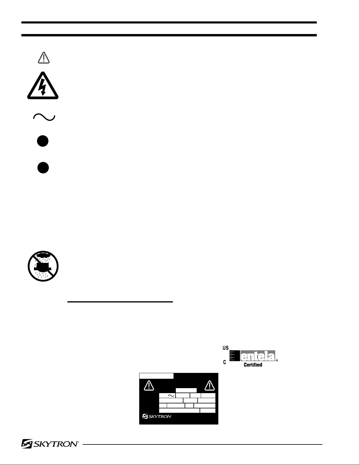
F2 FUSE TYPE 1/4 AMP, SLOW BLOW TYPE
FOR DRY LOCATIONS
UNIT TO BE USED ONLY IN SPECIFIED ENVIRONMENTAL CONDITIONS
TEMPERATURE: 15 - 30 C (60 -85 F)
ATTENTION, CONSULT MANUAL FOR FURTHER INSTRUCTIONS.
INDICATES SPECIAL USER ATTENTION.
AC VOLTAGE, CONTINUOUS OPERATION
HUMIDITY: 30% - 60% RELATIVE HUMIDITY, NON CONDENSING
EQUIPMENT LABELS AND SPECIFICATIONS
.25
F1 FUSE TYPE 1 AMP, SLOW BLOW TYPE
1A
INDICATES DANGEROUS VOLTAGE, 120 V, 60 Hz
V
VOLTAGE RATING OF THE UNIT
A
AMPERAGE RATING OF THE UNIT
HZ
FREQUENCY OF THE UNIT
ENTELA CERTIFIED
TO UL2601-1
CAN/CSA601.1, IEC 60601-2-46
SERIAL NUMBER LABEL
ELECTRICAL SPECIFICATIONS
POWER REQUIREMENTS -- 120VAC, 60HZ 100W, SINGLE PHASE
CURRENT LEAKAGE -- LESS THAN 100 MICRO AMPS
INPUT VOLTAGE TO FIXTURE NOT TO EXCEDE 3% NOMINAL VOLTAGE
FUSE SLOW BLOW
GRAND RAPIDS, MI
1-800-SKYTRON • (616) 957-0500
DAIICHI SHOMEI CO., LTD.
MADE IN JAPAN
REFERTO ACCOMPANYING DOCUMENTS
1A
ELECTRIC RATING
CAT. NO.
BULBSTYPE
SERIAL NO.
24V 100W
INPUT 120V
H24100 1.25A 100W 60Hz
HA60AR-WC

Page 3
SPECIAL USER ATTENTION
To help assure the highest degree of operating
safety for user and patient, SKYTRON has pro-
vided precautionary instructions throughout this
manual.
As with the operation of any surgical light, all
hospital personnel should be aware that a certain
amount of care must be exercised to maintain
patient safety and to keep your SKYTRON light
fixture performing at peak efficiency.
The following is a summary of the important pre-
cautionary instructions:
•Make sure the electrical power to the fix-
ture is "OFF" and the bulb is cool. Using
caution not to touch the reflector surface,
hold the bulb by the base and pull out.
•To prolong bulb life, the Sof-Start bulb
protection circuit will cause a slight delay
beforethebulbwill illuminate.
•Halogen bulbs are sensitive to body oils.
DO NOT handle glass surface of bulb as
bodyoilfromfingerscancreatea"hotspot"
andmaycausethebulbtoburnoutprema-
turely.
•Voltage adjuster is located on the back of
the intensity control. Wall control must be
removed from switch box to make the ad-
justment by an authorized service person.
•Equipmentnotsuitableforuseinthepres-
ence of flamable anaesthetic mixture with
air or with nitrous oxide.
•Where applicable - remove batteries if
equipmentisnotgoingtobeusedforsome
time.
•Warning - risk of fire, replace with 24V
100W Tungsten Halogen Lamp.
•Warning-forcontinuedprotectionagainst
riskoffire,replaceonlywithsametypeand
rating of fuse.
•Caution - before operation remove top
cover, discard packing material and verify
that all circuit boards are in place.
•Notice - Thermaly protected fixture. Blink-
inglightmayindicateinsulationtoocloseto
fixture or fixture installed where spacings
are less than those specified.
•It is recomended to keep the equipment
away from disturbance sources including
electromagnetic fields in order to avoid
malfunctioningoftheequipment.
•A dedicated circuit & circuit breaker is
required for fixture.

Page 4
WALL CONTROL
INTRODUCTION
The Mini-Argos Surgical Lighting System from
SKYTRON consists of a lighthead with optical
sensors and computer circuitry for lighthead posi-
tioning. The lighthead is positioned by means of a
hand-held,wirelessremotecontrolunit(positioning
wand). Whenactivated,thepositioningwandemits
a bright high frequency strobe light. Photoelectric
elements located in the lighthead sense the signal
emittedbythewandandcreateinputsignalstothe
internalcomputercircuitry. The computercircuitry
simultaneously activates the two positioning mo-
tors until the light beam is focused directly on the
positioningwand.
TheON-OFFswitchandlightintensitycontrolsare
located on the wall control. The wall control also
offers positioning back-up.
POSITIONING WAND
HA30AR-WC POSITIONING WAND AND
CHARGING UNIT
HA60AR-WC

Page 5
SECTION l - OPERATION
Figure 1-1. Wall Control
Whenlightisno longerneeded,lowerthe intensity
control and turn power "OFF" with main power
switch.
POSTIONING WAND
Thepositioningwandisthehand-heldremotecon-
trol device that activates the lighthead positioning
function. See Figure 1-2.
Before use in a surgical area, cover the wand with
a sterile drape.
WALL INTENSITY/POSITIONING CONTROL
The wall mounted control "ON-OFF" switch sup-
plies direct power to the Mini-Argos positioning
circuit. Theintensitycontrolknobregulatesinputto
the bulb circuit. See Figure 1-1. Turn power "ON"
with the main power switch. Adjust the light inten-
sity with the intensity control knob.
NOTE
To prolong bulb life, the Sof-Start bulb
protection circuit will cause a slight de-
lay before the bulb will illuminate.
POSITIONING WAND OPERATION
To initially position the lighthead, turn the main
power switch "ON" and hold the strobe end of the
positioningwand inthe light beam path. Press the
momentary switch button on the side of the wand.
Whenthelightheadbeginstomove,holdtheswitch
buttondown,movethewandtothedesiredposition
and release the switch. With the positioning wand
in its sterile drape, the light can be repositioned
precisely as desired during surgery. Hold the
strobe end of the control wand in the light path,
presstheswitchbutton,movethewandto the new
position and release the switch.
A Battery Indicator Light, located on the wand, will
go "ON" when button is pushed. When the button
ispushedandtheredlightgetsdimmerorgoesout,
the batteries need to be changed.
HA30AR-WC POSITIONING WAND
The positioning wand is powered by two C-size
alkalinebatteries. Erraticmovementofthelighthead
or failure of the lighthead to follow the wand cor-
rectly are symptoms of low battery voltage. To
replacethe batteries, use the following procedure:
1. Slide the battery cover toward the end of the
main case and remove it. See Figure 2-1.
2. Remove old batteries.
3. Install two new C-size alkaline batteries.
Batterypositioning(polarity) isengravedin control
wand case.
Figure 1-2. Positioning Wand Figure 2-1. HA30AR-WC Positioning Wand
POSITIONIN
G
BUTTONS
INTENSITY
C
ONTROL KNOB
MAIN
POWER SWITCH LIGHT
SELECT SWITCH
BATTER
Y
INDICATO
R
LIGHT
SWITCH
S
TROBE
BULB
BULB
C
ONTACT
ALKALINE
BATTERIES
BATTER
Y
COVE
R
BULB
BULB
COVER

Page 6 SECTION II - MAINTENANCE
4. Inspect the battery contact on the end cover
for corrosion, looseness, or bent contact.
5. Line up sides of the battery cover with slots
in main case and replace end cover.
HA60AR-WC POSITIONING WAND
The HA60AR-WC positioning wand is powered by
rechargeable batteries. Erratic movement of the
lighthead or failure of the lighthead to follow the
wand correctly are syptoms of low battery charge.
The probe also has a low battery voltage indicator
light that will illuminate or blink when the batteries
need to be charged.
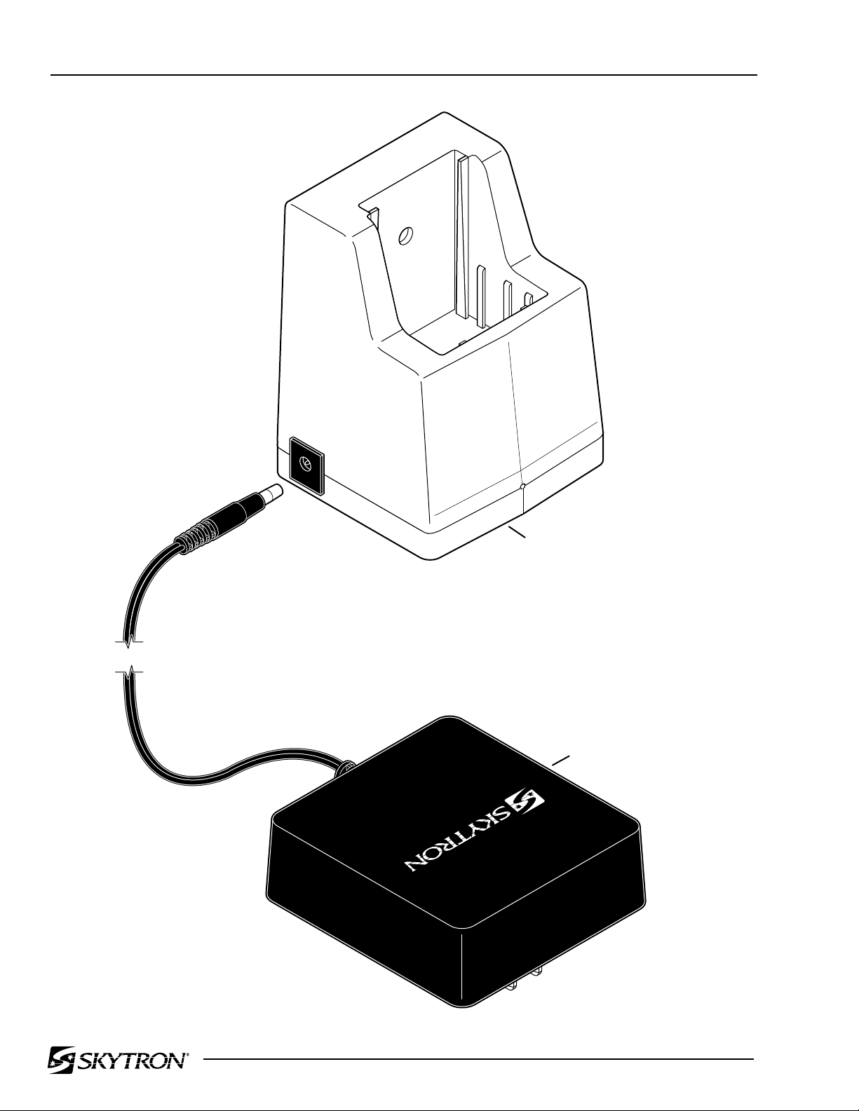
To recharge the batteries, insert the wand into the
recharging base as shown in Figure 2-2. A com-
plete charge will take approximately 4-5 hours.
3. Align the three prongs on the new bulb with
theircorrespondingcontactholesinthewand(pins
are arranged so bulb will fit properly in only one
position) and push new bulb into place.
4. Replace bulb cover.
HALOGEN BULB REPLACEMENT
To replace the halogen bulb, use the following
procedure:
1. Loosenthethumbscrewsecuringthediffuser
cover and lower the cover. See Figure 2-3.
POSITIONING WAND STROBE BULB
Toreplace thestrobe bulb refer to figure2-1 or2-2
and use the following procedure:
1. Unscrew and remove the bulb cover.
2. Holdthebulbbythebaseandpullstraightout.
Figure 2-2 HA60AR-WC Positioning Wand
Figure 2-3.
2. Using caution not to move the photoelectric
eyes, remove the two thumbscrews securing the
filter assembly and remove the filter assembly.
3. Make sure the electrical power to the fixture
is "OFF" and the bulb is cool. Using caution not to
touch the reflector surface, hold the bulb by the
baseandpullout. SeeFigure2-4. Slightlyworking
the bulb back and forth may aid in removal.
NOTE
TheHalogenbulbsaresensitivetobody
oils. DO NOT handle glass surface of
new bulb as body oil from fingers can
create a "hot spot" and may cause the
bulb to burn out prematurely.
BULB COVER BULB
P
OSITIONING
WAND
RECHARGIN
G
BASE
BULB CONTAC
T
THUMBSCREW FILTER
THUMBSCREW
FILTER
ASSEMBLY
PHOTOELECTRIC EYES

Page 7
BACK VIEW OF
WALL CONTROL
VOLTAGE
ADJUSTER
WIRES
METER
TEST LEADS
BULB
Figure 2-5.
4. Adjust the voltage to the bulb by turning the
adjuster on the back side of the intensity control.
See figure 2-6.
Figure 2-4.
4. Holding the bulb by the base, plug it directly
into the socket. DO NOT touch the glass portion
ofthebulborthereflectorsurfacewithyourfingers.
This can best be done by using a clean cloth
around the base of the bulb when installing. Be
surebulbbase isproperlyseated inthe connector
to insure proper focus alignment.
BULB VOLTAGE ADJUSTMENT
To insure maximum intensity and to prolong bulb
life,thevoltagetothebulbshouldbe20VAC. Use
thefollowing procedure to test andadjust the bulb
appliedvoltage.
1. Bulb voltage must be tested with the bulb
illuminated. Duetolimitedspaceatthebaseofthe
bulbformetertestleads,2 small wiresattachedto
the bulb prongs will simplify the test.
2. Remove the diffuser and remove the bulb.
Attach 2 small wires to the prongs of the bulb and
reinstallthebulb. Connectthe2wirestothemeter
test leads.
3. Turn main power "ON" and set the Dimmer
Control to maximum intensity for the test. Output
voltage (at the bulb) should be 20V. See figure 2-5.
NOTE
Voltageadjusterislocatedontheback
of the intensity control. Wall control
must be removed from switch box to
make the adjustment.
Figure 2-6.
5. Turn the adjuster clockwise to increase the
output voltage, counterclockwise to decrease the
voltage. Proper voltage should be 20V.
CLEANING
Lighthead exterior - Should be wiped down periodi-
cally or between cases with a mild cleaning agent
which will not adversely affect the painted or plastic
surfaces.
Lighthead interior - Should be cleaned once a year
or as applicable.
Filter - Should be removed periodically to remove
dust and lint. Dust off with a dry cloth or wash and
air dry as desired.
Thediffusershouldbecleanedusinga"plexiglass"
cleaner such as "210 Plus Cleaner and Scratch
Remover" available from Summer Labs (1-800-
542-8656, Fax 617-482-9001) or equivalent. DO
NOT use alcohol based cleaners on the diffuser.
Duringscheduledcleaningofthelightheadinterior,
all moving parts should be lubricated.
REFLECTOR
SURFACE
END
CAP
BASE

Page 8
LIGHTHEAD JUNCTION BOX
WIRE COLORS VOLTAGE
HIGH VOLTAGE
Red & White = 120 VAC
LOW VOLTAGE
Yellow & Brown = +15 VDC
Yellow & Black = -15 VDC
Yellow & Orange = +15 VDC with Foot Button Actuated
= -15 VDC with Head Button Actuated
Yellow & Blue = +15 VDC with Left Button Actuated
= -15 VDC with Right Button Actuated
Lighthead Housing Connector
PIN # WIRE COLOR
1 Green
2 White
3 Red
4 Brown
5 Yellow (mobility circuit common)
6 Black
7 Not Used
8 Not Used
9 Orange
10 Blue
Or contact:
SKYTRON
5085 Corporate Exchange Blvd. S.E.
Grand Rapids, MI 49512
1-800-SKYTRON (1-800-759-8766)
Fax. 1-616-656-2906
SERVICE
TheMini-ArgosLightheadhasmanysensitivecom-
ponents that should not be worked on or adjusted
by untrained maintenance personnel. Preventive
maintenance performed by SKYTRON factory
trained service representatives, using authorized
parts and service techniques, will assure the ex-
tendedandreliableperformanceofyourMini-Argos
Surgical Lights.
For factory service or preventive maintenance
contracts on SKYTRON Mini-Argos lighting sys-
tems, contact your SKYTRON representative:
TESTING
Ifthelightfixturedoesnotfunctionproperly,testthe
lighthead wiring at the wire connections in the
lighthead junction box for proper voltages.

Page 9
CONTROL BOX
LIGHTHEAD
F1
F2
REFER TO PAGES 20,21,22 FOR FIXTURE WIRING CONNECTIONS
Page 10 SECTION III - REPLACEMENT PARTS
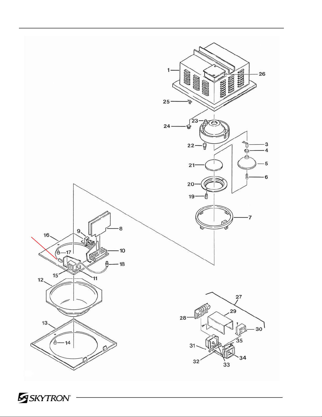
3-1. LIGHT FIXTURE AND CONTROL BOX ASSEMBLY
B5-011-37-1
BLOCK
(2-08)

Page 11
Item Part No. Description Qty.
1 B5-011-30-C ENCLOSURE, white ........................................................................................................ 1
2 B5-011-31-1 HOLDER, bulb and reflector ............................................................................................ 1
3 B1-010-61 SOCKET, Halogen bulb................................................................................................... 1
4 B1-010-62 CLAMP, Halogen bulb ..................................................................................................... 1
5 B1-010-59 REFLECTOR, Halogen bulb............................................................................................ 1
6 B5-011-32 HALOGEN BULB, 24V, 100W ......................................................................................... 1
7 B5-011-33 GIMBAL RING .................................................................................................................. 1
8 B5-011-92 CIRCUIT BOARD, motor (-WC) ....................................................................................... 1
9 B5-011-64 MOTOR AND GEAR ASSEMBLY, (X-axis)...................................................................... 1
B5-011-56-1 •POSITIONINGMOTORANDU-JOINT ........................................................................... 1
10 B5-010-24 RECEPTACLE, female, circuit board .............................................................................. 2
11 B1-010-01 FUSEHOLDER................................................................................................................. 1
B5-011-82 •FUSE, 1A, slow blow (F1) ............................................................................................. A/R
12 B5-011-46 DIFFUSER ....................................................................................................................... 1
13 B5-011-37-C FRONT COVER, enclosure, white ................................................................................... 1
14 B5-011-38 THUMBSCREW ............................................................................................................... 1
15 B5-011-41 TRANSFORMER.............................................................................................................. 1
16 B5-011-40-C MOUNTING PLATE, white ............................................................................................... 1
17 B5-011-39 SCREW ............................................................................................................................ 3
18 B5-011-87 CONNECTOR, 10 pin, female (-WC)............................................................................. A/R
19 B5-011-42 THUMBSCREW ............................................................................................................... 2
20 B5-011-43 MOUNT, filter.................................................................................................................... 1
21 B5-011-44 FILTER, (HA30AR-WC) ................................................................................................... 1
B5-012-02 FILTER, high intensity, (HA60AR-WC) ............................................................................ 1
B5-012-03 RING, rubber filter mount (HA60AR-WC) ........................................................................ 1
22 B5-010-28-1 ELECTRIC EYE ASSEMBLY ........................................................................................... 4
23 B5-011-67 MOTOR AND GEAR ASSEMBLY, (Y-axis)...................................................................... 1
B5-011-56-1 •POSITIONING MOTOR AND U-JOINT S.N. DO791EZ946&L........................................ 1
24 B5-011-86 CONNECTOR, 10 pin, male (-WC)................................................................................ A/R
25 B5-011-59 THERMAL PROTECTION DEVICE ................................................................................. 1
26 B5-011-58 JUNCTION BOX............................................................................................................... 1
27 B5-011-85 CONTROL BOX ASSEMBLY, motor power (-WC) .......................................................... 1
28 B5-011-49 •CIRCUIT BOARD, power................................................................................................ 1
29 B5-011-50 •ENCLOSURE COVER.................................................................................................... 1
30 B5-010-33-1 •TRANSFORMER, 18V, mobility...................................................................................... 1
31 B5-011-53 •FOOT,rubber .................................................................................................................. 4
32 B5-011-54 •ENCLOSURE BASE ....................................................................................................... 1
33 B5-010-24 •RECEPTACLE, female, circuit board ............................................................................. 1
34 B1-010-01 •FUSEHOLDER ............................................................................................................... 1
A9-010-31 •FUSE, 0.5A ................................................................................................................... A/R
B5-011-69 •FUSE, 0.25A, slow blow (F2)........................................................................................ A/R
35 B5-011-89 •RESISTOR(-WC) ........................................................................................................... 2
3-1. LIGHT FIXTURE AND CONTROL BOX ASSEMBLY
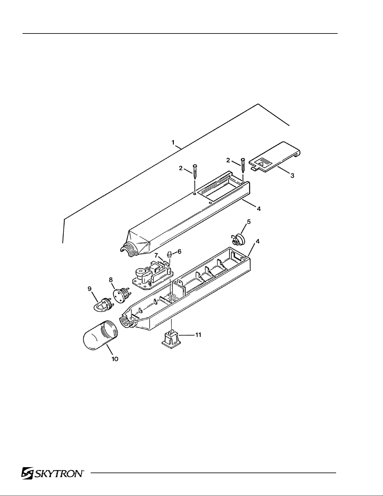
Page 12 3-2. HA30AR-WC POSITIONING WAND

Page 13
Item Part No. Description Qty.
3-2. HA30AR-WC POSITIONING WAND
1 B5-010-01-1 WAND ASSEMBLY .......................................................................................................... 1
2 B5-010-22-2 •SCREW, main case retaining ......................................................................................... 3
3 B5-010-22 •COVER, battery .............................................................................................................. 1
4 B5-010-21 •MAIN CASE (SET) .......................................................................................................... 1
5 B5-010-22-1 •SPRING, battery retaining .............................................................................................. 1
6 B5-011-83 •LED, battery indicator ..................................................................................................... 1
7 B5-010-10 •WAND CIRCUIT BOARD................................................................................................ 1
8 B5-010-09 •CONNECTOR, bulb ........................................................................................................ 1
9 B5-010-04 •STROBE BULB ............................................................................................................... 1
10 B5-010-03 •PLASTIC COVER ........................................................................................................... 1
11 B5-010-06-5 •SWITCH, push button ..................................................................................................... 1
NS B5-010-02 DRAPE, finished ............................................................................................................ A/R
NS B5-010-05 DRAPE, unfinished ........................................................................................................ A/R

Page 14
DS-2A
DS-2A
DC6V
1
2
3
4
5
6
11
7
8
9
10
13
14
15
16
17
1
DC6V
12
3-3. HA60AR-WC POSITIONING WAND

Page 15
Item Part No. Description Qty.
3-3. HA60AR-WC POSITIONING WAND
B5-012-01 PROBE, rechargable ..................................................................................................... A/R
B5-012-04 PROBE, non-rechargable.............................................................................................. A/R
1 B5-012-05 • MAIN CASE (set) ........................................................................................................... 1
2 B5-012-06 • SCREW, main case retaining ........................................................................................ 2
3 B5-012-07 • COVER, battery.............................................................................................................. 1
4 B5-012-08 • SCREW .......................................................................................................................... 2
5 B5-012-01-1 • BATTERY, AA, rechargable........................................................................................... 2
• BATTERY, AA ................................................................................................................ 2
6 B5-012-09 • RETAINER, battery ........................................................................................................ 1
7 B5-012-10 • CONNECTOR ................................................................................................................ 1
8 B5-012-11 • CIRCUIT BOARD ASSEMBLY ...................................................................................... 1
9 B5-012-12 • WASHER ....................................................................................................................... 2
10 B5-012-13 • SCREW .......................................................................................................................... 2
11 B5-012-14 • RECEPTACLE, charger............................................................................................... A/R
12 B5-012-15 • PLUG ........................................................................................................................... A/R
13 B5-012-37 • RING .............................................................................................................................. 1
14 B5-012-17 • HOLDER, bulb socket.................................................................................................... 1
15 B5-012-36 • CONNECTOR, bulb ....................................................................................................... 1
16 B5-010-04 • STROBE BULB .............................................................................................................. 1
17 B5-012-18 • COVER, bulb ................................................................................................................. 1
B5-012-19 LABEL, PN B5-012-01 ................................................................................................. A/R
B5-012-20 LABEL, PN B5-012-04 ................................................................................................... A/R
B5-012-21 LABEL, rechargable battery .......................................................................................... A/R
Page 16
3-4. HA60AR-WC CHARGING UNIT ASSEMBLY
1
2

Page 17
Item Part No. Description Qty.
3-4. HA60AR-WC CHARGING UNIT ASSEMBLY
B5-012-00 CHARGING UNIT ASSEMBLY ........................................................................................ 1
1 B5-012-00-1 • POWER SUPPLY........................................................................................................... 1
2 B5-012-00-2 • CHARGING BASE ......................................................................................................... 1

Page 18
3-5. WALL POSITIONING CONTROL
This manual suits for next models
1
Table of contents
Other Skytron Lighting Equipment manuals


