Skytron STELLAR LFS Series User manual
Page 27
OWNERS MANUA
L
LFS SERIES
REV 7-05


Page 1
TITLE PAGE
EQUIPMENT LABELS AND SPECIFICATIONS ................................................................................. 2
Special User Attention.............................................................................................................................. 3
Introduction .............................................................................................................................................. 4
Basic Lighthead Operation....................................................................................................................... 6
LightheadPositioning ............................................................................................................................... 8
IlluminationTechnique............................................................................................................................ 10
Maintenance........................................................................................................................................... 14
Repair Parts ........................................................................................................................................... 18
Hub and Radial Arm Assembly ........................................................................................................ 18
Flatscreen Bracket Assembly.......................................................................................................... 20
Height Adjustable Arm Assembly..................................................................................................... 22
TABLE OF CONTENTS
Although current at the time of publication, SKYTRON'S policy of continuous development makes this
manual subject to change without notice.
REV 7/05
Page 2
FUSE TYPE 5 AMP, SLOW BLOW TYPE
FOR DRY LOCATIONS
UNIT TO BE USED ONLY IN SPECIFIED ENVIRONMENTAL CONDITIONS
TEMPERATURE: 15 - 30 C (60 -85 F)
ATTENTION, CONSULT MANUAL FOR FURTHER INSTRUCTIONS.
INDICATES SPECIAL USER ATTENTION.
AC VOLTAGE
HUMIDITY: 30% - 60% RELATIVE HUMIDITY, NON CONDENSING
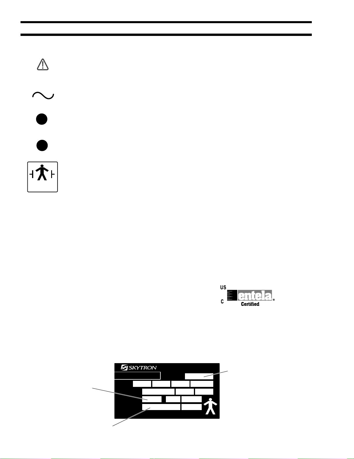
EQUIPMENT LABELS AND SPECIFICATIONS
5A
ENTELA CERTIFIED
TO UL2601-1
CAN/CSA601.1, IEC 60601-2-46
FUSE TYPE 3 AMP, SLOW BLOW TYPE
3A
CLASS I DEFIBRILLATION PROOF, TYPE B EQUIPMENT- IPX4 RATED.
INTERNALLY POWERED EQUIPMENT
TYPE B
EQUIPMENT
- GRAND RAPIDS, MI
ELECTRIC RATING CAT. NO.
SAFETY FUSE
IPXO CLASS 1
TYPE B
BULBSTYPE
24V 50W
INPUT 120V H24501
60Hz
DAI-ICHI SHOMEI CO., LTD. TOKYO, JAPAN
SERIAL NO.
MODEL
(CAT. NO.)
FUSE
TYPE
SERIAL NO.
The lighthead Data Label contains the lighthead
model number, bulb type, fuse type, electrical specifications
and product serial number.

Page 3
SPECIAL USER ATTENTION
To help assure the highest degree of operating
safety for user and patient, SKYTRON has pro-
vided precautionary instructions throughout this
manual.
As with the operation of any surgical light, all
hospital personnel should be aware that a certain
amount of care must be exercised to maintain
patient safety and to keep your SKYTRON light
fixture performing at peak efficiency.
The following is a summary of the important pre-
cautionary instructions:
WARNING
Indicatesapossibilityofpersonalinjury.
CAUTION
Indicates a possibility of damage to
equipment.
NOTE
Indicatesimportantfactsorhelpfulhints.
NOTE
To prolong bulb life, the sof-start bulb
protectioncircuitwillcauseaslightdelay
before the bubs will illuminate.
NOTE
Always make sure that the handle is
properly engaged. Failure to perform
this procedure could result in the
inadvertent release of the center focus
handle.
NOTE
SKYTRON products are guaranteed
for proper performance with the use of
genuine SKYTRON CENTER FOCUS
HANDLES. After market competitive
handles and other disposable handles
will have varying results that could
ultimatelyaffecttheproperperformance
and secure engagement of the center
focus handle. Such applications are at
the discretion of the user to ensure
patient safety.
To ensure product performance,
product longevity, and patient/staff
safety, always take caution to avoid
impact to the fixture when positioning.
NOTE
ForLFSLFSpositionthesecondarm in
the same way on the opposite side of
thetable.
NOTE
All repairs should be made using only
authorized SKYTRON replacement
parts.
WARNING
Be sure the power is turned "OFF" and
thebulbshavecooledbeforechanging.
WARNING
DO NOT attempt to remove a bulb by
pullingon the glasssurfaceor end cap.
This may cause the bulb to break off in
your hand.
NOTE
Halogen bulbs are sensitive to body
oils. DO NOT handle glass surface of
bulbasbodyoilfromfingers can create
a "hot spot" and may cause the bulb to
burn out prematurely.
NOTE
To extend the life of the bulb reflector
surface, it should not be included in
normal cleaning. It should be cleaned
only if absolutely necessary. Clean
gentlywithaclean,damp,softclothand
a mild soap solution. NO abrasives.
NOTE
The system can support and balance a
monitor weight up to 22 lbs. Exceeding
theweightwillresultinpoorbalanceand
performance.
NOTE
Refer to applicable light model
maintenanceandpartsmanualsforlight
fixture components.
CAUTION
Page 4
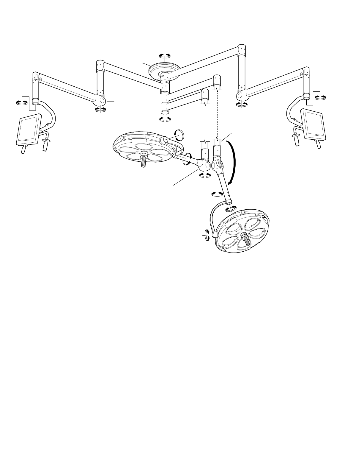
Figure 1. Light Fixture Rotation Capabilities
INTRODUCTION
The Stellar LFS series combines flatscreen moni-
tor mounting with a surgical lighting system from a
single ceiling mount.
The LFS model allows a single flatscreen monitor
mount to be combined with up to 3 separate
lightheads. The LFSLFS model combines 2
flatscreen monitor mounts with up to 2 separate
lightheads.
The LFS radial arm assembly allows up to 90" of
reachfortheflatscreenmonitorwith345°ofrotation
capability at the ceiling mount. Vertical travel of up
to 45.5" is provided.
The lighthead models available for use with the
LFS system include ST19WC, ST23, ST23TV,
ST29 and ST29TV. The ST19WC model is fixed
focus, the remaining models are all focusable.
345˚
PITCH
360˚
CEILING
COVER
360˚ ROLL
360˚
ROLL
360˚
110˚
VERTICAL
TRAVEL
PITCH
360˚
VERTICAL
SUPPORT
TUBE
VERTICAL
SUPPORT
TUBE
BALANCE
MECHANISM
BALANCE
MECHANISM
340˚
340˚
360˚
540˚ 540˚
360˚

Page 5
STERILIZABLE
FOCUS/POSITIONING
HANDLE
NON-STERILE
SIDE FOCUS KNOB
The Stellar series surgical lighting system from
SKYTRON features fully adjustable positioning
and focus control for its cool, color-corrected,
multiplebulb,lightsource.Combinationsofvertical
positioningandmultiplerotationalcapabilitiesallow
the single, dual or triple lighthead models virtually
limitlesspositioning.
Thefixturesaresinglepointceilingmountedwitha
continuous 360 degree rotation capability at the
ceiling mount end of the radial support arm. See
figure 1. The balance mechanism which is at-
tached to the radial arm by a vertical support tube,
providesthelightheadanadditionalcontinuous360
degree rotation point. The balance mechanism is
an enclosed spring tension system. This allows
verticalmovementofthe lighthead while maintain-
ingthelightheadpositionwithoutdrifting.Theyoke
provides additional 360 degree rotation points for
lighthead pitch and roll.
The Stellar fixtures have a lighthead vertical travel
capability of 110°.
The adjustable focus mechanism which optimizes
thelightoutputbysuperimposingallthelightbeams
into a single spot can be operated by non-sterile
personnelusingthelightheadmountedfocusknob.
All lightheads also have a removable, sterilizable,
focus/positioning handle. This allows all final posi-
tioning and focus adjustments or changes to be
precisely done by the surgeon. See figure 2.
Figure 2. Focus Adjustments
Page 6
BASIC LIGHTHEAD OPERATION
Use the following instructions to operate the light
fixture:
1.Positionthelightheadsasrequiredbygrasp-
ing the lighthead positioning handles and moving
the lighthead to the desired position. See figure 3.
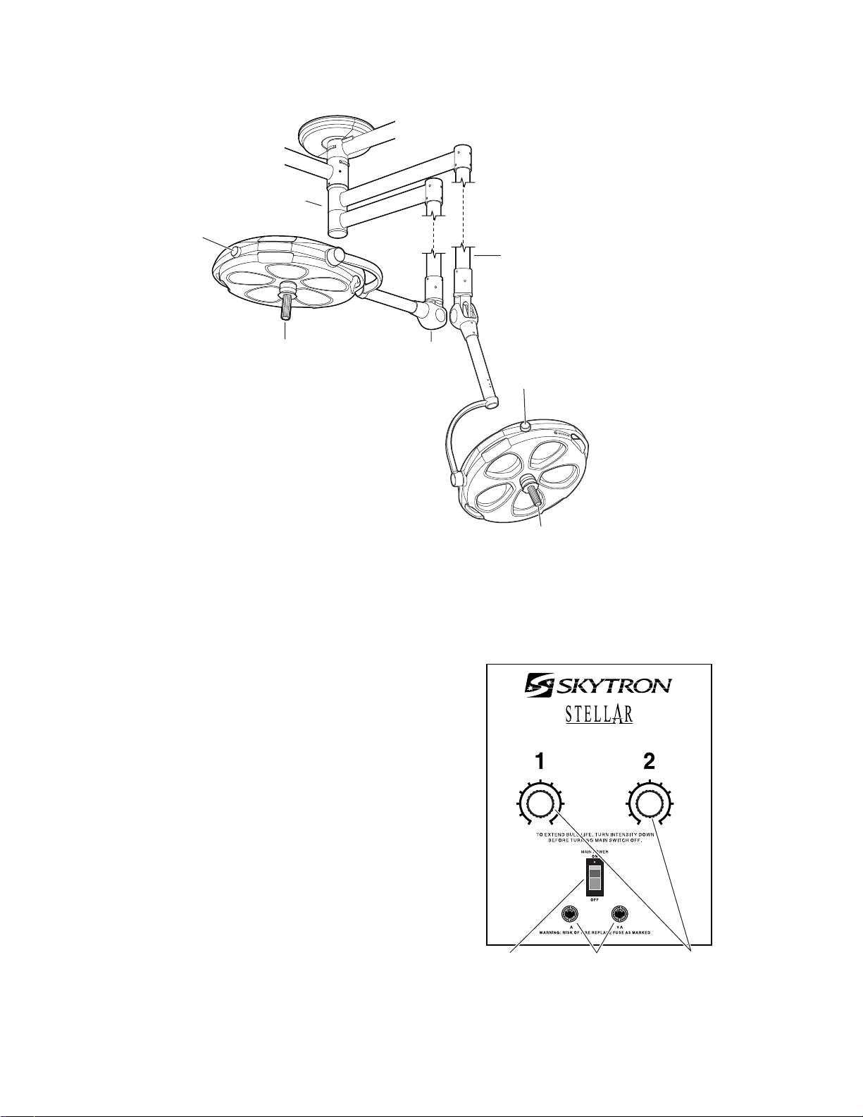
2.Turnthelightfixturemainpowerswitch"ON"
at the wall mounted control box and select the
desired intensity for each lighthead as required.
See figure 4. The mid-range position will provide
adequate illumination for most procedures. Full
intensity will usually only be required for extreme
deep cavity cases.
NOTE
To prolong bulb life, the sof-start bulb
protectioncircuitwillcauseaslightdelay
before the bulbs will illuminate.
Figure 3. Dual Lighthead Fixture
Figure 4. Wall Mounted Control Box
SAFETY
FUSES
MAIN
POWER
SWITCH
6
010
19
28
37
456
010
19
28
37
45
INTENSITY
CONTROL
KNOBS
5
RADIAL ARM
ASSEMBLY
STERILIZABLE
FOCUS/POSITIONING
HANDLE FOCUS
KNOB
FOCUS
KNOB VERTICAL
SUPPORT
TUBE
BALANCE
MECHANISM
STERILIZABLE
FOCUS/POSITIONING
HANDLE

Page 7
3. When the surgeon is ready to use the light,
installthesterilizedcenterfocus/positioninghandle
using the following procedure. See figure 5. Be
sure handle is properly secured before using the
lighthead. Possible injury to patient or staff could
result if a handle is not installed properly.
a. Insert the handle into the lighthead at-
tachment ring.
NOTE
Always make sure that the handle is
properly engaged. Failure to perform
this procedure could result in the
inadvertent release of the center focus
handle.
b. Push the handle in, turn it right and left, and pull
thehandleouttobecertainthatitislocked(PUSH-
TWIST-PULL). A distinct click can be heard when
the handle is properly engaged.
c. To remove the handle, push the release
button and pull the handle out.
Figure 5. Center Focus/Positioning Handle
Installation
STERILIZABLE
HANDLE
HANDLE
RELEASE
BUTTON
4. Adjust the focus by moving either the non-
sterile focus knob or the (sterilized) center focus
handle until all of the light beams converge on the
surgical site forming a single bright spot of light.
5.Forlowanglelightingapproach,thelighthead
will move 90° below horizontal. Pull the lighthead
down by the positioning handles or the (sterile)
positioning/focushandle.
In the presence of flammable anesthetics, DO
NOT allow the lighthead to travel below 60 inches
from the floor.
6. When the light is no longer required, return
the lighthead to its full up position. Decrease the
intensityatthewallcontrol,andturnthemainpower
switch "OFF".
NOTE
SKYTRON products are guaranteed
for proper performance with the use of
genuine SKYTRON CENTER FOCUS
HANDLES. After market competitive
handles and other disposable handles
will have varying results that could
ultimatelyaffecttheproperperformance
and secure engagement of the center
focus handle. Such applications are at
the discretion of the user to ensure
patient safety.

Page 8 LIGHTHEAD POSITIONING
CAUTION
To ensure product performance,
product longevity, and patient/staff
safety, always take caution to avoid
impact to the fixture when positioning.
The lightheads can be most effectively positioned
by using the following procedures:
1.Graspthepositioninghandlesonthelighthead
and pull the lighthead down to shoulder height.
Keepthe lightheadatapproximatelya45°angleto
easily position the support yoke. See figure 6.
General
To obtain the maximum benefit from your
SKYTRON surgical lighting system, the following
suggestions are offered as a guide for lighthead
positioning. Personnel who are trained in proper
lightingtechniques canplanandsetupthe lighting
arrangements prior to the arrival of the patient.
Factors which should be considered when
prepositioning surgical lights are:
-Specific procedure to be done
-Patient position during procedure
-Position of surgical team
-Location of instrument trays or tables
-Location of IV stands
-X-ray equipment and personnel
-Anesthesia equipment and personnel
-Angulation and size of surgical cavity
Surgical Table Placement
For most procedures the surgical table should be
located with its center point directly under the light
fixture’s ceiling mount.
Pre-Positioning The Lighthead
Surgicallightpositioningrequirementschangenot
onlyfromproceduretoprocedure,theyalsochange
from surgeon to surgeon. Final light positioning
and adjustment will be directed or done directly by
the surgeon. The objective of prepositioning is to
requireaminimumoffinaladjustmentsafterarrival
of the patient. The non-sterile focus control should
be located where it can be reached by non-sterile
personnel and the sterile positioning/focus handle
where they can be reached by the surgeon. Use
extreme care when prepositioning lightheads.
Bumpinglightheadsintooneanother,intowalls,or
other equipment may alter bulb alignment which
affects proper focus adjustment.
90˚
RADIAL ARM
Figure 7.
Figure 6.
2. Using the positioning handles, rotate the
lighthead around the vertical support until the
lighthead is at an approximate 90° angle to the
radial arm. See figure 7.
POSITIONING
HANDLE
SUPPORT
YOKE

Page 9
Figure 8. Main Lighthead Radial Arm
Positioning
5. With the radial arm in proper position, rotate
the lighthead to the desired position and install the
sterile positioning/focus handle. Refer to sterile
handleinstallationprocedure.
6. Grasp the positioning handles, place the
lightheadat anangle andmovethe lighthead toits
full up position.
90˚
ABDOMINAL
CHEST
PELVIC
HIP
ORTHO
OB/GYN NEURO
EENT
DOCTOR SIDE OFTABLE
45˚ 45˚
180˚ 180˚
3.Placetheradialarminthedesiredpositionby
pushing or pulling the lighthead by the positioning
handles as you walk around the surgical table.
4. Refertofigure8toapproximatethedesired
radial arm position for locating the lighthead over
thepatient.
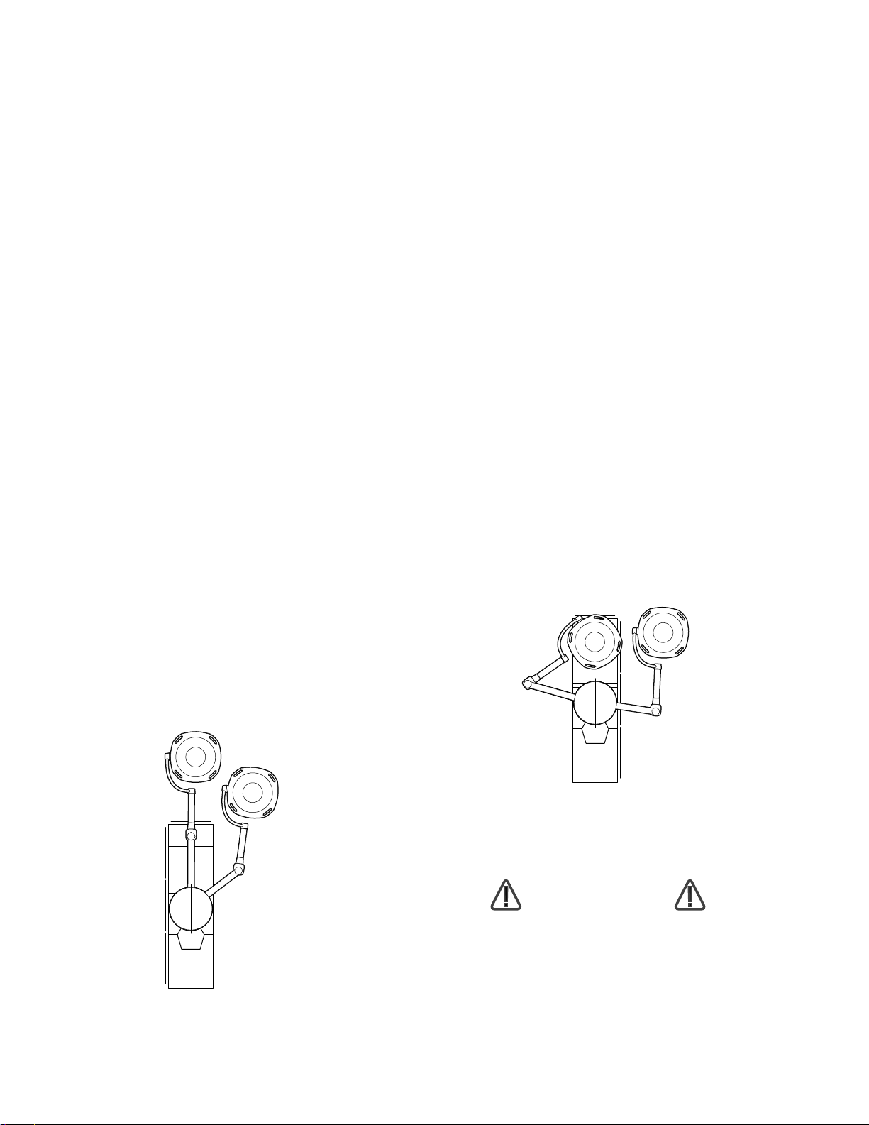
Flatscreen Monitor Positioning
The upper radial arm of the flatscreen monitor
mount should be pre-positioned on the opposite
sideofthetablefromthesurgeonatapproximately
90° from the table center line. See figure 9.
Figure 9.
The lower arm should be positioned under the
upperarm.Inthispositionthemonitorcanbeeasily
movedupordownthefulllengthofthetablewithout
interfering with the lightheads. The monitor can be
pushed up out of the way until it is needed.
Twosterilizablehandlesareprovidedforfinalmoni-
tor positioning or for changes required during the
procedure. Prior to the start of the procedure the
sterilizable handles can be installed. Insert the
sterile handles into the receptacle and turn clock-
wise until tight.
NOTE
ForLFSLFSpositionthesecondarmin
the same way on the opposite side of
thetable.
Page 10
Torso Area
For most chest and abdominal procedures, posi-
tion the large lighthead directly over the surgical
site. See figure 11. Position the radial arm on
approximately a 45° angle from the surgical table
centerline.Thispositionwilllocatethesterilefocus/
positioning handle on the lighthead where it can
easily be reached by the surgeon. The focus con-
trol will be where it can easily be reached by non-
sterile personnel. Position the satellite lighthead,
dependingonlightingneeds,toaugmentthelarger
lighthead.
Figure 11.
ILLUMINATION TECHNIQUE
Maximumillumination,shadowreduction,andpos-
sible obstruction by the surgeon or surgical staff
are also major concerns for lighthead positioning.
The following examples are offered as a basic
guide for lighthead placement for large diameter/
satellite,duallighthead,or triple lighthead fixtures.
Large Diameter/Satellite Lighthead
Positioning
The large diameter lighthead should be pre-posi-
tioned over the surgical site. The satellite can be
usedoneithersideofthesurgeonforaugmentation
and shadow control.
The large lighthead should be positioned perpen-
dicular to the bottom of the surgical cavity.
Head
To illuminate the head area, position the large
diameter lighthead radial arm parallel to the table
centerline. See figure 10. Position the lighthead
behindthesurgeon.Tiltthelightheadtothedesired
positionusing pitchaxismovement. Thiswillallow
the multiple light sources of the lighthead to pass
aroundtheheadandshouldersofthesurgeonand
at the same time permit adequate head clearance
for the surgeon.
Tilt the lighthead to position the focus control knob
where it can be easily reached by non-sterile
personnel.
Positionthesatelliteto the leftor right accordingto
surgeon preference. This allows a second light
source to come from another angle which will help
eliminate obstructions or shadows.
Figure 10.
CAUTION
To ensure product performance,
product longevity, and patient/staff
safety, always take caution to avoid
impact to the fixture when positioning.

Page 11
Some procedures, such as hip pinnings, require
bothlightheadstobeonthesamesideofthetable.
See figure 13. In this position the lightheads are
behind and adjusted to project light over the head
and shoulders of the surgeon. Both lightheads are
easily reached for adjustment by non-sterile per-
sonnel.
Figure 14.
Perineum
Thelargediameterlighthead should bepositioned
at the end of the table for perineal procedures.
Locatetheradialarmdirectlyinlinewiththecenterline
of the table. Once thesurgeonhasassumeda
seated position, the lighthead can be pulled down,
angled, and adjusted to provide the necessary
illumination over the surgeon’s head and shoul-
ders. See figure 14. The satellite lighthead radial
arm should be positioned approximately 90° from
theotherradialarm.Positionthesatellitelighthead
totherightorleftofthelargelightheadaccordingto
surgeon preference. In this position, the focus
knobsofbothlightheadsarelocatedforeasyreach
by non-sterile personnel.
Figure 13.
Figure 12.
In some cases such as cholecystectomies and
totalabdominalhysterectomies,thesurgicalcavity
may be angled. In cases such as this, the large
lighthead should be angled so that the face of the
lighthead is perpendicular to the bottom of the
surgical cavity. See figure 12.

Page 12
Dual 23" Diameter Lighthead Positioning
Fixtures containing dual 23" diameter lightheads
require some special positioning considerations.
Thesmalldiameterofthelightheadsallowsthelight
sourcetobemoreeasilyobstructedbythesurgical
staff. It is very important that the surgical site
remain illuminated even though the head and
handsofthesurgeonandthesurgical staff may be
directly in the central light beam path. In order to
minimize shadowing, thelightheadsshouldbepo-
sitionedsothattheirlightbeamsareangledintothe
surgical cavity. Regardless of the surgical site,
these lights should be positioned to maintain an
angleofapproximately30°aboutanimaginaryline
runningperpendiculartothebottomofthesurgical
site. See figure 15.
Figure 16.
Figure 15.
Tilting the lightheads will give a larger light beam
angle. See figure 16. Final positioning and focus
adjustmentscanbedonebythesurgeonusingthe
sterile focus/positioning handles. Focus controls
shouldbepositionedwhereeasilyreachedbynon-
sterile personnel.
30˚ 30˚
30˚
CAUTION
To ensure product performance,
product longevity, and patient/staff
safety, always take caution to avoid
impact to the fixture when positioning.

Page 13
Figure 18.
Beyond the focal point, the light beams spread out
like an inverted cone and will more evenly spread
the light throughout the bell-shaped cavity.
Bell-Shaped Cavities
For most surgical procedures the lighthead will be
properlyfocusedwithallthelightbeamsconverged
in one spot at the bottom of the surgical cavity.
However, in the case of a bell-shaped cavity (for
example - total abdominal hysterectomy on an
obesepatient),focusingatthebottom of the cavity
may cause more shadow problems. The focal
point for the light beams should be above the
bottom of the cavity. See figure 18.
Triple Lighthead Positioning
Triple lighthead systems will either consist of a
large diameter lighthead with two 23" satellites or
three23"lightheads.There are twobasic position-
ing strategies that can be used to obtain the best
illumination possible. The first is to align all three
lightheads to the centerline of the table with the
largelightheaddirectlyoverthecenterofthesurgi-
cal site. The second is to cluster the lights in a
circular arrangement over the surgical site with
each lighthead about 120° away from each other.
Thewholeclustershouldbepositionedtominimize
interference with the head and shoulders of the
surgical staff. See figure 17.
Figure 17.
Whenanangledcavity is to be illuminated,atleast
one of the lightheads should be positioned to be
perpendicular to the bottom of the cavity.
For head and perineal work, the lights should be
positionedastheywouldforadualsystembutwith
a satellite on each side of the surgeon.
Other Illumination Considerations
Closeattentiontosurgicallightintensity during the
caseas wellasgoodqualitygeneralilluminationin
theroomwillhelptominimizeeyefatigueofsurgical
personnel.
Dark surgical drapes will help to reduce reflec-
tance.Whitedrapesshouldbeavoidedat all times
because of high reflectance.
The use of matte and satin finish instruments and
retractors also helps to reduce eye fatigue.
120˚ 30˚
30˚
30˚
120˚
120˚
LIGHT
BEAMS
FOCAL
POINT
BELL SHAPED
CAVITY

Page 14 MAINTENANCE
General
Toinsureproperoperationandtoextendthelifeof
your SKYTRON surgical lighting system, the fol-
lowing preventive maintenance procedures are
recommended.
NOTE
All repairs should be made using only
authorized SKYTRON replacement
parts.
Daily Maintenance
Daily or between cases, the lighthead exterior
should be wiped down with a mild cleaning agent
which will not affect the painted or acrylic parts.
•Inspect the light heads and fixture for visable
damage.TeportdamageimmediatlytoSKYTRON
representative.
•Avoid the use of cleaning solutions which contain
high concentrations of alcohol, ethelene glycol,
phenol, iodophors, or glutaraldehyde based
disinfectancts. Some degree of staining, pitting,
peeling and discoloration may occur if these are
used.
Alwaysconsultwiththemanufacturerof the clean-
ing agent for proper application and use. Always
spot test on an inconspicuous area before use.
•Avoid personal injury. Do not attempt to clean
lighthead unless power is turned off at wall control
and fixture has sufficiently cooled.
•Avoidusingexcessiveamountsofspraycleaners
near top cover vents. Leakage of fluids into the
interioroflightheadmaycausecorrosionofelectri-
cal components.
•Periodically the filter/diffuser assemblies should
be removed and dusted with a clean cloth or
washed and air dried as a complete assembly.
•DO NOT operate lights without the filter/diffuser
assemblies in place.
•Use plexiglass cleaners, DO NOT use alcohol
based cleaners on the acrylic diffusers.
Sterilization
Recommended sterilization parameters for
sterilizablehandle:
a. Prevac, 270° F, 4 minutes
b. Gravity, 250° F, 30 minutes
c. Flash, 270° F, 3 minutes
Always consult current AORN journal recommen-
dations for proper sterilization procedures.
Adjustments
As part of a regular preventive maintenance pro-
gram, it is suggested that a check of the various
positioning axes be made to verify correctness of
tensionadjustment.Ifany driftisnoticed,allthatis
usually necessary is a minor adjustment. Read-
justment should be made as per the appropriate
instructionscontainedinthe Maintenance and Ad-
justment Manual for the specific model lighthead.
Also, during a scheduled cleaning of the lighthead
interior, lubrication of the various moving parts is
desirable.
Bulb Changing
Since SKYTRON Surgical Lights contain multiple
bulbs,itwouldnotnormallybenecessarytochange
aburnedoutbulbduringasurgicalprocedure. The
loss of one or even three bulbs in a large diameter
lightheadmaybe completelyunnoticedduringuse.
To replace a bulb, use the following procedure:
WARNING
Be sure the power is turned "OFF" and
the bulb has cooled before changing.
1. Hold the diffuser/filter assembly with one
hand, loosen the "1/4-turn" screw and lower the
diffuser/filter assembly. See figure 19.

Page 15
WARNING
DONOT attempttoremovethebulbby
pullingon theglasssurfaceorendcap.
This may cause the bulb to break off in
your hand.
2. Using caution not to touch the reflector
surface, hold the bulb by the base and pull it out.
See figure 20. Slightly working the bulb back and
forth may aid in bulb removal.
Figure 19.
Figure 20.
NOTE
Halogen bulbs are sensitive to body
oils. DONOThandletheglasssurface
ofthebulbasbodyoilfromyourfingers
can create a "hot spot" and may cause
the bulb to burn out prematurely.
3. Holding the bulb by the base, plug it directly
intothesocket.Donottouchtheglassportionofthe
bulb reflector surface with your fingers. This can
best be done by using the plastic wrapper that the
bulb is packaged in or a clean cloth wrapped
aroundthebaseofthebulbwheninstalling.Besure
bulb base is properly seated in the connector to
insure proper focus alignment.
NOTE
To extend the life of the bulb reflector
surface, it should not be included in
normal cleaning. It should be cleaned
only if absolutely necessary. Clean
gentlywithaclean,damp,softclothand
a mild soap solution. NO abrasives.
4. Replace the diffuser/filter assembly by plac-
ing the tab into the lighthead face. Place the
assembly in position and secure it with the "1/4-
turn" screw.
1/4TURN
SCREW
REFLECTOR
SURFACE
END
CAP
BASE

Page 16
LFS Height Adjustable Arm Tension
Adjustment
a. Checktheverticaltensionadjustmentofthe
Height Adjustable Arm for its capacity to support
the flatscreen monitor throughout its range of mo-
tion. The monitor should move freely yet maintain
its selected position without drifting. If an adjust-
ment is necessary, refer to figure 13 and proceed
as follows:
NOTE
TheSystemcansupportandbalancea
monitor weight up to 22 lbs. Exceeding
the weight will result in poor balance
and performance.
Figure 21
b. Remove the cover plate on the top of the
Height Adjustable Arm for access to the tension
adjustmentnut. Inserta1/8"pinpunchintoaholein
the adjustment and turn the nut as required to
achieve proper tension - clockwise to increase
tension, counterclockwise to decrease tension.
Replace access cover when adjustment is com-
plete.
c. Check the adjustment for the flatscreen
monitorpitchaxis.Themonitorshouldmovefreely
yetmaintainitsselected positionwithoutdrifting.If
an adjustment is necessary, refer to figure 14 and
proceed as follows:
Figure 22
d. Loosen set screw on trunnion nut, insert a
1/8"pinpunchintoholeoppositesetscrewlocation
and adjust trunnion nut as required - clockwise to
increase tension, counter clockwise to decrease
tension. Tighten set screw when adjustment is
complete.
e. Forfineadjustment,rotatethemonitordown-
ward until the adjustment nut is visible on the
tension spring assembly. Using a pin punch, turn
theadjustmentnutuntilpropertensionisachieved.
COVER PLATE
1/8" PIN PUNCH
ADJUSTMENT
NUT
PIN PUNCH
1/8"PIN
PUNCH
ADJUSTMENT NUT
TRUNION
NUT
SET SCREW
TENSION SPRING

Page 17
A regular program of preventive maintenance will
increase the life of your equipment and keep it
operating at peak performance.
Maintenance can be performed by authorized,
trained maintenance personnel using SKYTRON
authorized replacement parts and service tech-
niques. Service instructions and parts are avail-
able from SKYTRON.
Preventive Maintenance contracts are available
through your local SKYTRON representative.
To obtain service instructions, replacement parts,
factory service or preventive maintenance con-
tracts,contacttheSKYTRONrepresentativelisted
below.
Or contact:
SKYTRON
5000 36th Street S.E.
Grand Rapids, MI 49512
1-800-SKYTRON (1-800-759-8766)
Fax. 1-616-957-5053
Original Print Date 1/05
NOTE
Refer to applicable light model
maintenanceandpartsmanualsforlight
fixture components.

Page 18 REPAIR PARTS
1. HUB AND RADIAL ARM ASSEMBLY
1
1
24
25
1
8
8
18
19
8
8
20
20
22
23
111003.01
20
20
21
17
11
12
10
7
6
9
13
14
15
516
2
3
4
26
27
Table of contents
Other Skytron Lighting Equipment manuals

Popular Lighting Equipment manuals by other brands


Collingwood Lighting
Collingwood Lighting Salvus Surface EMSBSQEM installation instructions

Elation
Elation Rayzor Q7 user manual

Cooper Crouse-Hinds
Cooper Crouse-Hinds Champ VMV High Wattage Series quick start guide

Weda
Weda B600 Service manual

Soundoff Signal
Soundoff Signal Intersector ENT3 3 Series manual

Infinity
Infinity TCYC-7 manual

GRILL MEISTER
GRILL MEISTER 360468 2007 Operation?and safety

GNC
GNC HEAVEN S Installation operating & maintenance manual

Solem
Solem WF-OL Quick installation guide

Eye Hortilux
Eye Hortilux LED 350-ES installation instructions

Lightolier
Lightolier Baselyte-BSL8 datasheet

Steren
Steren MODLED-300/RGB instruction manual