manuals.online logo
Brands
  1. Home
  2. •
  3. Brands
  4. •
  5. Tranberg
  6. •
  7. Lighting Equipment
  8. •
  9. Tranberg TEF 2870 User manual

Tranberg TEF 2870 User manual

R. Stahl Tranberg AS
E[email protected] | stahl-tranberg.com
Main office: Strandsvingen 6 | N-4032 Stavanger | Norway | T+47 51 57 89 00 | F+47 51 57 89 50
Office Oslo: Luhrtoppen 2 | N-1470 Lørenskog |Norway | T+47 24 08 44 10
WARNING!
DO NOT OPEN, MAINTAIN OR SERVICE IN AN AREA
WHERE AN EXPLOSIVE ATMOSPHERE MAY BE
PRESENT.
IMPORTANT
Read this instruction carefully before installing the
product
COPYRIGHT
©Tranberg AS
The information contained in this document remains the
sole property of Tranberg AS. No part of this document
may be copied or reproduced in any form or by any
means, and the information contained within it is not
to be communicated to a third party, without the prior
written consent of Tranberg AS. The document, or any
part of it, may not be translated to any other language
without the written approval from Tranberg AS.
DISCLAIMER
Tranberg AS endeavors to ensure that all information in
this document is correct and fairly stated, but does not
accept liability for any errors or omissions.
SAFETY PRECAUTIONS
Note that changes made to the product and/or installation
of components which do not conform to the manufactur-
er’s specification, may be a safety violation. The manufac-
turer will in no circumstance be held responsible for such
activity. For your health and safety, always use safety gear
suited for the task. Be certain to follow codes, regulations
and/or specific procedures that are related to the installa-
tion.
NAVIGATION LIGHTS
TEF 2870 ExNAVIGATION LIGHT
ZONE 2 & SAFE AREA
USER MANUAL
Subject to change without prior notice TUM4834 REV. K 03.08.2018
TEF 2870 Ex NAVIGATION LIGHT USER MANUAL
INTRODUCTION
Thank you for purchasing this product!
For installation, maintenance and assurance of a long life
of this product, please follow this manual.
CONTENT IN BOX
The product is fully assembled, and ready for installation.
SAFETY PRECAUTIONS
Note that changes made to the product and/or installation
of components which do not conform to the approval,
may be a safety violation. The manufacturer will in no
circumstance be held responsible for such activity. For
your health and safety, always use safety gear suited for
the task. Be certain to follow codes, regulations and/or
specific procedures that are related to the installation.
TOOLS REQUIRED
Regular tools required for installation.
• Wrench(es) suitable for selected M10 bolts for fixing
navigation light to mast / ships structure.
• Flat screwdriver for opening junction box.
• 27mm wrench for installing of cable gland.
• Small flat screwdriver for terminating wires.
IMPORTANT INFORMATION
The navigation lights are supplied with galvanic isolators.
These should be placed between the navigation light and
the wall, thus preventing corrosion to either. There should
be used acid resistant stainless steel fixing screws/bolts.
Never paint navigation light or any of its components. Use
only spare parts as described.
Gasket for junction box shall be replaced at intervals of one
year. (Part No. 5003 0164). Gasket shall be of same type as
original. One replacement gasket is included in shipment.
The navigation light should be inspected according to
Company routines. The manufacturer suggests regular
check for water intrusion / condensation which should
be removed immediately. When cleaning, use only mild
detergents. Alcohol or petroleum based products may
damage lens, paint or plastic components.
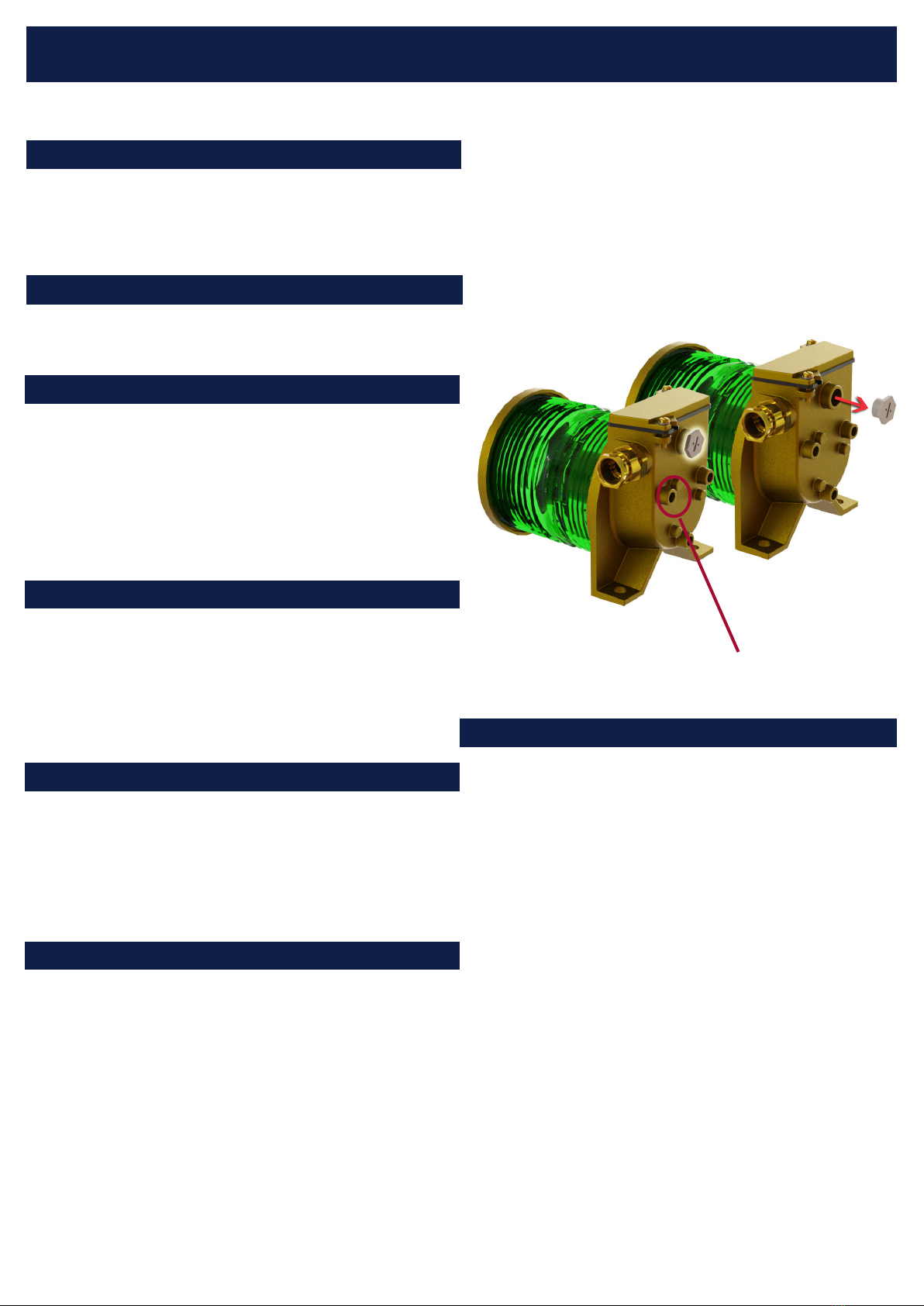
At intervals according to company routines, the restricted
breathing properties should be verified. Remove stopping
plug at test port (PG9). See illustration below.
INSTALLATION INSTRUCTIONS
The navigation light should be installed according to IMO
regulations and other relevant rules and regulations for
electrical installations onboard ships.
Consider the difference in material between the navigation
light (seawater resistant brass) and the wall/mast it is to be
installed on. Use galvanic isolators whenever there is a
risk of corrosion.
• Fix navigation light to mast / ships structure using 2x
M10 bolts (not supplied). Use acid resistant screws/
bolts. Tight firmly, max. 25 Nm.
• Open junction box, install and secure electrical cable.
The cable must be clamped near up to the navigation
light according to relevant rules and regulations for elec-
trical installations onboard ships.
• Connect electrical wires. Max. 2.5mm2. Strip length
8mm. Tightening force 0.6-0.8nm. Connect ground wire
to M5 earth screw in junction box.
• Screw on junction box lid. Max. tightening force: 5 Nm.
Make sure that gasket is centered and covering the
whole perimeter.
• External bonding conductor. Connect bonding wire to
point shown in illustration above. M8 screw.
For mounting and screening of side navigation lights, see
illustration next page.
MAINTENANCE INSTRUCTIONS
Connect pressure meter / vacuum pump and conduct test
according to IEC 60079-15(2010) 23.2.3.2.1.1. Note: PG9
gland for connection of Ø3.5-8mm hose is included in
shipment. Note: According to approval, test of restricted
breathing properties is not required.
Point for connecting bonding wire
TEF 2870 Ex NAVIGATION LIGHT USER MANUAL
B
B
A
SCREENING DATA FOR SIDE
Formula:
A B C* D E F* G* X* Y* Z*
TEF 2870 <B*2 >=200 175 >=Cx2 67-(0,026xD) 700 465 55 200 210
Recommended practical measurements:
A B C* D E F* G* X* Y* Z*
TEF 2870 400 200 175 350 58 700 465 55 200 210
NOTE:
All measurements in millimeters
All tolerances +/-1mm
Minimum measurements indicated by an asterix (*)
280A105557
Recommended mounting
method of double tier
navigation lights.
LAMP REPLACEMENT
WARNING - DO NOT OPEN, MAINTAIN OR SERVICE IN
AN AREA WHERE AN EXPLOSIVE ATMOSPHERE MAY BE
PRESENT.
Use a 19mm wrench to screw off lid. Twist off lamp and
replace. Screw lid back on. Tightening force: 5 Nm.
280A4966
R. Stahl Tranberg AS
E[email protected] | stahl-tranberg.com
Main office: Strandsvingen 6 | N-4032 Stavanger | Norway | T+47 51 57 89 00 | F+47 51 57 89 50
Office Oslo: Luhrtoppen 2 | N-1470 Lørenskog |Norway | T+47 24 08 44 10
SPARE PARTS
TEF 2870 Ex NAVIGATION LIGHT USER MANUAL
Description Part No.
Light source, P28S 24V 40W 9400 049
Light source, P28S 230V 65W 9400 052
Mounting bracket for 1” pipe 0000 2600
Mounting bracket for 2” pipe 0000 2440
Lamp holder P28S 5088 0019
Gasket, junction box 5003 0164
O-ring, top lid 5000 0051
Cable gland M20 M20 Ø9,0 - 14,3mm 6222 010
Gland PG9 Ø3.5-8mm for restricted breathing test 5656
Material: Brass, lens of through coloured glass
Input voltage: According to installed light bulb. Max. 230V.
Light source: 40W for 24V versions.
65W for 115/230V versions.
Lamp base: P28S
Power comsumption: 40-65 Watt
Ingress protection: IP66
Cable gland: M20 Ø9,0 - 14,3mm
Area of use: Ex zone 2 and safe area.
Ex classification: II3G Ex nR IIC Gc T5
Operating temperature: -52°C to +50°C
Certificate No. EC type examination MEDB000025U (DNV-GL)
EC Quality System MEDD000006D (DNV-GL)
PRESAFE 14 ATEX 5436X
IECEx PRE 14.0055X
Special conditions: Resistance to impact is tested
with reduced values, according to EN 60079-0
26.4.2, “low risk of mechanical damage”.
Compliance standards: COLREG 72 as amended, Annex I/14, IMO Res
A.694(17), IMO Res MSC.253(83) EN 60079-
0:2012, EN 60079-15:2010
TECHNICAL DATA

Other Tranberg Lighting Equipment manuals

Tranberg TEF 9970 LED User manual

Tranberg

Tranberg TEF 9970 LED User manual

Tranberg TEF 2880 User manual

Tranberg

Tranberg TEF 2880 User manual

Tranberg TEF 2440 User manual

Tranberg

Tranberg TEF 2440 User manual

Tranberg TEF 2441 User manual

Tranberg

Tranberg TEF 2441 User manual

Tranberg STAHL TEF 2457 User manual

Tranberg

Tranberg STAHL TEF 2457 User manual

Tranberg TEF 2502 User manual

Tranberg

Tranberg TEF 2502 User manual

Tranberg TEF 2440 User manual

Tranberg

Tranberg TEF 2440 User manual

Tranberg TEF 2460 LED User manual

Tranberg

Tranberg TEF 2460 LED User manual

Tranberg TEF 2850 User manual

Tranberg

Tranberg TEF 2850 User manual

Tranberg TEF 2940 User manual

Tranberg

Tranberg TEF 2940 User manual

Tranberg TEF 9980 User manual

Tranberg

Tranberg TEF 9980 User manual

Popular Lighting Equipment manuals by other brands

GE Tetra PowerMAX GEPM71-W1 installation guide

GE

GE Tetra PowerMAX GEPM71-W1 installation guide

Prilux Nantes instruction manual

Prilux

Prilux Nantes instruction manual

Contest VERSATILE COLOR VBAR-50RGBL user guide

Contest

Contest VERSATILE COLOR VBAR-50RGBL user guide

DTS PAR64Ip66 watertight user manual

DTS

DTS PAR64Ip66 watertight user manual

Steamist TSCH Installation and operating instructions

Steamist

Steamist TSCH Installation and operating instructions

Candela ELE installation manual

Candela

Candela ELE installation manual

Intex Quick-Fill AP620-3 owner's manual

Intex

Intex Quick-Fill AP620-3 owner's manual

Alfaled AFR-6 instruction manual

Alfaled

Alfaled AFR-6 instruction manual

Western Technology 9610A operating instructions

Western Technology

Western Technology 9610A operating instructions

One Stop Gardens 57715 Owner's manual & safety instructions

One Stop Gardens

One Stop Gardens 57715 Owner's manual & safety instructions

Ledj Archi BAR 48 user manual

Ledj

Ledj Archi BAR 48 user manual

Philips LCN9620 user manual

Philips

Philips LCN9620 user manual

ARCHIPELAGO LIGHTING LEMX installation guide

ARCHIPELAGO LIGHTING

ARCHIPELAGO LIGHTING LEMX installation guide

Somogyi Elektronic home DLFJ400F quick start guide

Somogyi Elektronic

Somogyi Elektronic home DLFJ400F quick start guide

ATG Electronics UFO user guide

ATG Electronics

ATG Electronics UFO user guide

Moree 07-01-01 instruction manual

Moree

Moree 07-01-01 instruction manual

NENKO 20151111 quick start guide

NENKO

NENKO 20151111 quick start guide

American DJ Revo III User instructions

American DJ

American DJ Revo III User instructions

manuals.online logo
manuals.online logoBrands
  • About & Mission
  • Contact us
  • Privacy Policy
  • Terms and Conditions

Copyright 2025 Manuals.Online. All Rights Reserved.