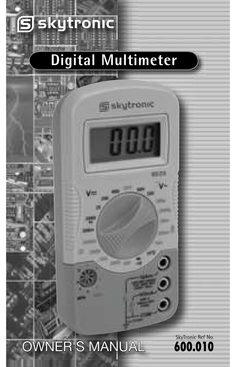
SKYTRONIC 600.219 User manual

DIGITAL MULTIMETER
600.219
600.524
Gebruiksaanwijzing
Instruction Manual
Mode d’Emploi
Gebrauchsanleitung
Brugsanvisning


Read this owner’s manual thoroughly before use.
SAFETY INFORMATION
The digital multimeter has been designed according to IEC-1010
concerning electronic measuring instruments with an over voltage
category (CATI) and pollution degree 2.
ELECTRICAL SYMBOLS
AC (Alternating Current)
DC (Direct Current)
Important safety information. Refer to the manual.
Dangerous voltage may be present.
Earth ground
Fuse
Conforms to European Union directives
Double insulated
Do not attempt to make any repairs yourself. This would invalid your warranty.
Do not make any changes to the unit. This would also invalid your warranty.
The warranty is not applicable in case of accidents or damages caused by
inappropriate use or disrespect of the warnings contained in this manual.
SkyTronic UK cannot be held responsible for personal injuries caused by a
disrespect of the safety recommendations and warnings. This is also applicable to
all damages in whatever form.

WARNING
To avoid possible electric shock or personal injury, follow these
guidelines:
•Do not use the meter if it is damaged. Before you use the
meter, inspect the case. Pay particular attention to the
insulation surrounding the connectors
•Inspect the test leads for damaged insulation or exposed
metal. Check the test leads for continuity. Replace damaged
test leads before you use the meter.
•Do not use the meter if it operates abnormally. Protection
may be impaired. When in doubt, have the meter serviced.
•Do not operate the meter around explosive gas, vapor, or
dust.
•Do not apply more than the rated voltage, as marked on the
meter, between terminals or between any terminal and earth
ground.
•Before use, verify the meter's operation by measuring a
known voltage.
•When servicing the meter, use only specified replacement
parts.
•Use with caution when working above 30V AC RMS, 42V
peak, or 60V dc. Such voltages pose a shock hazard.
•When using the probes, keep your fingers behind the finger
guards on the probes.
•Connect the common test lead before you connect the live
test lead. When you disconnect test leads, disconnect the live
test lead first.
•Remove the test leads from the meter before you open the
battery door.
•Do not operate the meter with the battery door or portions of
the cover removed or loosened.
•To avoid false readings, which could lead to possible electric
shock or personal injury, replace the batteries as soon as the
low battery indicator (” ”) appears.

CAUTION
To avoid possible damage to the meter or to the equipment under
test, follow these guidelines:
•Disconnect circuit power and discharge all high-voltage
capacitors before testing resistance, continuity, diodes, or
capacitance.
•Use the proper terminals, function, and range for your
measurements.
•Before measuring current, check the meter's fuses and turn
power OFF to the circuit before connecting the meter to the
circuit.
•Before Function/Range switch to change functions,
disconnect test leads from the circuit under test.
•Before attempting to insert transistors for testing, always be
sure that the test leads have been disconnected from any
measurement circuits.
•Remove test leads from the Meter before opening the Meter
case.
MAINTENANCE
•Before opening the case, always disconnect the test leads
from all live circuits.
•For continue protection against fire, replace fuse only with the
specified voltage and current ratings: F 250mA/250V (Fast
Blown) ø5 x 20 (F2A/250V (Fast Blown) ø5 x 20 for 600.524)
•Periodically wipe the case with a damp cloth and mild
detergent. Do not use abrasives or solvents.

FRONT PANEL DESCRIPTION
1. LCD
2. Power Switch
3. Capacitor Measuring Socket
4. Transistor Testing Socket
5. Function Range Switch
6. Temperature Measuring Socket (For 600.219 only)
7. Input Jacks
GENERAL SPECIFICATIONS
Maximum Display: 1999 counts (3 ½ Digits) with automatic polarity
indication
Indication Method: LCD display
Measuring Method: Dual-slope integration A/D converter system
Overrange Indication: Only figure “1” displayed on the LCD
Reading Rate: 2-3 times/second (approximate)
Operating Temperature: 0ºC~40ºC (32ºF~104ºF), <75% R.H.
Storage Temperature: -10ºC~50ºC (14ºF~122ºF), <75% R.H.
Power Supply: One 9-volt battery (NEDA1604, 6F22)
Low Battery Indication: “” displayed on the LCD
Dimensions: 88 x 173 x 40 (mm)
Weight: 340g (including one 9V battery)

TECHNICAL SPECIFICATIONS
Accuracy is specified for a period of one year after calibration and
at 18ºC~28ºC(64ºF~82ºF) with relative humidity up to 75%.
Accuracy specifications take the form of:
±([% of Reading]+[Number of Least Significant Digits])
DC VOLTAGE
RANGE RESOLUTION ACCURACY
200mV 100µV
2000mV 1mV
20V 10mV
200V 100mV
±(0.5% rdg +2D)
1000V 1V ±(1.0% rdg +2D)
Input impedance: 10MΩfor all ranges
AC VOLTAGE ACCURACY
RANGE RESOLUTION
600.219 600.524
200mV 0.1mV /
±(1.2% rdg+2D)
2V 1mV
20V 10mV
200V 100mV
±0.8% rdg ±3D
700V 1V ±1.5% rdg ±3D
Input impedance: 10MΩfor all ranges
Frequency: 40Hz~1000Hz (40Hz~100Hz for 200V and 750V
ranges)
Indication: Average (rms of sine wave)

DC CURRENT ACCURACY
RANGE RESOLUTION
600.219 600.524
200µA 0.1µA /
2mA 1µA
20mA 10µA
±0.8% rdg+1D)
200mA 100µA ±(1.2% rdg+1D)
2A 1mA /
20A 10mA ±(2.0% rdg+5D)
Overload protection:
600.219: 250mA/250V fused (Range 20A unfused)
600.524: 2A/250V fused (Range 20A unfused)
Maximum input current: 20A (can not last for more than 10 seconds)
Measuring Voltage Drop: 200mV
AC CURRENT ACCURACY
RANGE RESOLUTION
600.219 600.524
200µA 0.1µA
2mA 1µA
20mA 10µA
/ ±(1.2% rdg +3D)
200mA 100µA ±(1.8% rdg+3D)
2A 1mA /
20A 10mA ±(3.0% rdg+7D)
Overload protection:
600.219: 250mA/250V fused (Range 20A unfused)
600.524: 2A/250V fused (Range 20A unfused)
Maximum input current: 20A (can not last for more than 10 seconds)
Indication: Average (RMS of sine wave)
Max. Voltage Drop: 200mV

RESISTANCE
RANGE RESOLUTION ACCURACY
200Ω0.1Ω±(1.0% rdg+3D)
2KΩ1Ω
20KΩ10Ω
200KΩ100Ω
2MΩ1KΩ
±(0.8% rdg+2D)
20MΩ10KΩ±(1.2% rdg+2D)
Open cicuit voltage: less than 700mV.
FREQUENCY (For 600.219 only)
RANGE RESOLUTION ACCURACY
20KHz 10Hz ±(1.0% rdg+1D)
CAPACITANCE (For 600.219 only)
RANGE RESOLUTION ACCURACY
2000pF 1pF
20nF 10pF
200nF 100pF
2µF 1nF
20µF 10nF
±(1.0% rdg+5D)
Measuring Voltage: Approximate 40mV RMS.
TRANSISTOR hFE TEST
RANGE hFE TEST CURRENT TEST VOLTAGE
PNP & NPN 0 ~ 1000 Ib ≈10µA Vce ≈2.8V

TEMPERATURE (For 600.219 only)
RANGE Temperature Range RESOLUTION ACCURACY
0ºC ~ 400ºC 1ºC ±(1.5% rdg+3ºC)
TEMP. 400ºC ~ 1000ºC 1ºC ±(1.5% rdg+15ºC)
Note: Use “K” type thermocouple probe while measuring
temperature.
DIODE AND AUDIBELE CONTINUITY TEST
Range Description Test Condition
The approx. forward
voltage of the diode
under test will be
displayed on the LCD.
The forward DC current
is approx. 1mA, the
reversed DC voltage is
approx. 2.8V.
If the resistance of the
circuit under test is less
than 30Ω, the built-in
buzzer will sound.
Open circuit voltage
approx. 2.8V.
OPERATING INSTRUCTION
DC VOLTAGE MEASUREMENT
1) Connect the red test lead to the "V/Ω" jack and the black
test lead to the "COM" jack.
2) Set the Function / Range switch to the desired “ ” range. If
the voltage to be measured is not known beforehand, set
the range switch to the highest range and then turn down
range by range until satisfactory resolution is obtained.
3) Connect the test leads to the source or load to be
measured.
4) Read the voltage value displayed on the LCD along with the
polarity of the red test lead.

DC VOLTAGE MEASUREMENT
1) Connect the red test lead to the "V/Ω" jack and the black
test lead to the "COM" jack.
2) Set the Function / Range switch to the desired “ ” range. If
the voltage to be measured is not known beforehand, set
the switch to the highest range and then turn down range by
range until satisfactory resolution is obtained.
3) Connect the test leads to the source or load to be
measured.
4) Read the voltage value displayed on the.
DC CURRENT MEASUREMENT
1) [600.219]
Connect the black test lead to the "COM" jack and the red
test lead to the "mA" jack (While the current to be measured
is between 200MA and 20A, remove the red test lead to the
“20A” jack.)
[600.524]
Connect the black test lead to the "COM" jack and the red
test lead to the "2A" jack (While the current to be measured
is between 2A and 20A, remove the red test lead to the
“20A” jack.)
2) Set the Function / Range switch to the desired “ ”range. If
the current to be measured is not known beforehand, set the
switch to the highest range and then turn down range by
range until satisfactory resolution is obtained.
3) Open the circuit in which the current is to be measured, and
connect the test leads in series with the circuit.
4) Read the current value displayed on the LCD along with the
polarity of the red test lead.

DC CURRENT MEASUREMENT
1) [600.219]
Connect the black test lead to the "COM" jack and the red
test lead to the "mA" jack (While the current to be measured
is between 200MA and 20A, remove the red test lead to the
“20A” jack.)
[600.524]
Connect the black test lead to the "COM" jack and the red
test lead to the "2A" jack (While the current to be measured
is between 2A and 20A, remove the red test lead to the
“20A” jack.)
2) Set the Function / Range switch to the desired “ ”range. If
the current to be measured is not known beforehand, set the
switch to the highest range and then turn down range by
range until satisfactory resolution is obtained.
3) Open the circuit in which the current is to be measured, and
connect the test leads in series with the circuit.
4) Read the current value displayed on the LCD.
RESISTANCE MEASUREMENT
1) Connect the red test lead to the "V/Ω" jack and the black
test lead to the "COM" jack.
2) Set the Function / Range switch to the desired Ωrange.
3) Connect the test leads to the resistor to be measured and
read the value displayed on the LCD.
Note:
•For resistance about 1MΩand above, the meter may twake
a few seconds to stabilize. This is normal for high resistance
readings.
CAPACITANCE MEASUREMENT
1) Set the Function / Range switch to the desired Cx range.
2) Before inserting the capacitor to be measured into the
capacitance measuring socket, be sure that the capacitor
has been fully discharged.
3) Insert the capacitor to be measured into the capacitance
measuring socket.
4) Read the capacitance value displayed on the LCD.

DIODE TEST
1) Connect the red test lead to "V/Ω" jack and the black test
lead to the "COM" jack (The polarity of the red test lead is
positive “+”)
2) Set the Function / Range switch to " " range.
3) Connect the red test lead to the anode of the diode to be
tested and the black test lead to cathode of the diode. The
approximate forward voltage drop will be displayed on the
LCD. If the connection is reversed, only figure "1" will be
shown.
AUDIBLE CONTINUITY TEST
1) Connect the red test lead to "V/Ω" and the black test lead to
the "COM" jack.
2) Set the Function / Range switch to “ “ range.
3) Connect the test leads to two terminals of the circuit to be
tested. If the resistance is less than about 30Ω, the built-in
buzzer will sound.
TRANSISTOR TEST
1) Set the Function / Range switch to "hFE" range.
2) Determine whether the transistor to be tested is NPN or
PNP, and locate the E, B, C leads. Insert the leads into the
proper holes of the hFE socket on the front panel.
3) Read the approximate hFE value at the test condition of
base current 10µA and Vce 2.8V.
FREQUENCY MEASUREMENT (For 600.219 only)
1) Set the Function / Range switch to the “KHz” range.
2) Connect the black test lead to the “COM” jack and the red
test lead to the “V/Ω” jack.
3) Connect the test leads to the source or load to be
measured.
4) Read the frequency value displayed on the LCD.

TEMPERATURE MEASUREMENT (For 600.219 only)
1) Insert the K type probe to the temperature jack.
2) Set the Function / Range switch to the “ºC” range.
3) Connect the K type probe to the object to be measured.
4) Read Temperature value in displayed on the LCD.
AUTO POWER-OFF
The function of auto power-off extends the life of the battery by
turning the meter off if the range switch has not been operated for
about 15 minutes. To turn the meter on again, just rotate the range
switch or press the power switch.
BATTERY AND FUSE REPLACEMENT
If " " appears on the LCD, it indicates that the battery should be
replaced. To replace battery, open the case, and replace the
exhausted battery with the ratings specified: 9V, NEDA 1604 or
6F22, and then close the case.
Fuse rarely needs replacement and is blown as a result of the
operator's error. To replace the fuse, open the case, and replace
the blown fuse with the ratings specified: F 250mA/250V (600.219)
F 2A/250V (600.524) and then close the case.
ACCESSORIES
•Users Manual: 1 copy
•Test leads: 1 pair
•9V Battery (NEDA 1604 or 6F22): 1 piece
•
K type thermocouple (only for 600.219): 1 piece

Lire attentivement ce mode d’emploi avant la mise en service de ce
multimètre numérique SkyTronic.
Explication des symboles
AC (courant ou tension alternatifs)
DC (courant ou tension continus)
Attention ! Consultez le mode d’emploi
Attention ! Haute tension
Terre
Fusible
Sigle d’homologation CE
Double isolation
N’effectuez jamais de réparations vous-même et n’apportez jamais de
modifications sous peine d’invalider la garantie.
La garantie ne s’applique pas dans le cas de dommages sous quelque
forme que ce soit, qui ont été provoqués suite à une mauvaise
utilisation et le non-respect des avertissements et consignes de
sécurité contenus dans ce manuel.
SkyTronic décline toute responsabilité en cas de dommages
corporels suite au non-respect des consignes de sécurité et des
avertissements. Ceci s’applique aussi aux préjudices ultérieurs
éventuels.
This manual suits for next models
1
Table of contents
Other SKYTRONIC Multimeter manuals