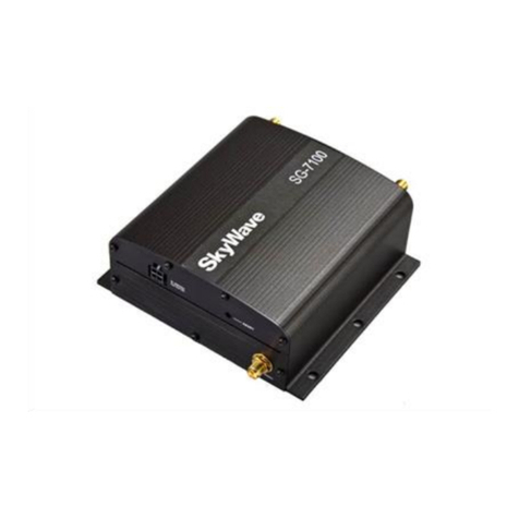
SkyWave IDP-782 Installation instructions

IDP-782
Hardware Guide
T213, Version .10
© SkyWave Mobile Communications Inc.
Nov 2014

IDP-782 - Hardware Guide
T213, Version .10 ii © SkyWave Proprietary
Legal Notice
This documentation is owned by SkyWave Mobile Communications Inc. (SkyWave) and protected by
applicable copyright laws and international treaty provisions. Other copyrighted names used are the property
of their respective owners. Therefore, you must treat this documentation like any other copyrighted material.
You may not make the documentation, or copies thereof, available in any manner or form, or use, copy or
transfer any part, to anyone outside your company.
If you received this documentation by electronic transmission or download, by installation or use of the
documentation, you acknowledge that you have read and understand this license agreement and agree to be
bound by its terms and conditions.
This documentation is provided on an as-is basis without any warranty of any kind. You assume the entire
risk as to the results or performance of the software. Under no circumstance shall SkyWave be held liable for
any direct, indirect, consequential, or incidental damages arising from the use or inability to use the software
or documentation.
All trademarks or registered trademarks are the property of their respective owners. INMARSAT, the
Inmarsat logo and IsatData Pro are trademarks of Inmarsat used under license by SkyWave. Inmarsat is not
responsible for the operation and regulatory compliance of the products and services referred to in this
document that connect to the Inmarsat system.
SkyWave reserves the right to make changes to products and or specifications without notice.
From support.skywave.com login, and follow the link to the downloads section.
Contact Information
SkyWave Mobile Communications Inc.
Online:
Website www.SkyWave.com
Online Documentation:
Login at support.skywave.com and follow the link to the downloads section
Customer Support by Email:
support@skywave.com
Customer Support by Telephone:
+1.613.836.2222
Documentation Feedback:
The Customer Documentation Department creates the SkyWave technical manuals.
Use the address below to tell us what you think about our technical documentation
and if you have suggestions for improvement.
In your feedback please reference a specific document number or title. We read all
feedback carefully, but please note that we cannot respond to the comments you
submit. If you require technical assistance, please contact SkyWave Customer
Support.
documentation@skywave.com

IDP-782 - Hardware Guide
© SkyWave Proprietary iii T213, Version .10
TABLE OF CONTENTS
Legal Notice....................................................................................................................................ii
Contact Information......................................................................................................................ii
List of Figures............................................................................................................................... vi
List of Tables................................................................................................................................ vii
Preface........................................................................................................................................... ix
Purpose ........................................................................................................................................ ix
Audience...................................................................................................................................... ix
Errata Sheet.................................................................................................................................. ix
Notation ....................................................................................................................................... ix
Reference..................................................................................................................................... ix
Safety Disclaimer.......................................................................................................................... x
Safety Precautions......................................................................................................................... x
Installation Warning ..................................................................................................................... x
Installer Responsibility................................................................................................................. x
Limited Liability.......................................................................................................................... xi
Warranty...................................................................................................................................... xi
User Serviceable Parts................................................................................................................ xii
1Product Overview ............................................................................................................... 1
1.1 Overview of the Messaging System................................................................................... 2
1.2 Terminal............................................................................................................................. 3
1.3 Terminal Key Features and Benefits.................................................................................. 4
1.4 Terminal Components........................................................................................................ 4
1.4.1 Transceiver Unit ............................................................................................................ 4
1.4.2 Cellular Antenna............................................................................................................ 6
1.4.3 IDP Standard Satellite Antenna..................................................................................... 7
1.4.3.1 Satellite Antenna Assembly ................................................................................................. 7
1.5 Pass-Through Mode ........................................................................................................... 8
2Compliance.......................................................................................................................... 9
3Specifications..................................................................................................................... 10
3.1 Temperature...................................................................................................................... 10
3.2 Electrical........................................................................................................................... 10
3.2.1 Input Range.................................................................................................................. 10
3.2.2 Power Consumption..................................................................................................... 11
3.2.2.1 Accelerometer Power Consumption....................................................................................12
3.2.3 Load Dump Protection................................................................................................. 12
3.2.4 Inrush Currents ............................................................................................................ 12
3.2.5 Cellular Antenna.......................................................................................................... 12
3.2.6 SIM Holders................................................................................................................. 13
3.3 Connectors........................................................................................................................ 13
3.4 Terminal Connector Layout ............................................................................................. 13
3.4.1 Connector Pin Assignment .......................................................................................... 14
3.4.2 Input/Output Interface Specifications.......................................................................... 15
3.4.2.1 Digital Input ........................................................................................................................15
3.4.2.2 Digital Output......................................................................................................................16

IDP-782 - Hardware Guide
T213, Version .10 iv © SkyWave Proprietary
3.4.2.3 Analog Input........................................................................................................................17
3.4.2.4 Open Drain Outputs ............................................................................................................18
3.4.2.5 Pass-Through Mode ............................................................................................................19
3.5 Serial Interfaces................................................................................................................ 19
3.5.1 CAN............................................................................................................................. 19
3.5.2 RS-485......................................................................................................................... 20
3.5.3 RS-232......................................................................................................................... 20
3.5.4 iButton Reader............................................................................................................. 21
3.5.5 USB.............................................................................................................................. 21
3.6 RF Specifications ............................................................................................................. 22
3.6.1 Standard Antenna......................................................................................................... 22
3.6.2 Low Elevation Antenna ............................................................................................... 22
3.7 GPS/GLONASS............................................................................................................... 22
3.8 Memory............................................................................................................................ 23
3.9 Environmental.................................................................................................................. 23
3.10 Sensors ............................................................................................................................. 24
3.10.1 Temperature Sensor..................................................................................................... 24
3.10.2 Accelerometer.............................................................................................................. 24
3.11 IDP-782 GPRS - Cellular Module.................................................................................... 25
3.12 IDP-782 HSPA - Cellular Module ................................................................................... 25
3.13 Mechanical....................................................................................................................... 26
3.13.1 Transceiver................................................................................................................... 26
3.13.2 Cellular Antenna.......................................................................................................... 26
3.13.3 Satellite Antenna.......................................................................................................... 27
3.13.3.1 Standard Antenna................................................................................................................27
3.13.3.2 Low Elevation Antenna.......................................................................................................28
4Installation......................................................................................................................... 29
4.1 Getting Started.................................................................................................................. 29
4.2 Prepare for the Installation............................................................................................... 29
4.2.1 Shipping Box Contents................................................................................................ 29
4.2.2 Additional Materials .................................................................................................... 29
4.2.3 Required Tools............................................................................................................. 30
4.2.4 Mobile Identification ................................................................................................... 30
4.2.5 Activate the Terminal .................................................................................................. 30
4.3 Determine a Suitable Mounting Location ........................................................................ 32
4.3.1 Standard Antenna Mounting Guidelines...................................................................... 33
4.3.2 Cellular Antenna Mounting Guidelines....................................................................... 33
4.4 Mount the Terminal.......................................................................................................... 34
4.4.1 Install the SIM Card..................................................................................................... 34
4.4.1.1 LED Location and Operation ..............................................................................................36
4.4.1.2 LED User Control ...............................................................................................................37
4.4.2 Determine Terminal Orientation for Accelerometer Use ............................................ 38
4.4.3 Drill Mounting Holes for the Transceiver Unit (optional)........................................... 38
4.5 Mount the Antennas ......................................................................................................... 39
4.5.1 Screw Mount................................................................................................................ 39
4.5.2 Adhesive Mount........................................................................................................... 40
4.5.2.1 Silicone Side Connector Mount ..........................................................................................41
4.5.2.2 Silicone Bottom Connector Mount......................................................................................42
4.5.3 Cellular Antenna.......................................................................................................... 45
4.6 Route the Main Cable....................................................................................................... 46
4.6.1 Protect the Cables and Cable Connectors.................................................................... 47

IDP-782 - Hardware Guide
© SkyWave Proprietary v T213, Version .10
4.7 Connect to Power ............................................................................................................. 47
4.7.1 CAN bus Connection................................................................................................... 48
4.8 Connect the Cables........................................................................................................... 48
4.8.1 Connect the Cables ...................................................................................................... 48
4.8.1.1 Disconnect the FAKRA Connector.....................................................................................50
4.9 Register the Terminal....................................................................................................... 50
4.10 Application Programming Interface................................................................................. 50
4.11 Cleaning Instructions........................................................................................................ 51
5Troubleshooting the Terminal......................................................................................... 52
5.1 Terminal Does Not Register or Report............................................................................. 52
APPENDIX A Order Part Numbers....................................................................................... 53
APPENDIX B Activation Information................................................................................... 54
APPENDIX C Satellite Antenna Dimensions ........................................................................ 55
APPENDIX D FAKRA Connector Antenna.......................................................................... 56
APPENDIX E Mating Cable Assembly Instructions ............................................................ 59
Mating Connector and Terminal Pins Part Numbers.................................................................. 59
Electrical Pin Assignments......................................................................................................... 59
Cable Selection........................................................................................................................... 59
Revision History .......................................................................................................................... 63
Acronyms/Glossary..................................................................................................................... 64
Index… ......................................................................................................................................... 65

IDP-782 - Hardware Guide
T213, Version .10 vi © SkyWave Proprietary
List of Figures
Figure 1 IDP-782.......................................................................................................................... 1
Figure 2 System Architecture....................................................................................................... 3
Figure 3 Transceiver..................................................................................................................... 5
Figure 4 Connector Positioning.................................................................................................... 5
Figure 5 Dual SIM Access Door.................................................................................................. 6
Figure 6 LEDs.............................................................................................................................. 6
Figure 7 Cellular Antenna............................................................................................................ 7
Figure 8 Standard Satellite Antenna............................................................................................. 7
Figure 9 Low Elevation Satellite Antenna................................................................................... 8
Figure 10 Transceiver View of Connector................................................................................. 14
Figure 11 Digital Input............................................................................................................... 15
Figure 12 Digital Output............................................................................................................ 16
Figure 13 Analog Input.............................................................................................................. 17
Figure 14 Open Drain Outputs................................................................................................... 18
Figure 15 Pass-Through Mode Signals...................................................................................... 19
Figure 16 Satellite Antenna (standard and low elevation) - Bottom View (mm)...................... 27
Figure 17 Low Elevation Antenna Height Dimensions (mm)................................................... 28
Figure 18 Mobile ID Location................................................................................................... 30
Figure 19 Manage Terminals..................................................................................................... 31
Figure 20 Sample Activation Report ......................................................................................... 31
Figure 21 Antenna Cable Bend Radius...................................................................................... 33
Figure 22 Remove SIM Card Door............................................................................................ 34
Figure 23 Remove an Existing SIM Card.................................................................................. 35
Figure 24 Sample SIM Card Orientation................................................................................... 35
Figure 25 SIM Card Installed .................................................................................................... 35
Figure 26 SIM Card Holders...................................................................................................... 35
Figure 27 LED Location............................................................................................................ 36
Figure 28 Power On Sequence................................................................................................... 36
Figure 29 Terminal Booting Sequence ...................................................................................... 36
Figure 30 Accelerometer and Terminal Orientation.................................................................. 38
Figure 31 Mounting Flange ....................................................................................................... 39
Figure 32 Air Vent Feature........................................................................................................ 40
Figure 33 Air Vent Feature........................................................................................................ 41
Figure 34 Apply Silicone to Antenna ........................................................................................ 42
Figure 35 Weight on the Antenna.............................................................................................. 42
Figure 36 Drill Mounting Hole.................................................................................................. 43
Figure 37 Attach Cable to Terminal .......................................................................................... 43
Figure 38 Apply Silicone to Hole in Asset................................................................................ 44
Figure 39 Apply Silicone to Terminal ....................................................................................... 45
Figure 40 Weight on the Antenna.............................................................................................. 45
Figure 41 Sample Cellular Mounting Locations –automobile example ................................... 46
Figure 42 Sample Cable Placement in a Vehicle Cab ............................................................... 46
Figure 43 Cable Management.................................................................................................... 47

IDP-782 - Hardware Guide
© SkyWave Proprietary vii T213, Version .10
Figure 44 Connect the Satellite Antenna ................................................................................... 49
Figure 45 Connect the Cellular Antenna ................................................................................... 49
Figure 46 Disconnecting the FAKRA Connector from the Transceiver Unit............................ 50
Figure 47 Disconnecting the FAKRA Connector from the Terminal........................................ 56
Figure 48 Locking Clip and Plastic Housing............................................................................. 56
Figure 49 Cable without Housing.............................................................................................. 57
Figure 50 Locking Clip (removed) and Plastic Housing ........................................................... 57
Figure 51 Connector Parts ......................................................................................................... 57
Figure 52 Strip the Cable........................................................................................................... 57
Figure 53 Insert Inner Conductor............................................................................................... 58
Figure 54 Insert Main Body....................................................................................................... 58
Figure 55 Slide Ferrule .............................................................................................................. 58
Figure 56 Main Body and Plastic Housing................................................................................ 58
Figure 57 Transceiver Electrical Mating Connector Pins (front view)...................................... 59
Figure 58 Mating Connector Electrical Cable (front view)....................................................... 59
Figure 59 Mating Cable............................................................................................................. 61
List of Tables
Table 1 Terminal Input Currents............................................................................................... 11
Table 2 Additional Terminal Input Currents............................................................................. 12
Table 3 Electrical Pin Assignment............................................................................................ 14
Table 4 Hardware GPS and Dual GPS/GLONASS Specifications .......................................... 22
Table 5 Modem State LED Flashing Patterns........................................................................... 37
Table 6 Order Part Numbers..................................................................................................... 53
Table 7 Connector and Crimp Contact Part Numbers .............................................................. 59
Table 8 Crimping and Extraction Tools.................................................................................... 61

IDP-782 - Hardware Guide
T213, Version .10 viii © SkyWave Proprietary
THIS PAGE INTENTIONALLY LEFT BLANK

IDP-782 - Hardware Guide
© SkyWave Proprietary ix T213, Version .10
Preface
Purpose
This document is as an overview of the installation procedures and hardware
characteristics and specifications for the IDP-782 satellite-cellular terminal.
Audience
This document is for technical readers. It provides information to ensure successful
installation and operation of IDP-782 satellite-cellular terminal.
Errata Sheet
Refer to the SkyWave Customer Support website for a possible Errata Sheet available
after the release of this document. Always check the site for the most current
documentation releases
Notation
The IDP-782 terminal is available in two models, IDP-782 GPRS (using GPRS) and IDP-
782 HSPA (using both HSPA and GPRS). With the exception of the different cellular
modules, all IDP-782 terminals offer the same features and functionality. Throughout this
document model names IDP-782 GPRS and IDP-782 HSPA will be used when
describing the cellular characteristics of the two models.
Hardware components and hardware labels in this document may not be exactly as shown
and are subject to change without notice.
CAUTION This safety symbol warns users of possible hazards to personnel,
to equipment, or to both. It includes hazards that can cause
severe personal injury, death, or substantial property damage if
the hazard is not avoided; and hazards that can cause minor
personal injury or property damage if the hazard is not avoided.
Note: A note indicates information with no potential hazard, but the user should
make special note. A note is also used to indicate points of interest or to provide
supplementary information about a feature or task.
Numbered lists indicate a series of steps required to complete a task or function.
Bulleted lists highlight information where order or sequence is not crucial.
Reference
The content of the following documents may be useful in conjunction with this guide.
These documents are available from support.skywave.com.
[N201] IsatData Pro Gateway Web Service User Guide
[N206] MTWS Cellular Protocol
[T202] IDP Terminal API Reference

IDP-782 - Hardware Guide
T213, Version .10 x © SkyWave Proprietary
[T203] IDP Modem Developer Guide
[T204] IDP Terminal User Guide
The following software tools are available from the IDP Toolkit or support.skywave.com.
Console
Safety Disclaimer
SkyWave makes no warranties, representations or guarantees that the products and
network services are suitable for any use in any hazardous environments requiring fail
safe performance (including without limitation marine safety and distress systems,
operation of nuclear facilities, aircraft navigation or communications systems, weapons
systems, air traffic control and life support services) or any other application in which the
failure of the products or network services could result in death or personal injury.
Solution Providers assume all liability associated with selling any products and network
services for any such applications, and Solution Provider will defend, indemnify, and
hold SkyWave harmless against any claims against SkyWave for loss, damage, liability,
or expense (including lawyers’ fees) arising out of or related to the sale by Solution
Providers or any Solution Provider Reseller, or the user by any end user, of any product
or network service.
Please read all cautions and warnings throughout this document.
Safety Precautions
The terminal must comply with all safety precautions relating to the operation, usage,
service and repair of the terminal. SkyWave assumes no liability for the customer’s
failure to comply with any of these precautions.
Caution warnings appear throughout this document.
Installation Warning
SkyWave recommends that this product be installed by the authorized distributor from
whom it has been purchased. By carrying out the installation of the product, the installer
assumes exclusive responsibility for, and agrees to indemnify SkyWave from, any injury
or damage of any kind arising from the installation.
Installer Responsibility
The installer is responsible for all injuries or damages arising out of or relating to any
wrongful or negligent act or omission of the installer (and/or any subcontractors) in
connection with the installation of any SkyWave product, except any such injuries or
damages arising solely from a defective SkyWave product. In addition to the liability
imposed upon the installer on the account of personal or property injury or damage,
bodily injury, including death, suffered as a result of the installer’s wrongful or negligent
installation of any SkyWave product, the installer assumes the obligation to defend,
indemnify and hold SkyWave harmless, including its directors, officers, employees,
agents and assigns, and to indemnify SkyWave, including its directors, officers,
employees, agents and assigns, from and against every damage, expense, liability or
payment arising out of or relating to such wrongful or negligent act or omission,

IDP-782 - Hardware Guide
© SkyWave Proprietary xi T213, Version .10
including legal and court fees. The installer also agrees to defend, indemnify and hold
SkyWave harmless, including its directors, officers, employees, agents and assigns, from
and against any wrongful or negligent act or omission committed by any subcontractor or
other person employed by or under the supervision of the installer for any purpose in
connection with the installation of SkyWave products, and to indemnify SkyWave,
including its directors, officers, employees, agents and assigns, from every damage,
expense, liability or payment arising out of or relating to such wrongful or negligent act
or omission, including legal and court fees. Every right, defence, and/or indemnity of
whatsoever nature applicable to SkyWave shall also be available and shall extend to
benefit and to protect the SkyWave’s directors, officers, employees, agents and assigns
and for such purposes SkyWave is or shall be deemed to be acting as agent or trustee on
behalf of and for the benefit of such companies and persons.
Limited Liability
SkyWave’s liability is limited to the cost of repair or replacement of any of SkyWave’s
products during the warranty period. To the maximum extent permitted by applicable
law, SkyWave's total liability for damages of any kind, whether based on breach of
contract, tort (including negligence), product liability, incidental, special, consequential,
indirect or similar damages with product application and usages will be limited to an
amount equal to the product's original price paid by the Purchaser to SkyWave and this
limitation of liability is reasonable given the price of SkyWave's products. In no event
will SkyWave be liable to the Purchaser, any resellers of the Purchaser or any end user
for any lost profits or savings, lost business, loss of data, any telecommunications
breakdown, unavailability, downtime, interruption or delay, any suspension of service by
any third party service provider including Inmarsat or any incidental, special, indirect, or
consequential damages, whether based on breach of contract, tort (including negligence),
product liability, incidental, special, consequential, indirect or similar damages and
whether or not SkyWave has been advised of the possibility of such occurrence or
damage. The parties agree that the foregoing represents a fair allocation of risk
hereunder.
Warranty
SkyWave provides a manufacturer’s warranty to the original purchaser (Solution
Provider) that its products and services will perform in accordance with SkyWave’s
specifications and will be free from defects in material and workmanship for a limited
period of time. This warranty is limited to the repair and/or replacement of any defective
components experienced under normal specified operating use and storage conditions, at
SkyWave’s discretion. Please check your Solution Provider agreement for warranty
details and conditions. It does not cover any damages caused or associated with the
product’s misuse. The end-user’s only remedy or recourse is against the Solution
Provider, and any experience with defective products should be communicated to your
Solution Provider. Shipping of defective product, back to the Solution Provider will be in
accordance with the Solution Provider’s instructions and should be accompanied with a
fault report. SkyWave is not responsible for corrosion damage caused by improperly
assembled or installed cables. Warranty is void if unit is opened.
A fault report is required for each unit returned under warranty. Please contact
SkyWave’s Customer Support for additional information.

IDP-782 - Hardware Guide
T213, Version .10 xii © SkyWave Proprietary
User Serviceable Parts
The IDP-782 contains two SIM card holders and may also have SIM cards installed (not
supplied by SkyWave).

IDP-782 - Hardware Guide
© SkyWave Proprietary 1 T213, Version .10
1 Product Overview
The IDP-782 (Figure 1) is a high-performance satellite-cellular communication terminal
consisting of:
A transceiver unit
An IsatData Pro satellite modem for communicating with the satellite
An integral GPS/GLONASS subsystem
I/O interface for wired sensors and devices
Two RS-232 ports
RS-485 port
CAN bus port
iButton interface
Mini-B USB Slot
Two SIM card slots
Cellular module (GPRS or HSPA)
Satellite antenna
Cellular antenna
Figure 1 IDP-782
The terminal’s built-in programmability allows it to work as a stand-alone data-
messaging terminal, with built-in I/O data collection and processing capabilities. Feature-
rich software tools make programming easy and shorten the design and testing time.

IDP-782 - Hardware Guide
T213, Version .10 2 © SkyWave Proprietary
1.1 Overview of the Messaging System
SkyWave's IsatData Pro satellite messaging system is designed to support the
management of mobile or fixed assets located around the world. An asset fitted with one
of SkyWave's satellite based mobile terminals can have their status and locations
monitored, as well as send large messages.
The network provides the following key features and benefits:
Polling of terminal status and location
Scheduled reporting of terminal status and location
Transmission of text messages to and from a serial port on the terminal
Two-way communication for messaging to and from the asset for near real-time
control
Up to 6,400 bytes from-mobile messages
Up to 10,000 bytes to-mobile messages
Default acknowledged messages
Global service
Service is provided to end users by Solution Providers (SPs) who use the SkyWave
IsatData Pro network to offer particular applications and/or services to their clients. The
SPs link their application services to the satellite terminals by connecting to the IsatData
Pro gateway. This acts as the communications hub of the system, routing traffic to and
from the terminals and the various service providers.
The IDP-782 terminal can be configured to route cellular messages through the same
SkyWave IsatData Pro Gateway that supplies satellite messages. This is shown as Option
1 in the System Diagram. Option 2 represents a terminal configured to route cellular
messages directly to a customer or Solution Provider proprietary cell server. In this case
the connection to SkyWave’s IsatData Pro Gateway only supplies satellite messages.
Refer to [T202, N201, and N206] for more information about configuring the terminal’s
cellular messaging transport.

IDP-782 - Hardware Guide
© SkyWave Proprietary 3 T213, Version .10
Figure 2 System Architecture
The satellite-cellular terminals are based on the IDP-680/IDP-690 Lua software and are
supported by the same suite of IDP tools, enabling SPs a programmable platform they
can tailor to their specific applications.
1.2 Terminal
1
Terminals with a standard antenna operate on the IsatData Pro network at an elevation
angle of 20° to 90° and -15° to 90° for terminals with low elevation antennas. The
terminals are self-contained, compact, and provide low power consumption.
The terminal's built-in programmability allows it to work as a stand-alone terminal with
built-in I/O data collection and processing capabilities. Terminals are suitable for the
AVL market.
Feature-rich software tools make application design easy, and shorten the design and
testing time. SkyWave also provides consulting services to SPs to help program the
terminals and get customer applications running quickly.
The terminals include an IsatData Pro satellite modem, a cellular modem with two SIM
card slots, and programmable microprocessor and file system for firmware and
peripherals. Peripherals include CAN bus for vehicle bus access, several I/O
(input/output) feeds, RS-485, and two RS-232 ports.
1
Hardware components may not be exactly as shown in this document. A terminal consists of a
transceiver unit plus antennas. Part numbers are specified in Table 6.

IDP-782 - Hardware Guide
T213, Version .10 4 © SkyWave Proprietary
1.3 Terminal Key Features and Benefits
CAUTION Do not rely solely on the terminal for emergency (SOS) calls.
The terminal has the following key features and benefits:
Designed to be used as a standalone or incorporated into an SP solution
Built-in GPS or dual GPS/GLONASS receiver to calculate position, speed and
heading
Quick and easy installation reduces labor time and costs
Ships with installed firmware
Flexible custom application design (Lua Services Framework)
Wide operational temperature range
Satellite plus cellular modem integration
Discrete I/O ports to interface with a wide range of after-market accessories
Rugged construction
Dual SIM
1.4 Terminal Components
Each terminal consists of the following components, excluding interconnecting cabling.
Transceiver unit
Cellular antenna
IsatData Pro satellite antenna
1.4.1 Transceiver Unit
Each transceiver is a self-contained unit, including satellite transceiver (modem), quad-
band cellular modem, GPS or dual GPS/GLONASS module, programmable
microcontroller, and multiple I/O (input/output) feeds capable of monitoring and
controlling external sensors and devices. Ideal for mobile applications, it is also suitable
for fixed installations. Refer to APPENDIX A for details.
The transceiver unit (Figure 3) is not waterproof. Use it in an indoor environment, e.g.,
inside a vehicle, away from environmental exposure (i.e., any form of moisture such as
rain, snow, or pooled water). The transceiver is a side connector mounting unit.

IDP-782 - Hardware Guide
© SkyWave Proprietary 5 T213, Version .10
Figure 3 Transceiver
Arranging the transceiver unit’s connectors (Figure 4) at one end of the unit makes
installation easier. Sturdy flanges on the side make mounting quick and easy.
Figure 4 Connector Positioning
An anti-tamper SIN door on the side of the unit (Figure 5) provides easy access to the
two SIM card holders for installation and replacement. A mini-B connector located next
to the SIM door provides a USB connection to the terminal.
Satellite FAKRA Connector
(curry yellow)
Cellular FAKRA Connector (violet)
30-Pin Connector

IDP-782 - Hardware Guide
T213, Version .10 6 © SkyWave Proprietary
Figure 5 Dual SIM Access Door
Figure 6 LEDs
1.4.2 Cellular Antenna
Terminals use a standard low-profile cellular antenna. The cellular antenna is a quad-
band adhesive patch antenna, designed for installation on the interior of a vehicle
windshield. It connects to the transceiver unit with a 2.5 m cable terminated with a
FAKRA connector.
Optional screw for anti-
tamper
Mini-B USB Slot
Satellite Antenna
Connector
Cellular Antenna
Connector
Power Status
Satellite
Status
Cellular
Status
Power and I/O
Connector
SIM Door

IDP-782 - Hardware Guide
© SkyWave Proprietary 7 T213, Version .10
Figure 7 Cellular Antenna
1.4.3 IDP Standard Satellite Antenna
The IsatData Pro satellite antenna is waterproof (IP67 rated) and designed to operate in
extreme environments. It has four mounting flanges for installation.
Each satellite antenna connects to the transceiver unit using a cable terminated with a
curry yellow colored FAKRA RF connector.
CAUTION Observe proper ESD handling procedures when handling the
antenna cable connector.
1.4.3.1 Satellite Antenna Assembly
The satellite antenna assembly is an active antenna –it uses a DC voltage on the cable.
The DC voltage powers an LNA for the satellite receiver and a power amplifier for the
satellite transmitter.
The antenna assembly consists of a single RoHS compliant PCB, and assembly
containing no user serviceable parts. The antenna assembly consists of a single RoHS
compliant PCB protected by an IP67 rated waterproof enclosure.
The IDP-782 is available with either the standard satellite antenna (Figure 8) or the low
elevation satellite antenna (Figure 9).
Figure 8 Standard Satellite Antenna

IDP-782 - Hardware Guide
T213, Version .10 8 © SkyWave Proprietary
Figure 9 Low Elevation Satellite Antenna
1.5 Pass-Through Mode
The terminal operates in pass-through mode when there is no valid application firmware
present. In pass-through mode, the terminal connects the external RS-232 port to the
serial port on its internal modem, making the terminal an IP67 modem that accepts a wide
input voltage. The packaged modem inherits all of the terminal certifications.
Other manuals for IDP-782
1
Table of contents
Other SkyWave Conference System manuals
