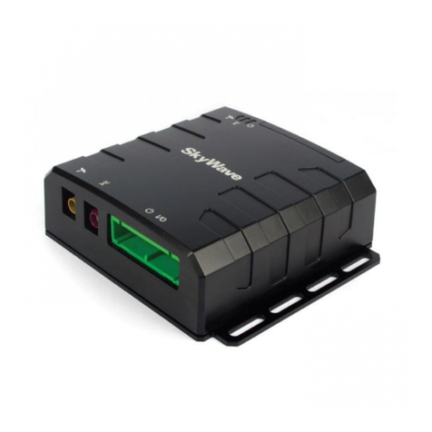
SkyWave SG-7100 Installation instructions

SG-7100
Hardware Guide
T300, Version 01
The electronic version of this document allows
you to use the built-in Hyperlinks and
bookmarks when using Adobe Reader
© SkyWave Mobile Communications Inc.
Nov 2014

SG-7100 - Hardware Guide
T300, Version 01 ii © SkyWave Proprietary
Legal Notice
This documentation is owned by SkyWave Mobile Communications Inc. (SkyWave) and protected by
applicable copyright laws and international treaty provisions. Other copyrighted names used are the property
of their respective owners. Therefore, you must treat this documentation like any other copyrighted material.
You may not make the documentation, or copies thereof, available in any manner or form, or use, copy or
transfer any part, to anyone outside your company.
If you received this documentation by electronic transmission or download, by installation or use of the
documentation, you acknowledge that you have read and understand this license agreement and agree to be
bound by its terms and conditions.
This documentation is provided on an as-is basis without any warranty of any kind. You assume the entire
risk as to the results or performance of the software. Under no circumstance shall SkyWave be held liable for
any direct, indirect, consequential, or incidental damages arising from the use or inability to use the software
or documentation.
All trademarks or registered trademarks are the property of their respective owners. INMARSAT, the
Inmarsat logo and IsatData Pro are trademarks of Inmarsat used under license by SkyWave. Inmarsat is not
responsible for the operation and regulatory compliance of the products and services referred to in this
document that connect to the Inmarsat system. Wi-Fi is a registered trademark of Wi-Fi Alliance. 1-Wire is a
registered trademark of Maxim Integrated™ Products Inc. Micro-Fit 3.0 is a Molex trademark. gpsOneXTRA
Assistance is a trademark of Qualcomm Incorporated. Loctite and Threadlocker Blue 242 are registered
trademarks of Henkel.
Option NV materials are reproduced with permission of the copyright owner.
SkyWave reserves the right to make changes to products and or specifications without notice.
Contact Information
SkyWave Mobile Communications Inc.
Online:
Website www.SkyWave.com
Online Documentation:
Login at support.skywave.com and follow the link to the downloads section
Customer Support by Email:
support@skywave.com
Customer Support by Telephone:
+1.613.836.2222
Documentation Feedback:
The Customer Documentation Department creates the SkyWave technical manuals.
Use the address below to tell us what you think about our technical documentation
and if you have suggestions for improvement.
In your feedback please reference a specific document number or title. We read all
feedback carefully, but please note that we cannot respond to the comments you
submit. If you require technical assistance, please contact SkyWave Customer
Support.
documentation@skywave.com

SG-7100 - Hardware Guide
© SkyWave Proprietary iii T300, Version 01
TABLE OF CONTENTS
Legal Notice....................................................................................................................................ii
Contact Information......................................................................................................................ii
List of Figures............................................................................................................................... vi
List of Tables................................................................................................................................ vii
Preface........................................................................................................................................... ix
Purpose ........................................................................................................................................ ix
Audience...................................................................................................................................... ix
Errata Sheet.................................................................................................................................. ix
Notation ....................................................................................................................................... ix
Reference..................................................................................................................................... ix
Safety Disclaimer.......................................................................................................................... x
Safety Precautions......................................................................................................................... x
Installation Warning ..................................................................................................................... x
Installer Responsibility................................................................................................................. x
Limited Liability.......................................................................................................................... xi
Warranty...................................................................................................................................... xi
1Product Overview ............................................................................................................... 1
1.1 Key Features and Benefits.................................................................................................. 1
1.2 SG-7100 Components ........................................................................................................ 2
1.2.1 Base Unit....................................................................................................................... 2
1.2.1.1 Front Panel ........................................................................................................................... 3
1.2.1.2 Back Panel............................................................................................................................ 3
1.2.2 Expansion Cards............................................................................................................ 4
1.2.2.1 WLAN/Wi-Fi Expansion Card............................................................................................. 4
1.2.2.2 Simplex Serial Expansion Card............................................................................................ 4
1.2.2.3 Industrial Expansion Card.................................................................................................... 5
1.2.2.4 Telematics Expansion Card.................................................................................................. 5
1.2.3 Antennas........................................................................................................................ 5
1.2.3.1 Cellular Antenna .................................................................................................................. 5
1.2.3.2 Cellular plus GPS Antenna................................................................................................... 6
1.2.3.3 WLAN (Wi-Fi) Antenna Fixed............................................................................................ 6
1.2.3.4 WLAN (Wi-Fi) Antenna Hinged ......................................................................................... 6
1.2.4 Software Bundles.......................................................................................................... 7
2Specifications....................................................................................................................... 8
2.1 Temperature........................................................................................................................ 8
2.2 Electrical............................................................................................................................. 8
2.2.1 Power Supply................................................................................................................ 8
2.2.1.1 Load Dump Protection ......................................................................................................... 8
2.2.1.2 Base Unit Internal Power Supply ......................................................................................... 8
2.2.2 SIM Card Holders......................................................................................................... 9
2.2.3 Power Consumption...................................................................................................... 9
2.2.3.1 Accelerometer Power Consumption..................................................................................... 9
2.3 Processor and Operating System...................................................................................... 10
2.4 Memory............................................................................................................................ 10
2.5 Environmental.................................................................................................................. 10

SG-7100 - Hardware Guide
T300, Version 01 iv © SkyWave Proprietary
2.6 Physical Details................................................................................................................ 11
2.7 Ethernet Interface............................................................................................................. 12
2.8 Status Indicators............................................................................................................... 12
2.9 WWAN (Cellular) Interface............................................................................................. 14
2.10 GPS................................................................................................................................... 14
2.11 Satellite (optional)............................................................................................................ 14
2.12 Antennas........................................................................................................................... 15
2.12.1 Cellular Antenna ......................................................................................................... 15
2.12.2 Cellular plus GPS Antenna ......................................................................................... 15
2.12.3 WLAN (Wi-Fi) Antenna............................................................................................. 16
2.13 Expansion Cards - Serial Interfaces ................................................................................. 17
2.13.1 WLAN/Wi-Fi Expansion Card.................................................................................... 17
2.13.2 Simplex Serial Expansion Card................................................................................... 18
2.13.3 Industrial Serial Card .................................................................................................. 19
2.13.4 Telematics Card .......................................................................................................... 21
2.13.4.1 RS-232 ................................................................................................................................22
2.13.4.2 Input/Output ........................................................................................................................23
2.13.4.3 Default Jumpers Configuration ...........................................................................................25
2.13.4.4 RS-485 Jumper Configuration.............................................................................................26
2.13.4.5 Connectors...........................................................................................................................26
2.14 Accelerometer Sensors..................................................................................................... 26
2.14.1.1 Accelerometer Operating Modes.........................................................................................27
2.14.1.2 Sampling Rates....................................................................................................................28
3Installation......................................................................................................................... 29
3.1 Getting Started.................................................................................................................. 29
3.2 Prepare for the Installation ............................................................................................... 29
3.2.1 Tools Required............................................................................................................ 29
3.2.2 Shipping Box Contents ............................................................................................... 29
3.2.3 Mobile ID.................................................................................................................... 30
3.3 Install the SIM Card (optional) ........................................................................................ 30
3.3.1 Insert a Single SIM Card............................................................................................. 31
3.3.2 Insert Multiple SIM Cards .......................................................................................... 32
3.4 Install Expansion Cards (optional)................................................................................... 33
3.5 Attach the Antennas ......................................................................................................... 33
3.6 Determine a Suitable Mounting Location ........................................................................ 34
3.7 Mount the SG-7100.......................................................................................................... 35
3.7.1 Required Materials...................................................................................................... 35
3.7.2 Determine Terminal Orientation for Accelerometer Use............................................ 35
3.7.3 Mount the Unit............................................................................................................ 35
3.8 Connect an IDP Terminal (optional)................................................................................ 36
3.9 Connect to Power ............................................................................................................. 36
3.10 Route the Main Cable....................................................................................................... 36
3.11 Protect the Cables and Power Connector ......................................................................... 37
3.12 Configure and Register the SG-7100 ............................................................................... 37
4Compliance........................................................................................................................ 38
APPENDIX A Orderable Part Numbers ............................................................................... 39
APPENDIX B IDP Power and Serial Cable Pin-out............................................................. 40
Revision History .......................................................................................................................... 41

SG-7100 - Hardware Guide
© SkyWave Proprietary v T300, Version 01
Acronyms/Glossary..................................................................................................................... 42
Index… ......................................................................................................................................... 43

SG-7100 - Hardware Guide
T300, Version 01 vi © SkyWave Proprietary
List of Figures
Figure 1 SG-7100 ........................................................................................................................ 1
Figure 2 SG-7100 Base Unit ....................................................................................................... 2
Figure 3 SG-7100 Front Panel..................................................................................................... 3
Figure 4 SG-7100 Back Panel..................................................................................................... 4
Figure 5 WLAN/Wi-Fi Expansion Card...................................................................................... 4
Figure 6 Simplex Serial Expansion Card..................................................................................... 4
Figure 7 Industrial Expansion Card............................................................................................. 5
Figure 8 Telematics Expansion Card........................................................................................... 5
Figure 9 Cellular Antenna ........................................................................................................... 5
Figure 10 Cellular/GPS Antenna ................................................................................................. 6
Figure 11 WLAN (Wi-Fi) Antenna - Fixed................................................................................. 6
Figure 12 WLAN (Wi-Fi) Antenna - Hinged .............................................................................. 6
Figure 13 SG-7100 Side View Dimensions (mm)..................................................................... 11
Figure 14 SG-7100 Top View Dimensions (mm)...................................................................... 11
Figure 15 Ethernet Pin-out......................................................................................................... 12
Figure 16 LEDs.......................................................................................................................... 12
Figure 17 Sample SSID Label ................................................................................................... 17
Figure 18 Simplex Serial Expansion Card................................................................................. 18
Figure 19 Simplex Serial Expansion Card RS-232 Serial Connector (female) ......................... 18
Figure 20 SG-7100 Connected with a DTE Device................................................................... 19
Figure 21 SG-7100 Connected with a DCE Device .................................................................. 19
Figure 22 Industrial Expansion Card......................................................................................... 19
Figure 23 Industrial Serial Card RS-232 Serial Connector Pin-out (female) ............................ 20
Figure 24 Telematics Card......................................................................................................... 21
Figure 25 RS-232 Connector (male).......................................................................................... 22
Figure 26 Telematics Pin Outs................................................................................................... 23
Figure 27 Jumpers...................................................................................................................... 25
Figure 28 Sample Mobile ID ..................................................................................................... 30
Figure 29 Remove Panel............................................................................................................ 31
Figure 30 Remove the SIM Card............................................................................................... 31
Figure 31 Insert SIM Card......................................................................................................... 32
Figure 32 Telematics Card SIM Card Holder Location............................................................. 32
Figure 33 Attach Antennas ........................................................................................................ 34
Figure 34 Accelerometer and Terminal Orientation.................................................................. 35
Figure 35 Power Connector....................................................................................................... 36
Figure 36 Cable Management.................................................................................................... 37
Figure 37 IDP Power and Serial Cable...................................................................................... 40

SG-7100 - Hardware Guide
© SkyWave Proprietary vii T300, Version 01
List of Tables
Table 1 Temperature Ratings..................................................................................................... 8
Table 2 Power Connector Pin-out (facing view of cable connector) ......................................... 8
Table 3 Accelerometer Power Consumption Factors................................................................. 9
Table 4 Supported Sleep Phase Durations. .............................................................................. 10
Table 5 SG-7100 Mass and Materials...................................................................................... 12
Table 6 LED Descriptions........................................................................................................ 13
Table 7 Ethernet LEDs............................................................................................................. 14
Table 8 Pin-out of Serial Connector......................................................................................... 18
Table 9 Pin-out of Serial Connector......................................................................................... 20
Table 10 RS-485 Pin-outs.......................................................................................................... 20
Table 11 Pin-out of RS-232 Serial Connector (male)................................................................ 22
Table 12 Default (RS-232) I/O Connector Pin-outs................................................................... 23
Table 13 RS-485 I/O Connector Pin-outs.................................................................................. 23
Table 14 Digital Inputs (Input1 to Input5)................................................................................. 24
Table 15 Optional Analog Inputs (Input1 to Input5) ................................................................. 24
Table 16 Analog Inputs (Input6 and Input7).............................................................................. 24
Table 17 Digital Outputs (Output8, Output9, Output13 and Output14) .................................... 25
Table 18 Default/Factory Jumper Settings*............................................................................... 25
Table 19 RS-485 Jumper Settings*............................................................................................ 26
Table 20 Accelerometer Power Modes...................................................................................... 27
Table 21 Sample Rates............................................................................................................... 28
Table 22 Orderable Part Numbers.............................................................................................. 39
Table 23 Wiring Chart................................................................................................................ 40

SG-7100 - Hardware Guide
T300, Version 01 viii © SkyWave Proprietary
THIS PAGE INTENTIONALLY LEFT BLANK

SG-7100 - Hardware Guide
© SkyWave Proprietary ix T300, Version 01
Preface
Purpose
This document provides an overview of the installation procedures as well as hardware
characteristics and specifications for the SG-7100.
Audience
This document is for Solution Providers, system Integrators and Field Engineers. It
provides information to ensure successful installation and operation of the SG-7100.
Errata Sheet
Refer to the SkyWave Customer Support website for a possible Errata Sheet available
after the release of this document. Always check the site for the most current
documentation releases.
Notation
Hardware components and hardware labels in this document may not be exactly as shown
and are subject to change without notice.
CAUTION This safety symbol warns users of possible hazards to personnel,
to equipment, or to both. It includes hazards that will or can
cause severe personal injury, death, or substantial property
damage if the hazard is not avoided; and hazards that will or can
cause minor personal injury or property damage if the hazard is
not avoided.
Note: A note indicates information with no potential hazard, but the user should
make special note. A note is also used to indicate points of interest or to provide
supplementary information about a feature or task.
Numbered lists indicate a series of steps required to complete a task or function.
Bulleted lists highlight information where order or sequence is not crucial.
Reference
The content of the following documents may be useful in conjunction with this guide.
These documents are available from the IDP Toolkit or support.skywave.com.
[T200] IDP-680 Hardware Guide
[T212] IDP-280 Hardware Guide
[T301] SG-7100 API Reference
[T302] SG-7100 User Guide

SG-7100 - Hardware Guide
T300, Version 01 x © SkyWave Proprietary
Safety Disclaimer
SkyWave makes no warranties, representations or guarantees that the products and
network services are suitable for any use in any hazardous environments requiring fail
safe performance (including without limitation marine safety and distress systems,
operation of nuclear facilities, aircraft navigation or communications systems, weapons
systems, air traffic control and life support services) or any other application in which the
failure of the products or network services could result in death or personal injury.
Solution Providers assume all liability associated with selling any products and network
services for any such applications, and Solution Provider will defend, indemnify, and
hold SkyWave harmless against any claims against SkyWave for loss, damage, liability,
or expense (including lawyers' fees) arising out of or related to the sale by Solution
Providers or any Solution Provider Reseller, or the user by any end user, of any product
or network service.
Please read all cautions and warnings throughout this document.
Safety Precautions
The terminal must comply with all safety precautions relating to the operation, usage,
service and repair of the terminal. SkyWave assumes no liability for the customer's
failure to comply with any of these precautions.
Caution warnings appear throughout this document.
Installation Warning
SkyWave recommends that this product be installed by the authorized distributor from
whom it has been purchased. By carrying out the installation of the product, the installer
assumes exclusive responsibility for, and agrees to indemnify SkyWave from, any injury
or damage of any kind arising from the installation.
Installer Responsibility
The installer is responsible for all injuries or damages arising out of or relating to any
wrongful or negligent act or omission of the installer (and/or any subcontractors) in
connection with the installation of any SkyWave product, except any such injuries or
damages arising solely from a defective SkyWave product. In addition to the liability
imposed upon the installer on the account of personal or property injury or damage,
bodily injury, including death, suffered as a result of the installer's wrongful or negligent
installation of any SkyWave product, the installer assumes the obligation to defend,
indemnify and hold SkyWave harmless, including its directors, officers, employees,
agents and assigns, and to indemnify SkyWave, including its directors, officers,
employees, agents and assigns, from and against every damage, expense, liability or
payment arising out of or relating to such wrongful or negligent act or omission,
including legal and court fees. The installer also agrees to defend, indemnify and hold
SkyWave harmless, including its directors, officers, employees, agents and assigns, from
and against any wrongful or negligent act or omission committed by any subcontractor or
other person employed by or under the supervision of the installer for any purpose in
connection with the installation of SkyWave products, and to indemnify SkyWave,
including its directors, officers, employees, agents and assigns, from every damage,

SG-7100 - Hardware Guide
© SkyWave Proprietary xi T300, Version 01
expense, liability or payment arising out of or relating to such wrongful or negligent act
or omission, including legal and court fees. Every right, defence, and/or indemnity of
whatsoever nature applicable to SkyWave shall also be available and shall extend to
benefit and to protect the SkyWave's directors, officers, employees, agents and assigns
and for such purposes SkyWave is or shall be deemed to be acting as agent or trustee on
behalf of and for the benefit of such companies and persons.
Limited Liability
SkyWave's liability is limited to the cost of repair or replacement of any of SkyWave's
products during the warranty period. To the maximum extent permitted by applicable
law, SkyWave's total liability for damages of any kind, whether based on breach of
contract, tort (including negligence), product liability, incidental, special, consequential,
indirect or similar damages with product application and usages will be limited to an
amount equal to the product's original price paid by the Purchaser to SkyWave and this
limitation of liability is reasonable given the price of SkyWave's products. In no event
will SkyWave be liable to the Purchaser, any resellers of the Purchaser or any end user
for any lost profits or savings, lost business, loss of data, any telecommunications
breakdown, unavailability, downtime, interruption or delay, any suspension of service by
any third party service provider including Inmarsat or any incidental, special, indirect, or
consequential damages, whether based on breach of contract, tort (including negligence),
product liability, incidental, special, consequential, indirect or similar damages and
whether or not SkyWave has been advised of the possibility of such occurrence or
damage. The parties agree that the foregoing represents a fair allocation of risk
hereunder.
Warranty
SkyWave provides a manufacturer's warranty to the original purchaser (Solution
Provider) that its products and services will perform in accordance with SkyWave's
specifications and will be free from defects in material and workmanship for a limited
period of time. This warranty is limited to the repair and/or replacement of any defective
components experienced under normal specified operating use and storage conditions, at
SkyWave's discretion. Please check your Solution Provider agreement for warranty
details and conditions. It does not cover any damages caused or associated with the
product's misuse. The end-user's only remedy or recourse is against the Solution
Provider, and any experience with defective products should be communicated to your
Solution Provider. Shipping of defective product, back to the Solution Provider will be in
accordance with the Solution Provider's instructions and should be accompanied with a
fault report. SkyWave is not responsible for corrosion damage caused by improperly
assembled or installed cables.
A fault report is required for each unit returned under warranty. Please contact
SkyWave's Customer Support for additional information.

SG-7100 - Hardware Guide
T300, Version 01 xii © SkyWave Proprietary
THIS PAGE INTENTIONALLY LEFT BLANK

SG-7100 - Hardware Guide
© SkyWave Proprietary 1 T300, Version 01
1 Product Overview
The SG-7100 (Figure 1) is a Linux-based cellular communications platform with optional
Wi-Fi®and satellite, providing uninterrupted connectivity for integration into fleet
management and industrial fixed asset monitoring applications.
Figure 1 SG-7100
The fully programmable SG-7100 allows you to create your own applications through the
use of Lua and open Linux development environments, and supports multiple LAN and
WAN interfaces along with providing an onboard web server.
The modular hardware architecture and optional expansion cards offer the flexibility to
meet evolving asset management challenges by allowing connection to a wide range of
field peripherals and instruments using serial, Ethernet, 1-Wire®, digital and analog ports.
1.1 Key Features and Benefits
The SG-7100 is a high-performance cellular communications device intended for either
mobile or fixed applications and includes the following feature set:
Linux-based remote gateway with 3G cellular and Ethernet
Cellular
GSM –Quad-band GPRS/EDGE, Penta-band HSPA/HSPA+
CDMA –1xRTT, EV-DO
Programmability –Lua Services Framework, SkyWave M2M agents, Web server for
smart devices, and native Linux applications.
Optional IsatData Pro satellite communications
Expansion card architecture
WLAN/Wi-Fi Expansion Card
Simplex Serial Expansion Card
RS-232

SG-7100 - Hardware Guide
T300, Version 01 2 © SkyWave Proprietary
Industrial Serial Card
RS-485
RS-232
Telematics Card
Accelerometer
CAN bus/J1939
Input/outputs
RS-232/RS-485 or 2 x RS-232
USB (OTG and Host)
1-Wire
Dual SIM slots
1.2 SG-7100 Components
Each SG-7100 consists of the following components, excluding interconnecting cabling:
Base Unit
Expansion Cards (optional)
Antennas (optional)
Software Bundles
1.2.1 Base Unit
The base unit (Figure 2) includes an internal main board with WWAN module, Ethernet
interface and GPS. It also supports two hardware expansion slots for additional radio or
wired interfaces. The base unit is available in two versions: Americas and EMEA with
the difference being in the installed cellular firmware and certifications.
Figure 2 SG-7100 Base Unit

SG-7100 - Hardware Guide
© SkyWave Proprietary 3 T300, Version 01
Also provided are LAN-to-WWAN and GPS interfaces and advanced error detection and
repair watchdogs. When a component or software process loses connectivity, the device
automatically resets or repowers itself. You can also schedule the device to reset at
specific intervals ([T302]).
The SG-7100 can be monitored and provisioned remotely, which reduces the technician
time on site, and enables firmware updates and new software features to be deployed
quickly and efficiently.
1.2.1.1 Front Panel
The front panel (Figure 3) provides access to the following:
1. WWAN (cellular) diversity/GPS antenna connector (SMA-female) (Section
2.12.2)
2. LEDs (Section 2.8) including WLAN, GPS, System, and WWAN LEDs showing
system status and signal strength
3. Ethernet port (Section 2.7)
4. WWAN Main (cellular) antenna connector (Section 2.12.1)
Figure 3 SG-7100 Front Panel
1.2.1.2 Back Panel
The back panel (Figure 4) provides access to the following:
1. Power connector (Section 2.1)
2. Reset button
Use a small screwdriver or pen to press and hold the reset button for less than 5
seconds to reset the SG-7100 to the last working setting (normal reset). Press and
hold for 5 seconds or more to reset the SG-7100 to factory settings.
The unit can also be reset using the web interface [T302].
3. WLAN (Wi-Fi) main connector (Section 2.12.3)
Available on the optional WLAN/Wi-Fi expansion card.
1
2
3
4

SG-7100 - Hardware Guide
T300, Version 01 4 © SkyWave Proprietary
Figure 4 SG-7100 Back Panel
1.2.2 Expansion Cards
Several expansion cards are available to expand the capabilities of the SG-7100. A total
of two optional expansion cards can be installed. Expansion cards are built specifically
for the front and back panels and they are not interchangeable.
1.2.2.1 WLAN/Wi-Fi Expansion Card
The WLAN/Wi-Fi expansion card (ST100303-001), accessible from the back panel,
provides service or connection as a wireless LAN. This card includes an antenna
connector which accepts a reverse polarity SMA male antenna (Figure 5).
Figure 5 WLAN/Wi-Fi Expansion Card
1.2.2.2 Simplex Serial Expansion Card
This card (Figure 6) provides an RS-232 port and is accessible from the front panel. This
card is identical to the industrial expansion card (Figure 7) except that it does not have an
RS-485 port.
Figure 6 Simplex Serial Expansion Card
1
2
3

SG-7100 - Hardware Guide
© SkyWave Proprietary 5 T300, Version 01
1.2.2.3 Industrial Expansion Card
This card (Figure 7) is accessible from the front panel and provides RS-232 and RS-485
capabilities.
Figure 7 Industrial Expansion Card
1.2.2.4 Telematics Expansion Card
The Telematics (Figure 8) expansion card (OEM100044) is accessible from the front
panel.
Figure 8 Telematics Expansion Card
1.2.3 Antennas
Three antenna types are available separately for use with the SG-7100: cellular, cellular
plus GPS and WLAN (Wi-Fi). The WLAN (Wi-Fi) antenna is available in two models, a
fixed 2.4 GHz only version and a hinged 2.4 GHz and 5.8 GHz version.
1.2.3.1 Cellular Antenna
The Cellular antenna (ST100304-001) (Figure 9) is a Penta-band 3G cellular antenna. It
supports all of the cellular bands used by the SG-7100. This antenna is connected to the
SG-7100 antenna connector labeled, "WWAN Main" on the base unit.
Figure 9 Cellular Antenna

SG-7100 - Hardware Guide
T300, Version 01 6 © SkyWave Proprietary
1.2.3.2 Cellular plus GPS Antenna
The Cellular/GPS antenna (ST100304-002) (Figure 10) offers similar functionality to the
main cellular antenna; in addition it supports GPS signals. The cellular plus GPS antenna
is mainly used for GPS, but it also provides cellular diversity, which improves the
reliability of cellular reception. This antenna is connected to the SG-7100 antenna
connector labeled, "WWAN Div/GPS" on the base unit.
Figure 10 Cellular/GPS Antenna
1.2.3.3 WLAN (Wi-Fi) Antenna Fixed
The WLAN/Wi-Fi fixed antenna (ST100304-004) (Figure 11) supports the 2.4 GHz band
used by the SG-7100's optional WLAN expansion card. This antenna is fixed at 90° and
connects to the antenna connector on the expansion card, which is labeled, "WLAN
Main".
Note: This antenna supports an operating temperate range of -20°C to +65°C, which
is less than the SG-7100 operating temperature range of -30°C to +70°C. If you
need the full temperature range you should use the WLAN (Wi-Fi) Antenna
Hinged.
Figure 11 WLAN (Wi-Fi) Antenna - Fixed
1.2.3.4 WLAN (Wi-Fi) Antenna Hinged
The WLAN/Wi-Fi hinged antenna (ST100304-003) (Figure 12) supports the 2.4 GHz and
5.8 GHz bands used by the SG-7100's optional WLAN expansion card. This antenna
connects to the antenna connector on the expansion card, which is labeled, "WLAN
Main".
Figure 12 WLAN (Wi-Fi) Antenna - Hinged

SG-7100 - Hardware Guide
© SkyWave Proprietary 7 T300, Version 01
1.2.4 Software Bundles
To extend the functionality provided by the firmware, you can install software bundles
that adapt the SG-7100 to your specific needs. Software bundles can be created for
custom applications and middleware, and to control third-party expansion cards.
For additional information refer to [T302] or contact SkyWave Customer Support.

SG-7100 - Hardware Guide
T300, Version 01 8 © SkyWave Proprietary
2 Specifications
2.1 Temperature
Table 1 Temperature Ratings
Parameter
Value
Operating Temperature (excludes antennas)
-30° to +70°C
Storage Temperature (excludes antennas)
-40° to +85°C
2.2 Electrical
2.2.1 Power Supply
Parameter
Value
Power Supply Voltage
9 to 33 VDC, optional SAE J1455 load dump protection
Internal Fuse
Limits input current to 1.2 A
Connector
Molex Micro-Fit (MX-43025-0400)
Table 2 Power Connector Pin-out (facing view of cable connector)
Pin
Function
1
Input Voltage
2
GND
3
n/c
4
n/c
2.2.1.1 Load Dump Protection
Optional load dump protection on the power connector is available and strongly
recommended for all installations in heavy-duty vehicles or any installation where load
dump might occur.
SkyWave provides a cable (ST100334-001) with load dump protection to the
specifications as per SAE J1455 to 24V.
2.2.1.2 Base Unit Internal Power Supply
Reverse-polarity protection to -32 V
Over-voltage protection up to 60 V
Current limited at 1.2 A
Table of contents
Other SkyWave Conference System manuals
