Skyworth 168P-P24TTU-20 User manual

Skyworth Group R&D Academy
PowerSupplyServiceManual
Product Name: 168P-P24TTU-20
File Name:
Current Version:1.0
No. of Pages:
Design:
Verification:
Authorization:
Date of issue:2010-05-25

168P-P24TTU-20PowerSupplyServiceManual
I
CHANGELOG
Version Date Note Design Verification Authorization
1.0 2010‐5‐5 NewDesign 黄德强 钟小斌 鲍晓杰
Change
Change
Version

168P-P24TTU-20PowerSupplyServiceManual
II
CONTENTS
No. Name Page
1 ProductSummary1
2 CircuitDescription2
3 MainChipDescription3
4 PCBTop/BottomLayerScreenPrinting8
5 Troubleshooting8
Resources
1、Latestchipdrivers/softwareinventory
\\172.16.111.249\Home\开发中心\技术管理部\技术管理部查询快捷方式\内销软件资料查询一览表
2、Chipproductde s i g n information(includingeachupdateandversioninformation)
A、\\172.16.111.249\Home\开发中心\技术管理部\技术管理部查询快捷方式\内销设计资料查询总目录
B、\\172.16.111.249\Home\开发中心\技术管理部\技术管理部查询快捷方式\外销设计资料查询总目录
3、ChipBOMinventory
PleaselogintoSAP

168P-P24TTU-20PowerSupplyServiceManual
1
WARNING
This particular service manual is only for experienced maintenancestaff.Itisnotapplicabletousual
customers. No other warning has been given within this manual regarding non‐professionals trying to
operate relevant products. For people other than experienced expertandtechnicalpersonnel,making
adjustments or performing procedures to products described in thismanualmayresultinseriousinjury,
somemayevenendupinlife‐threateningsituation.
1 ProductSummary
1.1 PowerSupplyOverview
Thisversionofpowersupplycontainsa42‐inchuniversalpoweradapter:+5V/0.5Aoutput;overall
powerloss≤1W(240VACLoad70mA);fullprotectionabilities;lowcost;inputvoltagerangeswidelyfrom
90Vto264V.
1.2 MainTechnicalStandard
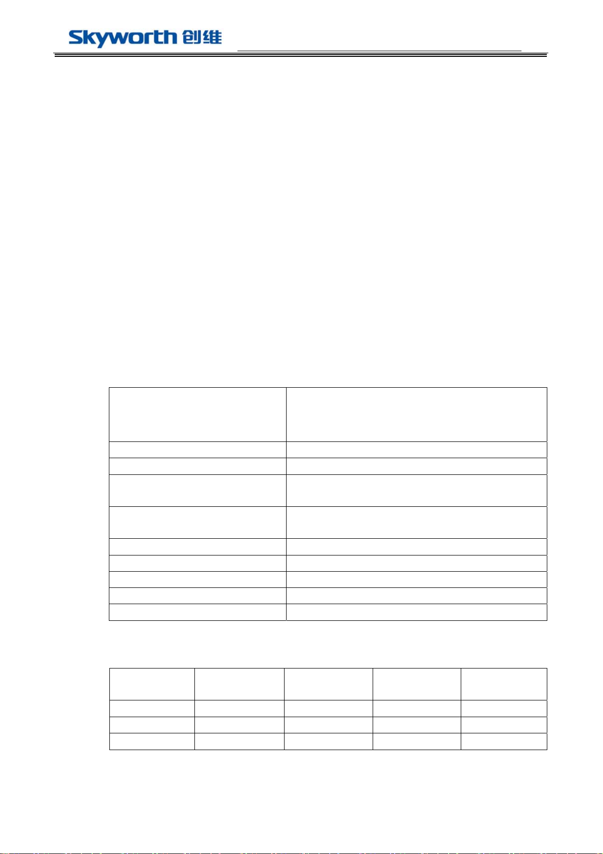
1.2.1 InputFeatures
Input voltage range 输入电压
90Vac to 264Vac
Normal voltage range 标称输入 100Vac to 240Vac
Frequency range 频率范围 50Hz/60Hz±5%
Max input ac current
满载输入电流
0.8Amax at 100VAC input & full load condition
Inrush current (cold start)
浪涌电流
50Atyp peak, 120Vac; 100Atyp peak, 220Vac
Efficiency(full load) 效率 85%min @ 220Vac,Full Load
Harmonic current 谐波电流 Meet GB17625.1-1998/IEC61000-3-2 class D
Leakage Current 泄漏电流 Less Than 0.75mA, 230Vac input
Standby Power Loss 待机功耗 ≦1W, 240Vac input,70mA Load
Input Fuse 输入保险 T3.15A L/250Vac
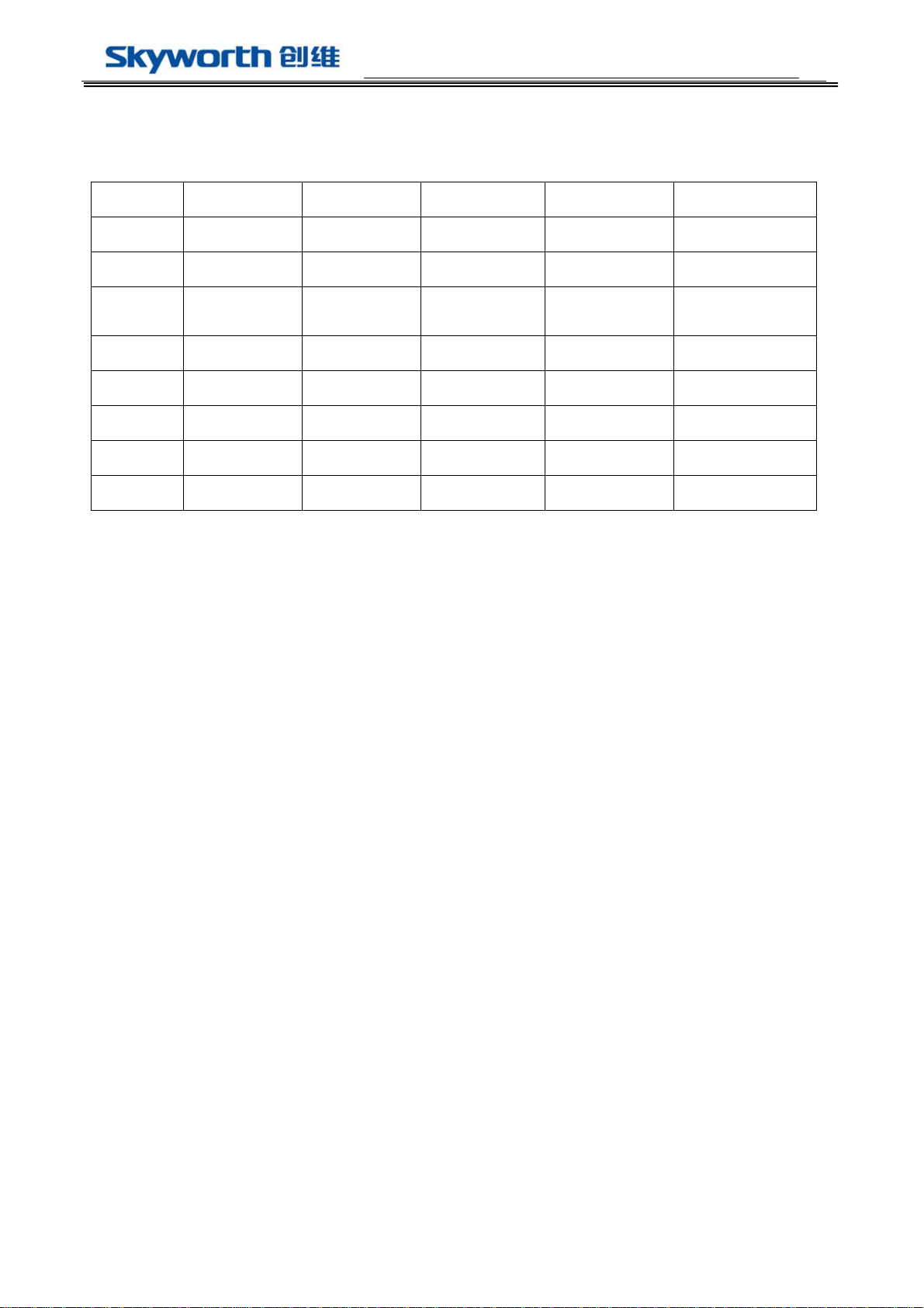
1.2.2 OutputFeatures
Output Voltage
输出电压
Regulation
调整率
Min. current
最小电流
Rated current
额定电流
Peak current
峰值电流
+12V +12V±7% 0.5A 2.5A 4.5A
+5V +5V±7% 0.5A 2A 2A
+5VSB +5VSB±7% 0.1A 0.1A 0.5A
Note:* pulse width within 100ms 脉宽小于 100 毫秒。

168P-P24TTU-20PowerSupplyServiceManual
2
1.2.3 OutputRippleandNoise
Output Voltage Ripple & Noise (Max.)
+12V 120mVp-p@25℃
+5V 100mVp-p@25℃
Note: 1) Measurements shall be made with an oscilloscope with 20MHz bandwidth.
示波器带宽须设置在 20 兆赫兹。
2) Outputs shall be bypassed at the connector with a 0.1uF ceramic capacitor and a 10uF
electrolytic capacitor to simulate system loading.
电源输出端并联 0.1uF 的陶瓷电容和 10uF 的电解电容来模拟负载测试。
2 CircuitDescriptions
2.1 OverallDiagram
2.2 InformationAboutEachSubCircuit
2.2.1 PWMcircuit:ON NCP1271P65G
MainFeatures:
a.Frequency Jittering For Softened EMI Signature
b.Internal High-Voltage Startup Current Source for Lossless Startup
c.Intrenal Latch for Easy Implementation of Overvoltage and Overtemperature Protection
d. Adjustable Skip Level
2.2.2 Inverte circuit:O2MICRO OZ9910BSN
MainFeatures:
a.Controller for high-voltage DC/AC converters
b.Soft start function
c.Built-in open-load protection,over-voltage protection,over-current protection,and TUV
protection。
transformer
EMI
Filter
Rectiflier
110-220V
A
C
+12V/2.5A
+5V/2.5A
OUTPUT

168P-P24TTU-20PowerSupplyServiceManual
3
3 MainChipDescriptions
3.1 PWMChip
3.1.1 ChipBlockDiagram
3.1.2 ChipPinDiagram
3.1.3 ChipPinFunctions

168P-P24TTU-20PowerSupplyServiceManual
4
3.2 DriverChip
3.2.1 ChipBlockDiagram
3.2.2ChipPinDiagram

168P-P24TTU-20PowerSupplyServiceManual
5
3.2.3ChipPinFunctions

168P-P24TTU-20PowerSupplyServiceManual
6
4 PCBTop/BottomLayerScreenPrinting
4.1 TopLayerScreenPrintingDiagram
4.2BottomLayerScreenPrintingDiagram
5Troubleshooting
5.1 CommonMalfunctionsAnalysis

168P-P24TTU-20PowerSupplyServiceManual
7
1、No+5VSBoutput
Ifno+5VSBoutputisdetected,please examiningwhetherIC7 isstillworkingnormally.IfitsVCCpin’s
voltageisregular,firstensurethattheIC’speripheralcircuitisworkingproperly,thenchecktheIC7.Ifthe
VCCpin’svoltageisnotnormal,examinethepowerlineof IC7.
2、+5VSBoutputnormal,butno+12V
Firstly, make sure PS_ON is in high electric level.
Secondly, make sure Q62 PIN1 is in low electric level with multimeter. If no, check all electric
circuit of Q63. If still found no problem, change Q62.
3、+5VSB abnormal voltage
Checktheloopof+5VSB, reference voltage of IC5(TL431), photo coupler IC6 sequentitally.
4、TroubleshootingDiagram
TroubleshootingDiagram1
No+5VSB
N Y
Y
N
Y
N
Examinethereason
AreIC5andIC6damaged?
Changethedamagedcomponent
ExaminethevoltageofC66:
127‐340V?
CheckperipheralcircuitsofIC7、Q61
ExamineF61,D61,TH6,
changethedamagedunit
If5Voutputisshort‐circuited

168P-P24TTU-20PowerSupplyServiceManual
8
5.2 DefinitionsofPortsandConnections
5.2.1 PIN10CN8SocketDefinition
NO. Pin Connection Function
1 ENA BL_ON/OFF
2 ADJ BL_ADJUST
3 GND GND
4 GND GND
5 GND GND
6 +5V +5V DC OUTPUT
7 +5V +5V DC OUTPUT
8 +12V +12V DC OUTPUT
9 +12V +12V DC OUTPUT
10 GND GND
11 GND GND
12 STB POWER_ON/OFF
13 GND GND
14 +5VSB +5VSB DC OUTPUT
Note: CN8 TYPE : 2.0mm
5.3 SparePartInventoryofCriticalComponent
No. SeriesNumber Model Position
Name/Functio
ns
/Parameter
SparePart
Number
Note
1 471U-N12711-0070 NCP1271P65G IC7 PWM chip
2 4600-K36730-0000 2SK3673-01M Q61 MOS tube
3 5100-066001-0000 BCK-60-01LP T61 transformer
4 4500-220A15-00 FCH20A15
D66
D67
D69
schottky diode
5 4734-P817C0-04 PC817C IC6 photocoupler
6 476K-Z99100-0160 OZ9910BSN IC1 Inverter chip
7 4600-P21030-0000 P2103ND5G Q1 Q2 MOS tube

168P-P24TTU-20PowerSupplyServiceManual
9
8 5100-092242-0000 BCK-2242WH T1 Inverter
transformer
5.4 Storage,TransportationandUsageCondition
5.4.1 Packaging
Allpackagesmustcontainname,modelnumber,labeling,manufacturingdateandqualitycertificateissued
byrelatedqualitycontroldepartment.
5.4.2Transportation
Transportbymeansofvehicle,shipandairplaneareallapplicable. During the transport, awnings, sun
protectionandgentlehandlingshouldalwaysbeapplied.
5.4.3Storage
Whennotused,productsshouldbestoredinsidethepackagingbox.Theacceptablestoragetemperatureis
between ‐40℃to55℃ with relative humidity between 10% to 95%. No hazardous gas, flammable or
explosivematerialsareallowedinthewarehouse,norarecorrosivechemicals.Inaddition,anykindofstrong
mechanicalvibration,shockandstrongmagneticfieldshouldbeavoidedduringthestorage. Also,packaging
boxisrequiredtobekeptatleast20cmfromtheground,50cmfromwalls, heat sources,windowsandair
inlets. Under the above circumstances, storage will normally expirein2years.Afull‐scaleexaminationis
expectedafterthat.

12345678
A
B
C
D
8
7654321
D
C
B
A
Title
Number RevisionSize
A3
Date: 19-Sep-2009 Sheet of
File: E:\
自制电源
\24
寸电源
\
原理图
\20090919(2).DDBDrawn By:
C65
2N2F AC250V-400V
R77
1K R71
10K
R79
1K
C74
50V/0.22UF
R72
3.9K
IC5
AS431A
L02
5UH
D63
EG01C
C68
50V/22UF
R66
100K
1
2
4
3
IC6
PC817C
R67 330
C72
50V/470PF
C73
50V/1000PF
FB
2
CS
3
HV 8
Drv 5
NC 7
VCC 6
Gnd
4
Dmg
1
IC7
NCP1271P
R61
47
Q61
2SK3673
D68
1N4148WS
C69
630V/0.0047UF
NC C67
2KV/100PF
R69
10
R82
4.7K
C77
25V/2200UF
C79
25V/1000UF
93
2
7
6
4
12
11
8
6:1 600UH
T61
R63
0.39/2W
C75
1KV/0.001UF
D66
20A/150V
C71
50V/1000PF
F61
3.15A L 250V AC
C62
224 L62
13mH
TH6
10
C64
102
C63
102
C61
224
D61
KBJ6JA
L61
13mH
R60
2.2M C66
450V/82UF
R74
3.9K
D65
BA158
R64
10K
R65
22
R73
68K
L01
5UH
C76
10V/2200UF C78
10V/1000UF
C70 1KV/0.001UF
D69 20A/150V
CN8
1
2
3
CN0
100-250V AC
L63
R24
47K
Q63
1815
NC C26A
1UF
R28
100
R26
1K
R25
100K
C26
0.1UF
GND
C12
47nF
C11
2.2uF
C5
1nF
C10
2.2uF
C9
2.2uF
C3
4700pF
R2
2.2M
C2
150pF/NPO
R1
1M/1%
R3
10K
NDRV2
3
PDRV1 16
GNDA
4
PDRV3 15
HSB 14
CT
5
VIN 13
VREF 12
ISEN 11
LCT
6
CMP_SST 10
VSEN 9
ADJ
7
ENA
8
PGND
2
NDRV4
1
OZ9910
U1
R8
130K
R5
2.2M
R4
51k R9
75k C4
1nF
R10
10
C6
0.1u
R7
0
R6
0
5V
OUT_5V
NDRV1
NDRV2
1
2
CNN1
1
2
CNN2
R20
470R/1%
R17
510R
1
2
CNN3
1
2
CNN4
C25
33nF
D3
1N4148
R18
1M C24
100nF
R16
100K Q3
2N7002
FB
C17
5PF/6KV
C21
3.3nF R13
30K
VS
C16
5PF/6KV
C20
3.3nF
R12
30K
C19
5PF/6KV
C23
3.3nF R15
30K
VS
C18
5PF/6KV
C22
3.3nF R14
30K
R11
1M C13
10nF
FB
VS
8
5
3
2
1
4
.
.
7
6
T1
22:2100:2100 320mH
PDRV1
NDRV1
+12V IN NDRV2
PDRV3
C14
4.7UF/50V
C15
4.7UF/50V
PS
3
ND 8
PG
4
ND 7
PD 6
PD 5
NG
2
NS
1
Q1 P2103N
PS
3
ND 8
PG
4
ND 7
PD 6
PD 5
NG
2
NS
1
Q2 P2103N
C80
1000uF/25V
PDRV1
PDRV3
R19
1k
R1A
150K/1%
NC C26
100nF
ENA
R22
0
R21
0
BL_ON/OFFBL_ADJUST
BL_ON/OFF
BL_ADJUST
D1
1N4148
D2
1N4148
D5
1N4148
D4
1N4148
D6
1N4148
D7
1N4148
D6720A/150V
R70 10 /2W
C60
50V/0.001UF
+5.1V OUT
168P-P24TTU-20
VER:00.00
D71 15V
Q62
P2003 Q61
P2003
1
2
3
4
5
6
7
8
9
10
11
12
13
14
BL_ON/OFF
BL_ADJUST
GND
GND
GND
+5V
+5V
+12V
+12V
GND
GND
POWER-ON/OFF
GND
STANDBY-5V
R27
470
R28
100K
D81N4148
C27
1UF
R30
1K
NC C27A
1UF
R29
470
VDR601
PQ0270
R58 220
R59 220
VDR602
VDR603 GS35
GS35
Table of contents
Other Skyworth Power Supply manuals