SLD Security & Communications PRLCD User manual

版本:V2.1
Solar street light controller remote
control user manuel
Guangzhou Lingda New Energy Technology Co.,Lt d
2020

Version:V2.1
1/11
Contents
1. Product description................................................................................................................. 2
2. Key Description...................................................................................................................... 2
3. Instructions..............................................................................................................................3
3.1 System setting...............................................................................................................3
3.2.Check system info......................................................................................................4
3.4.View current parameters............................................................................................ 8
3.5. Remoter 2.4G ScanningTips........................................................................................8
6. Controller indicator status list.............................................................................................. 12
7. Battery parameter setting (for reference)............................................................................. 13

Version:V2.1
2/11
1. Product description
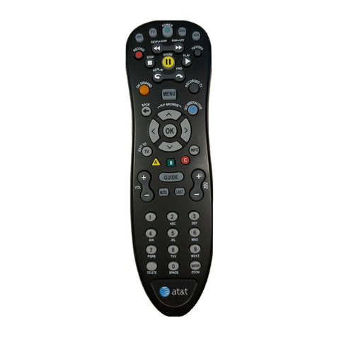
The PRLCD remote control can read parameters from the machine, or set parameters to
the machine. This remote control uses 2 AA dry batteries for power supply, and communicates
with the controller by infrared/2.4G.
Note:
①This remote control is only applicable to our seventh generation and later solar street
light control and charging and discharging integrated machines. Please confirm the controller
version before use! ! !
②In order to avoid mutual interference between remote controls, please ensure that only
one remote control is turned on in the same area! ! !
③To avoid sending wrong parameters due to misoperation, the send button is only valid
in the sending parameter interface! ! !
2. Key Description
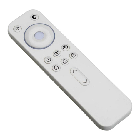
LCD display: display all data interface.
Power Key: Press once, the power is turned on, and the LCD starts to display data. Long
press for 2 seconds to release, the remote control will turn off the power.
Up Key: Press once, the cursor moves up or the number increases. When changing the value,
long press this key, the number will increase rapidly.

Version:V2.1
3/11
Sending Key: When the parameters are set, press this button, the remote control sends
wireless data for parameter setting.
Signal OFF Key: make the controller enter sleep state.
Enter key: When modifying data, press this key to form a modification shadow and enter the
modification mode. When the modification is completed, press again, the modification shadow
disappears, and the modification mode is exited.
Signal ON Key: wake up the controller and make the controller enter working state.
Search Key: In the main interface, enter the search interface of real-time data, send
parameters, and read parameters to press the search button to be effective, and the remote control
starts to search for the ID of the 2.4G controller that is running.
Down Key: Press once, the cursor moves down or the number decreases. When changing the
value, long press this key, the number will decrease rapidly.
Back key: Press once to exit this interface and return to the previous interface.
3. Instructions
3.1 System setting
In the main interface, move the cursor to "System Settings" and press "□" to enter the system
settings interface.
1) Language options: You can select the language, switch between Chinese and English.
2) Model options: Choose the corresponding model according to the controller model. After
turning on the remote control, please perform model selection operations before proceeding.
M6 series: M660 / M660S;
P3 series: P315 / P320 / P330;
M3 series: M340 / M340S / M360;
P12 series: P1220 / P1230 / P1240 / P2410 / P2410S;
M12 series: M1280 / M2410 / M2415.

Version:V2.1
4/11
3) Communication mode: There are currently three communication modes, infrared
communication, 2.4G scanning and 2.4G broadcasting. The corresponding mode should be
selected according to the communication mode of the controller.
Communication distance: only valid for 2.4G scan mode and 2.4G broadcast mode, super far (48
meters), far (33 meters), normal (24 meters), near (15 meters), super near (3 meters) (Note: The
above distance is tested when there is no obstruction between the controller and the remote control,
and there will be some deviation from the actual use distance)
3.2.Check system info
3.2.1 2.4G Scanning:
In the main interface, move the cursor to "real-time data" and press "□" to enter the real-time
data search interface. If the interface prompts, press the search button, and press the search
button to search for the controller ID (if some controllers are currently searched) ID, you can
also search again), after searching the controller ID, select the controller ID that needs to
view the operating information, press the "□" key to enter the real-time data interface, and
view the current controller's real-time data and alarm information.
main menu Search interface Search success interface SystmInfo interface
Note:
1) In the real-time data search interface, the ******* option is invalid, so the cursor will not
jump to the ******* option.
2) View real-time data can only be viewed one by one.
3) "Success" is displayed behind the controller ID, which means that the operating
information of the controller has been checked.
4) If the communication is successful, the upper right corner will now **(**)on, the first
number is the number where the ID is located, and the number in brackets is the last two
digits of the ID

Version:V2.1
5/11
5) The model of the current controller is automatically recognized by the remote control, and
there is no need to select the model on the remote control.
3.2.2. Infrared communication:
Point the remote control at the controller's infrared emitting tube and receiving tube. On the
main interface, move the cursor to "real-time data" and press the " □" key to enter the
real-time data interface to view real-time data and alarm information.
3.2.3. 2.4G broadcast:
1) When there is only one controller within the communication range of the remote control,
you can use the "View real-time data" function in 2.4G broadcast mode. On the main
interface, move the cursor to "Real-time data" and press the " □" key to enter the
real-time data Interface to view real-time data and alarm information.。
2) When there are two or more controllers within the communication range of the remote
control, the "View real-time data" function of 2.4G broadcast mode cannot be used,
please switch to 2.4G scan mode.
3.3.Send Parameters
3.3.1. 2.4G Scanning:
In the main interface, move the cursor to "Send Parameters" and press " □" to enter the
search interface of sending parameters. If the interface prompts, press the search key, and
press the search key to search for the ID of the controller (if some controllers are currently
searched) ID, you can also search again), after searching for the controller ID, select the
controller ID or all sending options that need to set parameters, and press the " □" key to
enter the corresponding sending parameter interface.
main menu Search interface Search success interface
1. Send all: In the search interface, move the cursor to "00 Send all", press the "□" key to
enter the all-send interface, move the cursor to the corresponding parameter position, and press the
"□" key, when the option is shaded , Press " ↓ ↑ " key to adjust the value, press " □" key to

Version:V2.1
6/11
confirm after setting.
Search success interface Parameter setting interface Setup complete interface
1) Press the send button to set the parameters of the searched controllers one by one.
During the setting process, pressing any key at this time is invalid until the setting is
completed, the success of the setting will be displayed behind the ID.
2) Press the shutdown button, and the searched controllers will be shut down one by
one. During the setting process, pressing any key at this time is invalid until the setting
is completed, the success or failure of the setting will be displayed behind the ID.
3) Press the power button, and the searched controllers will be set to power on one by
one. During the setting process, pressing any key at this time is invalid until the setting
is completed, the success of the setting will be displayed behind the ID.
②.Single setting: In the search interface, move the cursor to the ID of the parameter that
needs to be set, press the "□" key to enter the single setting interface, move the cursor to the
corresponding parameter position, and press the "□" key, when the option is shaded Time,
press "↓↑" key to adjust the value, press "□" key to confirm after setting.
Search success interface Parameter setting interface Setup complete interface
1) Press the send button to set the parameters of the controller with the current ID. When
you hear a long beep from the controller, the LCD screen of the remote control will also
display the sending success, which means that the parameters have been written
successfully.

Version:V2.1
7/11
2) Press the shutdown button to set the shutdown settings for the controller with the
current ID. When you hear a long beep from the controller, the LCD screen of the remote
control will also display the transmission success, which means that the parameters have
been written successfully.。
3) Press the power button to set up the controller with the current ID. When you hear a
long beep from the controller, the LCD screen of the remote control will also display the
sending success, which means that the parameters have been written successfully.
3.3.2. Infrared communication:
Aim the remote control at the controller's infrared emitting tube and receiving tube, on
the main interface, move the cursor to "Send parameter", press the " □" key to enter the
sending parameter interface, move the cursor to the corresponding parameter, and press "□"
When the option is shaded, press the " ↓ ↑ " key to edit the value, press the " □" key to
confirm after setting, and press the send key to send the parameter after editing.
3.3.3 2.4G broadcast
In the main interface, move the cursor to "Send parameter", press the "□" key to enter
the transmission parameter interface, move the cursor to the corresponding parameter, press
the "□" key, when the option is shaded, press "↓↑" ”Key to edit the value, press the “□” key to
confirm after setting, and press the send key to send the parameter after editing. The 2.4G
broadcast mode will synchronously send parameters to all the nearby controllers that are
searched. The speed is faster than the 2.4G search mode. The 2.4G broadcast mode does not
display the controller ID.
1) Press the send button to set the parameters of all the controllers in the current
communication range. If the parameters are set successfully, all the indicators of the
controller will flash and the controller in the driving state will control the street lights to go
out and then turn on again, not in the state of driving lights The lower controller will control
the street light to turn on and then off, which means that the parameter has been written
successfully.
2) Press the shutdown button to perform shutdown settings for all controllers within the
current communication range. When the controller indicator is off, it means the shutdown is
successful.
3) Press the power button to set up all the controllers in the current communication
range. When the controller indicator lights or flashes, it means the power on is successful.

Version:V2.1
8/11
3.4.View current parameters
3.4.1. 2.4G Scanning:
In the main interface, move the cursor to "Read Parameters" and press the "□" key to enter
the search interface for reading parameters. If the interface prompts, press the search key, and
press the search key to search for the controller ID (if part of the current search is found)
Controller ID, you can also search again), after searching the controller ID, select the
controller ID that needs to read the parameters, press the "□" key to enter the corresponding
read parameter interface, and you can view the current controller at this time Parameters
under。
main menu Search interface Search success interface current parameters
3.4.2. Infrared communication:
Aim the remote control at the controller's infrared emitting tube and receiving tube, on the
main interface, move the cursor to "read parameters", press the " □" key to enter the read
parameter interface, and view the street lamp parameters.
3.4.3 2.4G broadcast:
1) When there is only one controller within the communication range of the remote control,
you can use the "read parameters" function in 2.4G broadcast mode. On the main interface,
move the cursor to "read parameters" and press the "□" key to enter the reading Parameter
interface, view street lamp parameters.
2) When there are two or more controllers within the communication range of the remote
control, the "read parameter" function of 2.4G broadcast mode cannot be used, please switch
to 2.4G scan mode.
3.5. Remoter 2.4G ScanningTips
1)When setting parameters, in order to wake up the controller, it is best to press the send
button after staying on the sending interface for 1-2 seconds.
2) When the controller is searched, the controller will be sorted according to the

Version:V2.1
9/11
controller ID from small to large.
3) The search interface for real-time data, sending parameters, and reading parameters are
synchronized.
4) The real-time data, sending parameters, and reading parameter interfaces can all be
individually set for startup and shutdown.
5) When setting up the controller, make sure that besides the controller that needs to be
set up, no other controllers are working, to avoid incorrect or under-setup.
6) When some nearby controllers are damaged and cannot communicate, all nearby
controllers can be shut down to find the damaged controller.
4. Related concepts
Battery undervoltage: When the battery voltage is lower than the set undervoltage protection
voltage, the output will be prohibited
Recovery voltage: It means that the output is allowed only when the battery voltage needs to be
higher than the set recovery voltage again after undervoltage
Light control voltage: when the photovoltaic voltage is lower than the set PV voltage for lighting,
the light will automatically turn on; when the photovoltaic voltage is higher than the set lighting PV
voltage, the light will be turned off.
Time control mode: refers to the entire lighting period can be divided into 5 time periods, the
brightness of each time period (0-9H can be set) can be set according to actual needs to achieve the
purpose of energy saving and power saving.
Induction mode: When the infrared or microwave probe senses a person, the brightness of the
lamp will become brighter, and the brightness of the lamp will automatically dim after the person walks.
The brightness of the person and the brightness of the person can be adjusted according to actual needs
Adjustment.
Morning mode: refers to the light on during the time period before dawn.
Power saving mode: When power saving mode is turned on, the controller will adjust the output
current according to the battery voltage, as shown in the following example:
11.1V Examples of ternary lithium batteries:
Assume that the 11.1V ternary battery is set as follows:
Charge voltage: 12.5V
Undervoltage protection: 9V
Recovery voltage: 11.1V
Power saving mode: On (if you choose to turn off, power saving and super power saving are not
started)
Start to save power: 11V (adjustable)
Super power saving: 10V (adjustable)
It is divided into five sections at 10V-11V, and each section is derated by 15%

Version:V2.1
10/11
11-12.5V: 100% light on the original setting
10.8-11V: On the basis of the original setting *85%
10.6-10.8V: On the basis of the original setting *70%
10.4-10.6V: On the basis of the original setting *55%
10.2-10.4V: On the basis of the original setting *40%
10-10.2V: On the basis of the original setting *25%
9-10V: minimum power drive light
<9V: Enter under-voltage protection without driving lights
The principle is as follows:
Battery voltage is at the beginning of power saving-equalizing charge voltage: drive the light
normally according to the set current
Battery voltage is at the beginning of power saving-super power saving: reduce power in 5 equal
parts
The battery voltage is in super power saving-battery undervoltage: the minimum power to drive
the light
Battery voltage is lower than under-voltage protection: no drive light
5. Remoter Lock
Since there are many models of remote control that can be set, and the parameter
modification is relatively simple, in order to prevent users from misoperation or set
incorrectly set parameters to the controller, it is recommended that a unified batch of
controllers correspond to one remote control. The remote control is locked. After all the
settings of this batch of machines are completed, unlock it, and set up another batch of
controllers after re-adjusting the parameters.
When the remote control is locked, the parameters of the controller can be read and
written through the remote control, but the parameters set in the remote control cannot be
modified.
The lock/unlock operation method is as follows:
Press the "search key", " □" key and "return key" at the same time. When you hear a
long beep, it means that the remote control has been locked; when it is locked, press the above
three keys again at the same time and you hear A long beep means that the remote control has
been unlocked

Version:V2.1
11/11
Figure 3-12 Schematic diagram of remote control lock/unlock
As shown in Figure 3-12 above, the user presses the three keys in the red box at the same
time and hears a beep to lock the remote control; in the locked state, press these three keys at the
same time, It can be unlocked after hearing the "di" sound.

Version:V2.1
12/11
6. Controller indicator status list
The following table is a list of indicator lights. Users can judge the system status according to
the flashing conditions of the indicator lights. If the system is faulty, the problem can be locked
and solved according to the indicator status.
Item Machine state
Yellow Indicator
(RUN)
Green Indicator
(Charge/CHG)
Red Indicator
(Discharge/DISCHG)
1 Start initialization Flashing Flashing Flashing
2 Normally Charge Always bright Always bright extinguish
3 Normally drive Always bright extinguish Always bright
4 Machine standby Always bright extinguish extinguish
5 Parameter setting error Slow Flashing Slow Flashing extinguish
6 LED open or short extinguish extinguish Quick Flashing
7 Reverse battery extinguish Quick Flashing extinguish
8Battery waiting to exit
undervoltage extinguish Slow Flashing extinguish
9 Drive time up extinguish extinguish Slow Flashing
10 Battery voltage
overvoltage Slow Flashing extinguish extinguish
11 PV overpressure Quick Flashing extinguish extinguish
12 PV reverse connection Quick Flashing Quick Flashing extinguish

Version:V2.1
13/11
7. Battery parameter setting (for reference)
Lifepo4
Series
Rated
Voltage
Charge
voltage
Battery
undervo
ltage
Clean
undervo
ltage
Light
control
voltage
Start
saving
power
Super
saving
power
1 3.2 3.6 2.6 3.1 1-3 3.2 3.0
4 12.8 14.4 10.8 12 4-5 12.5 12
8 25.6 28.8 21.6 24 8-10 25 24
Ternary
lithium
Series
Rated
Voltage
Charge
voltage
Battery
undervo
ltage
Clean
undervo
ltage
Light
control
voltage
Start
saving
power
Super
saving
power
1 3.7 4.15 3.0 3.5 1-3 3.7 3.5
3 11.1 12.5 9 10.5 4-5 11.1 10.5
6 22.2 25 18 21 8-10 22.2 21
Lead
acid
Series
Rated
Voltage
Charge
voltage
Float
voltage
Battery
underv
oltage
Clean
underv
oltage
Light
control
voltage
Start
saving
power
Super
saving
power
6 12 14.4 13.6 11 12.5 4-5 12.5 12
12 24 28.8 27.2 22 25 8-10 25 24
The above parameters are for reference only, users can make other settings according to the actual
characteristics of the battery.
Table of contents
