13
SEP 240/300 TC 1.0.3 - 2017
14
SP 155 TCi / SP 200 TCi / SP 240 TCi / SP 285 TCi
2.5 - 2006
Einbau des Elektromotors
D
1. Die 4 Bolzen in der Motorhalterung enfernen.
2. Die Antriebsachse im Getriebegehäuse und die Motorachse so
drehen, daß die elastische Kupplung dazwischen paßt.
3. Den Motor vorsichtig auf die Motorhalterung aufsetzen. Der
Motor ist sehr schwer!
4. Mit den 4 Bolzen Motor und Motorhalterung lose verschrauben.
5. Abmessen und die beiliegende Motorabstützung so anbringen,
daß der Motor anliegt. Die Abstützung muß gut am Boot be-
festigt werden. Die beiliegende Gummiplatte vor dem fest-
ziehen zwischen Motor und Abstützung bringen.
6. Mit den 4 Bolzen Motor und -halterung miteinander verschrauben.
7. Die Befestigungsschraube im unteren Teil der elastischen
Kupplung festziehen.
8. Überprüfen, ob sich die Propeller frei im Tunnel drehen lassen.
Aufgrund der Getriebeübersetzung und des Motors sollte das
Systemdies etwas schwergängig sein.
In manchen Fällen, z.B. bei flachem Rumpf oder im gerwerblichen
Einsatz (z.B. Fischfang) empfehlen wir, den Propeller durch ein
Gitter vor der Tunnelöffnung zu schützen (Fig. 3). Dieses sollte auf
ein Minimum beschränkt und so stromlinienförmig wie möglich sein,
da ansonsten die Leistung des Thrusters reduziert wird.
NB ! Wir empfehlen, auf das Getriebegehäuse Anti-Fouling
aufzutragen. Nicht auf die Propellerachse, Zinkanoden oder
den Verschluß des Getriebegehäuses auftragen.
NB ! Den Thruster nur für den Bruchteil einer Sekunde betätigen
wenn dieser nicht im Wasser ist.
NB ! Wird der Elektromotor eingebaut, falls das Boot noch in Bau
ist, so muß dieser abgedeckt werden, um eine Verschmutzung
von Relais und Motor zu verhindern. Diese Abdeckung muß
vor Benutzung des Thrusters entfernt werden.
1. Remove the 4 bolts in the motorbracket.
2. Turn the driveshaft in the gearhouse and the motorshaft so the
key in the shaft and the keyway in the flexible coupling are in-line.
3. Place the motor gently onto the driveshaft and the motor
bracket. Be careful, the motor is very heavy!
4. Fasten the motor loosely to the bracket with the provided bolts.
5. Measure up and fit the provided motor support so that the
motor sits tightly in it. The support must be sturdily fastened to
the boat. Make sure to put the provided rubber between the
support and the motor before tightening the strap.
6. Tighten the 4 bolts holding the motor to the motorbracket.
7. Tighten the set-screw in the lower part of the flexible coupling.
8. Check the system by turning the propeller, it will be a little hard
to turn (because of the gear reduction and the motor), but you
should be able to turn it by hand.
In some cases (shallow installation or workboat / fishingboat only) we
recommend to protect the propeller by mounting a grid in the tunnel
opening (Fig. 3). It is important to keep a grid to a minimum and as
streamlined for the thrusters waterflow as possible, as it will
decrease the effect of the thruster.
NB ! Paint the gearhouse and propeller with antifouling for pro-
pellers to prevent growth of barnacles or similar which would
reduce the performance dramatically. Do not paint the pro-
peller shaft, the zincanodes or the end face of the gearhouse.
NB! Do not run the thruster for more than very short bursts with-
out being in the water.
NB ! If the boat is still being built when the electromotor is installed, it
must be covered up to avoid dust from the building going into
the motor and the solenoids. This cover must be removed
before the thruster is being used.
Fitting the electromotor
GB
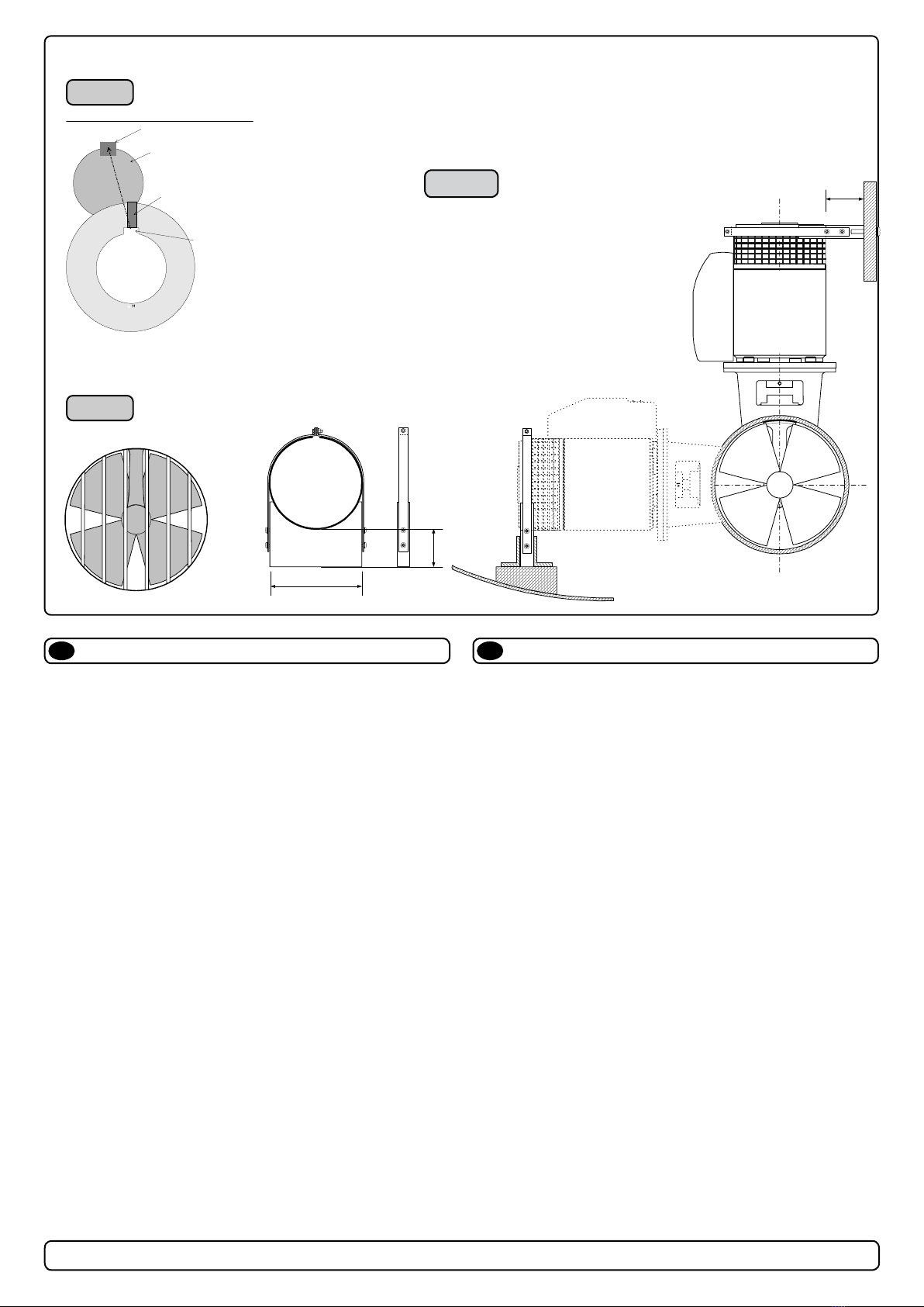
Fig. 3
Fig. 1
Ke
in driveshaf
Driveshaft from
gearhouse
Keyway in
flexible-
coupling
Flexible-coupling
Set screw
Fig. 2
SP 200 TCi
SP 240 TCi
SP 285 TCi
SP 200 TCi
SP 240 TCi
SP 285 TCi
For safety the motor of the Sidepower SP200TCi / SP240TCi / SP285TCi must
be fastened in all installation positions with the included motor-support.
1. Fit the motor to the already fitted motorbracket on the tunnel.
2. Fasten the support to a bulkhead / the boat in a correct position to support the
motor firmly. The support can be fastened anywere on the motor as long as it
does not interfer with the cables, but we do advice to fit it on the top as shown
in these drawings.
3. Be sure to use the included rubber strip between the support and the motor.
88mm
212mm
88mm
Montering av elektromotor
N
Fitting the electromotor
EN
1. Remove the 4 bolts in the motorbracket.
2. Turn the driveshaft in the gearhouse and the motorshaft so the
key in the shaft and the keyway in the exible coupling are in-line.
3. Place the motor gently onto the driveshaft and the motor
bracket. Be careful, the motor is very heavy!
4. Fasten the motor loosely to the bracket with the provided bolts.
5. Measure up and t the provided motor support so that the
motor sits tightly in it. The support must be sturdily fastened to
the boat. Make sure to put the provided rubber between the
support and the motor before tightening the strap.
6. Tighten the 4 bolts holding the motor to the motorbracket.
7. Tighten the set-screw in the lower part of the exible coupling.
8. Check the system by turning the propeller, it will be a little hard
to turn (because of the gear reduction and the motor), but you
should be able to turn it by hand.
In some cases (shallow installation or workboat / shingboat only) we
recommend to protect the propeller by mounting a grid in the tunnel
opening (Fig. 3). It is important to keep a grid to a minimum and as
streamlined for the thrusters waterow as possible, as it will
decrease the eect of the thruster.
NB! Paint the gearhouse and propeller with antifouling for propellers to
prevent growth of barnacles or similar which would reduce the perform-
ance dramatically. Do not paint the propeller shaft, the zincanodes or the
end face of the gearhouse.
NB! Do not run the thruster for more than very short bursts without being
in the water.
NB! If the boat is still being built when the electromotor is installed, it
must be covered up to avoid dust from the building going into the motor
and the solenoids. This cover must be removed before the thruster is
being used.
1. Fjern de 4 boltene i i motorbraketten.
2. Plasser motoren på braketten. Plasser motoren slik at de releene er
tilgjengelige for tilkobling senere. Ta hensyn til at motoren er tung når
den bæres og håndteres.
Sjekk at kilespor i gummikobling og kile på aksel er på linje.
3. Fest motoren til braketten med de re boltene (Fig. 1).
4. Uansett plassering trenger motoren på SEP240 å støttes opp. Jamfør
tekniske tegninger.
5. Sjekk at børstefjærene sitter korrekt på børstene (gjøres ved å se
gjennom gitteret på siden av motoren).
I visse tilfeller (ved grunne installasjoner, ske / arbeidsfartøy fartøy)
anbefaler vi å beskytte propell og girhus ved å montere et gitter foran
tunnelåpningene (Fig. 2). Det er da meget viktig å beholde strømlinjefor-
men, og å begrense gitteret til et minimum. Feil installasjon kan begrense
skyvekraften med 10%.
NB ! Påfør bunnsto på girhus og propell for å unngå vekst som kan virke
sterkt hemmende på trusterens eekt. Sinkanoder propellaksling og tet-
ninger skal ikke stoes.
NB ! Trusteren må kun kjøres i meget korte perioder når den ligger på
land.
NB ! Hvis båten fortsatt er under bygging når trusteren blir montert må
motoren dekkes til for å unngå at støv og lignende trenger inn i girhus og
elektromotor. Dekket må fjernes før motoren tas i bruk.
13
SP 155 TCi / SP 200 TCi / SP 240 TCi / SP 285 TCi
2.5 - 2006
1. Für genügend Öldruck im Getriebegehäuse muß der Getriebe-
ölbehälter oberhalb der Wasserlinie montiert werden. Der Ab-
stand muß mind. 20% der Distanz von Wasserline zum Zentrum
des Tunnels betragen.
2. Den Schlauch für das Öl am Vorratsbehälter und am vorge-
sehenen Nippel der Motorhalterung befestigen. Die Schlauch-
klemmen anziehen. Sicherstellen, daß das Öl ungehindert und
direkt in das Getriebegehäuse fließen kann.
3. Den Vorratsbehälter mit Getriebeöl EP90 füllen.
4. Wenn das Getriebegehäuse nicht schon vorher befüllt wurde,
die Ölablaßschraube (1) öffnen, bis Öl austritt, dann sicher
festziehen. Immer die Kupferdichtung (1) verwenden.
5. Den Klebestreifen über der Propellerfixierung (2) entfernen.
Falls auf den Propellerwellen nicht mehr ausreichend wasser-
festes Fett vorhanden ist, neues bzw. mehr Fett auftragen. Da-
durch können die Propeller später ohne Probleme abge-
nommen werden.
6 Die Propeller aufstecken und bis zum Anschlag schieben. Der
mit LH gekennzeichnete Propeller muß auf der Backbord Seite
stehen, der mit RH gekennzeichnete Propeller auf der Steuer-
bord Seite. Die Propeller müssen sich frei drehen können und
im Tunnel möglichst zentriert sein.
7. Die Befestigungsschraube (3) anziehen.
8. Die Zinkanode (4) mit der Befestigungsschraube (5) anbrin-
gen. Locktite o.ä. verwenden, damit sich die Schraube durch
die Rotation des Propellers nicht löst.
Teile:
1 : Ölablaßschraube mit Dichtung 4 : Zinkanode
2 : Propellerfixierung 5 : Schraube für Zinkanode
3 : Propellermutter
Ölvorratsbehälter & Propeller
D
Fitting oil tank & propeller(s)
GB
1. Fit the oil tank above the waterline by atleast 20% of the distance
from the waterline to the centre of the tunnel. This is for ensuring
enough overpressure of oil in the gearhouse.
2. Fit the oil tube to the tank and the feed pipe in the motor
bracket. Tighten the tube clamp screws. Make sure that the oil-
tube has no loops that makes an airlock to stop the oil flow and
has a good angle to allow the oil to flow freely into the
gearhouse.
3. Fill the oil tank with gear oil type EP90.
4. If you did not prefill the gearhouse, open the oil drain screw (1)
until oil comes through, then tighten it securely and make sure
that the copper gasket (1) is present.
5. Remove the tape holding the keys (2) to the propeller shafts.
Check that the waterproof grease applied at the factory is still
on both propeller shafts. If not, apply new / more. This is to
ensure you can get off the propellers after a long time.
6. Fit the propellers to the shafts with the LH marked propeller on
the port side and the RH marked propeller on the starboard
side. Turn them to again make sure they move freely and as
much in the centre of the tunnel as you have managed.
7. Tighten the lock nuts (3).
8. Place the zinkanode (4) in its designated position and tighten
the zincanodes holding screw (5). Apply a thread glue (Locktite
or similar) to ensure that the zincanodes holding screw does
not un-screw itself from the propellers rotation.
Parts description:
1 : Oil drain screw with washer 4 : Zinc anode
2: Keys 5 : Screw for zincanode
3 : Propeller lock nut
Fig. 2
nOil drain screw with washer
oKeys
pPropeller lock nut
qZinc anode
rScrew for zinc anode
Fig. 1
For safety the motor of the Sidepower SEP240/300Tc must be se-
cured in all installation positions with the included motor support.
Fig. 2


