2592 8 72 0 21
-
SRP L&V 130 & 170 & 210 & 250
DECLARATION OF CONFORMITY
Sleipner Motor AS
P.O. Box 519, Arne Svendsensgt. 6-8
N-1612 Fredrikstad, Norway
Declare that this product with accompanying standard control systems complies with the
essential health and safety requirements according to:
DIRECTIVE 2013/53/EU
DIRECTIVE 2014/30/EU
DIRECTIVE 2014/35/EU
MC_0020
Planning Installation Considerations and Precautions .............. 3
Thruster Measurements ............................................................ 4
Thruster Specications.............................................................. 5
Technical Specications ............................................................ 5
Positioning of the Retract Thruster............................................ 6
Installation Instructions
Thruster Installation Considerations and Precautions............... 7
Marking and Trimming of SRF Flange....................................... 8
Installation Pre-check ................................................................ 9
Required Modications After Pre-check .................................. 10
SRF Flange Installation ......................................................... 11
Motor House Installation.......................................................... 12
Hatch Installation..................................................................... 13
Motor to House Installation...................................................... 14
Thruster Electrical Installation ................................................. 15
Electrical Specications........................................................... 16
Control Panel Cable Installation ............................................. 17
S-link Planning & Precautions ................................................ 18
Technical Wiring Diagram ............................................... 19 - 20
Check drive shaft alignment ................................................... 21
Calibrate drive shaft alignment ............................................... 21
Actuator Conguration ............................................................ 21
LED Indication ........................................................................ 21
Control Panel Installation ........................................................ 22
Checklist for DC and IP Thrusters ...................................... 23
Service and Support ...................................................... 24
Product Spare Parts and Additional Resources ............... 24
Warranty statement ...................................................... 24
Contents
EN
MC_0066
Planning Installation Considerations and Precautions
EN
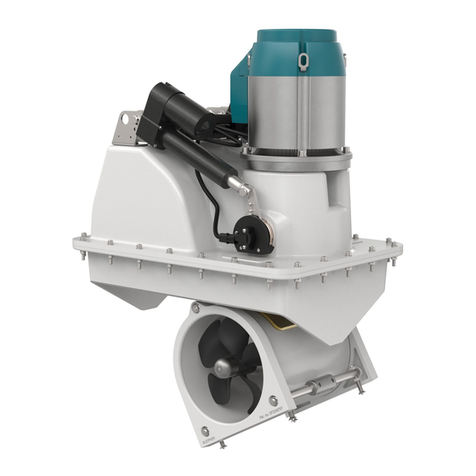
• If the height of the room you are installing the product is limited consider the three different confi guration designs.
- Angled
-Horizontal
-Vertical
• The thruster must NOT be installed in compartments that require ignition proof electric equipment. If necessary, make a separate compartment.
(NB: If installing an IP assembly, it has been tested to be fully ignition protected so that it can be installed in areas with possible
explosive gases in accordance with ISO 8846)
• The electro motor will generate some carbon dust so any storage compartment must be separated from the thruster to prevent nearby items
from becoming dusty/ dirty. (NB: IP version motors do not generate dust)
• Installing the electro motor in a small compartment must be ventilated to ensure cooling of the electro motor.
• Do not install the thruster in a position where you need to cut a stiffener/ stringer/ support for the hull integrity without checking with the boat
builder this can be done safely.
• The electro motor, its components, contacts/ plugs or other joints in the control cables must be mounted so they will remain dry at all times.
• We advise painting the gear house and propellers with anti-fouling. (NB: Do not paint the anodes, sealing or propeller shafts)
• Do not fi nish the inside of the tunnel with a layer of gel-coat/ topcoat or similar. There is only room for a thin coat of primer and two layers of anti-
fouling between the tunnel and the props.
• Don’t install the electro motor at close range to easily flammable objects as it will reach over 100°C before the temperature switch is activated.
• Do not store items close to the thruster motor as it can reach 100°C. Any loose items near the thruster motor can cause problems with electrical
wiring coming loose and short-circuiting.
IMPORTANT
Stern mounted retract thrusters must not be installed to conflict with the main boat propellers or its water trail. (NB: consult a naval architect
for an exact position.)
It is the installers responsibility
When installing Sleipner equipment follow the outlined regulations/ classifi cation rules (electrical/ mechanical) according to
international or special national regulations. Instructions in this guide cannot be guaranteed to comply with global electric/
mechanic regulations/ classifi cation rules.
Follow all health and safety laws in accordance with their local outlined regulations/ classifi cation rules.
Before installation, it is important that the installer reads this guide to ensure necessary acquaintance with the product.
The recommendations made in this manual are guidelines ONLY, and Sleipner Motor AS (Sleipner) strongly recommend that before
installation, advice is obtained from a naval architect familiar with the particular vessel and regulations/ classifi cations.
This manual is intended to support educated/ experienced staff and is therefore not suffi cient in all details for professional
installation. (NB: These instructions are only general instruction. If you are not skilled to do this work, please contact professional
installers for assistance.)
All electrical work must be done by a licensed professional.
Faulty installation of Sleipner products will render all warranty given by Sleipner Motor AS void. MC_0038
Products
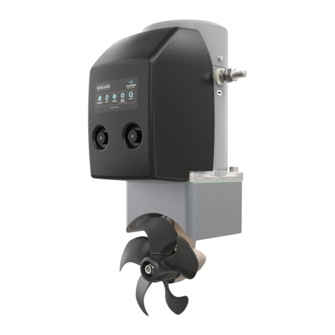
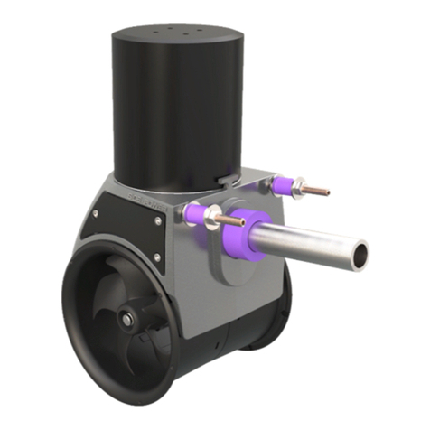
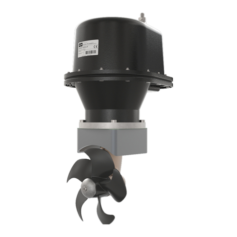
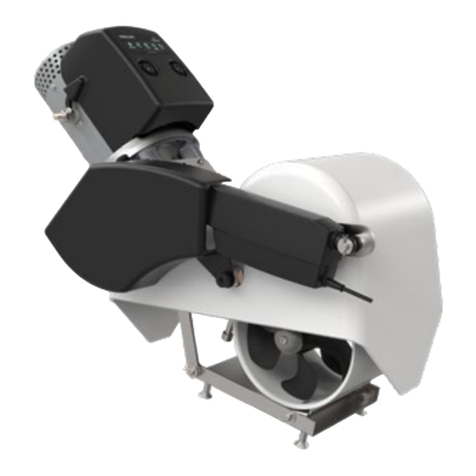
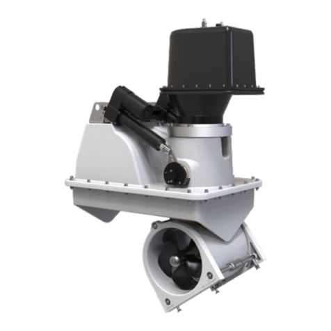
SRLP130/250T-12V - SRLP130 Retract thruster 12V
SRLP170/250TC - SRLP170 Retract thruster 24V
SRLP130/250T-24V - SRLP130 Retract thruster 24V
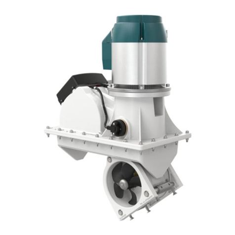
SRVP170/250TC - SRVP170 Vertical Retract 24V
SRVP210/250TC - SRVP210 Vertical Retract 24V
SRVP130/250T-12V - SRVP130 Vertical Retract 12V
SRVP130/250T-24V - SRVP130 Vertical Retract 24V
