10
Operating Instructions
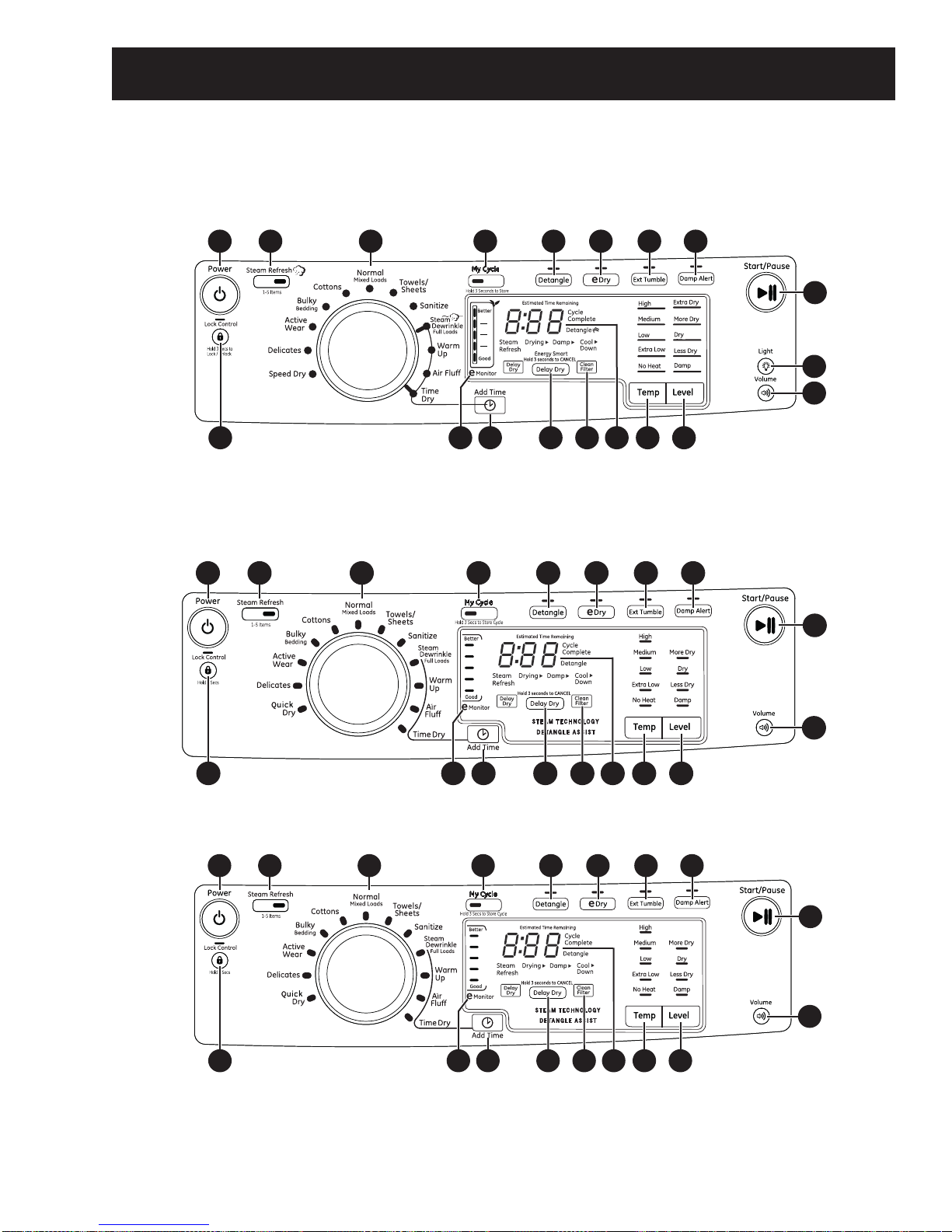
Power
Press to “wake up” the display. If the display is active, press to turn the dryer off.
NOTE: Pressing Power does not disconnect the appliance from the power supply.
1
Normal/Mixed Loads For loads consisting of cottons and poly-blends.
Cottons For cottons and most linens.
Bulky/Bedding For large coats, bed spreads, mattress covers, sleeping bags, blankets, comforters, jackets, small
rugs, and similar large and bulky items.
Active Wear Clothing worn for active sports exercise and some casual wear. Fabrics include new technology
finishes and stretch fibers such as Spandex. Also for clothing labeled Easy Care or Perma Press:
For wrinkle-free and permanent press items.
Delicates For lingerie and special-care fabrics.
Speed Dry For small loads that are needed in a hurry, such as sports or school uniforms. Can also be used if
the previous cycle left some items damp, such as collars or waistbands.
Towels/Sheets
Use for towels OR sheets. It is not recommended to mix towels and sheets in the same load.
Sanitize Reduces certain types of bacteria by 99.8%, including: Staphylococcus aureus, Pseudomonas
aeruginosa, and Klebsiella pneumoniae. Theantibacterial processoccurs when high heat is used
during a portion of this drying cycle.
Steam Dewrinkle
Full Loads Ideal forloadsleftin dryer foranextended time.
Warm Up Provides 10 minutes of warming time to warm up clothes.
Air Fluff Use to tumble items without heat.
Time Dry
Use to set your own dry time. Time Dry is also recommended for small loads. To use:
1. Turn dry cycle dial to Time Dry.
2. Increase the drying time by pressing the Add Time button.
Note: This button only increases the time. When max time is reached, pressing the button
again will reset the counter to the lowest setting.
3. Select the Temp.
4. Close the door.
5. Press Start/Pause.
Dry Cycles
The dry cycle controls the length and tumble speed of the drying process. The chart below will help you match the dry
setting with the loads.
2
Add Time
Press to add time to the Steam Dewrinkle,
Warm Up,Air Fluff or Time Dry cycles.
3
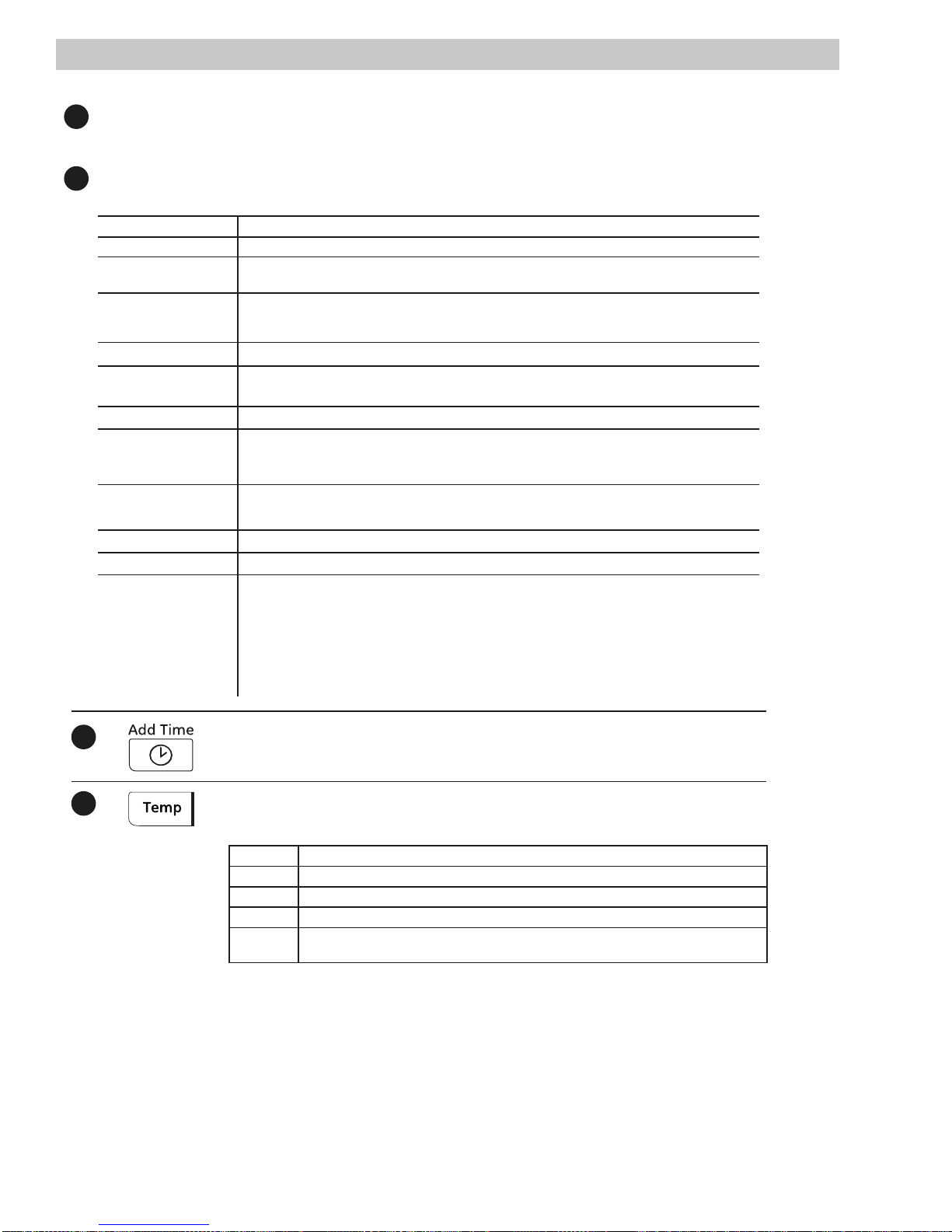
Dry Temp
You can change the temperature of your dry
cycle.
4
High For regular to heavy cottons.
Medium For synthetics, blends and items labeled Permanent Press.
Low For delicates, synthetics and items labeled Tumble Dry Low.
Extra Low For lingerie and special-care fabrics.
No Heat This option may only be used with Air Fluff, in which items are tumbled without
heat.