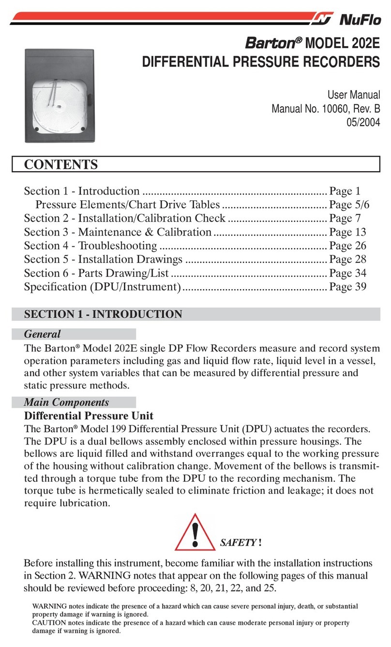
SLOPE INDICATOR GTecLink User manual

GTecLink
Dataloggers
Manual

3
About this document
1. Datalogger Installation 4
4
5
8
1.1 Equipment
1.2 Powering the data logger 1.3
Safely closing the data logger 1.4
Data logger mounting 10
2. Datalogger Configuration 11
12
13
14
2.1 STEP 1: Connect GTecLink Android application 2.2
STEP 2: GTecLink main menu
2.4 STEP 3: Sensor configuration
14
15
15
Vibrating Wire Nodes (526160xx)
GeoFlex Nodes (5780170x)
Analog Node (57804800)
16
16
18
2.5 STEP 4: Sensors Data
2.6 STEP 5: Radio configuration
2.7 STEP 6: Radio signal coverage test 2.8
STEP 7: Test results interpretation 20
3 GTecLink Dataloggers 21
3.1 Vibrating Wire Loggers 21
21
22
22
23
3.1.1 Sensor connection
3.1.2 Barometric measurements
3.1.3 Battery lifespan
3.1.4 Configuration
3.1.5 Data storage 23
3.2 GeoFlex Loggers 24
1
GTecLink Datalogger Manual

24 3.2.1 Sensor Connection
3.2.2 Battery lifespan 26
26
26
a) Geosense / RST IPI
b) Sisgeo IPI
c) MDT Multi-Point-Borehole-Extensometers (MPBX) 27
27
28
3.2.3 Configuration
3.2.4 Data storage
3.3 Analog Logger 29
29
31
34
3.3.1 Sensor Connection
3.3.2 Battery lifespan 3.3.3
Configuration 3.3.4 Data
storage 34
35
4. DATA ACQUISITION
5. CONTACT DGSI 36
2
GTecLink Datalogger Manual

About this document
This user guide explains the basic procedures for data acquisition with the GTecLink family of dataloggers
by DGSI and powered by Loadsensing. Further technical description is available in the datasheets.
The family of GTecLink data loggers by DGSI consists of six different dataloggers that may be used as
standalone data loggers (without remote communication) or radio dataloggers (with remote communication
through a gateway). Please note that we will use the terms datalogger and node interchangeable within this
manual. The models available are:
Data loggers
●52616001 - One Channel VW Datalogger, Polycarbonate
●52616011 - One Channel VW Datalogger, Aluminum
●52616015 - Five Channel VW Datalogger, Aluminum
●57801700 - GeoFlex Datalogger & Enclosed Power Supply
●57801705 - GeoFlex Datalogger
●57804800 - Four Channel Analog Datalogger
3
GTecLink Datalogger Manual

1. DATA LOGGER INSTALLATION
1.1 Equipment
GTecLink dataloggers are shipped with the following accessories:
-Datalogger
-Antenna
-Antenna adapter
-RTC battery (if applicable)
Not included:
-USB-OTG configuration cable
-Batteries
-Sensor surge protection
-Grounding protection
-Mounting supports (if needed)
4
GTecLink Datalogger Manual

1.2 Powering the data logger
The data logger arrives closed and without batteries installed. In order to initialize it, the user should
follow these steps:
a. Openthedatalogger(usinga2.5mmAllenwrench)followingtherecommendedpositions
(Figure 1) in order to avoid damaging the lateral gore valve. The batteries are inserted into the
cover, so be careful not to snap the cable between the cover and the main board.
Figure 1: View of the recommended positions to open the datalogger
b. InserttheRTCbattery(smallbatteryincluded).Firstremovetheupperenclosureofthe battery holder (Figure
2). Polarity is indicated inside the holder.
Figure 2: Removal of the upper enclosure of the battery holder
5
GTecLink Datalogger Manual

The RTC battery keeps time in the data logger regardless of whether or not C-type batteries are also
inserted. The data logger always uses UTC time. However, the data can be visualized in local time in the
gateway or the Android configuration app. RTC battery is only available formultichannel dataloggers.
c. Insert C-type batteries in the battery holders. Between one and fourbatteriescanbe connected.
Polarity is indicated (see Annex 4 for further information on the batteries).
Note
: The device has reverse battery protection but it is not safe to keep batteries reversed in the
datalogger for a long time.
WARNING: RISK OF EXPLOSION IF INCORRECT BATTERIES ARE USED. DISPOSE OF BATTERIES
ACCORDING TO THE INSTRUCTIONS. THIS EQUIPMENT SHOULD BE INSTALLED IN
RESTRICTED ACCESS AREAS.
d. Check thatpowerswitch(SWA,Figure3)isinthecorrectposition.
USB:thedataloggeris powered by the USB cable connected to any Android device
BATT (default): the datalogger is powered by the batteries.
Note
:SomeAndroiddevicescannotpowerthedatalogger,especiallywhenperforming a reading. If
reading fails, set the switch to BATT mode in order to power the datalogger with batteries.
Figure 3: Detail of power switch (SW A)
6
GTecLink Datalogger Manual

1.3 Sensor connection
Sensors are connected to the datalogger at the terminal blocks. Each terminal block corresponds to one
channel of the data logger. The terminal blocks accept wires that are prepared by stripping a short length of
insulation from the end.
Each data logger type has specificinstructionsforsensorwiring.Specificationsforeachmodel can be
found in sections: 3.1. (vibrating wire dataloggers), 3.2. (digital dataloggers) and 3.3. (analog
datalogger).
7
GTecLink Datalogger Manual

1.3 Safely closing the datalogger
This is a very important step to ensure watertightness and durability of the logger. Close the cover by
cross-screwing to the indicated torque 2.5 N.m.
The GTecLink family of data loggers by DGSI have undergone watertightness testing by an external
laboratory and is rated IPX7 (1 meter for 30 minutes) and IPX8 for extended immersion (1 meter for 7 days).
To guarantee watertightness, you must be sure that:
●The box is closed in a cross-shaped order after sensorconnection.Allthescrewsmust first be
inserted and screwed in until they are connected to the box and then adjusted using the torque
wrench. If these steps are not followed, the base faces and cover may be not be parallel, screwing
may become more difficult and the screw threads or the Helicoil inserts may be damaged.
Moreover, the toric joint (seal) may not be properly sealed and the degree of protection against
water intrusion (IP) could not be guaranteed.
●The box is screwed at 2 N.m (for single channel dataloggers) or 2.5 N.m (for multiple
channel dataloggers) using a torque screwdriver (e.g. Ref. 1227107 from WERA).
8
GTecLink Datalogger Manual
1
2
3
4

●The cable glands are closed with a 19 mm open spanner (e.g. Bahco 19 mm Single Ended Open
Spanner; RS Amidata code 717-8992) and the internal nut is held with a 22 mm open spanner (e.g.
Bahco 22 mm Single Ended Open Spanner; RS Amidata code 717-8995).
●A piece of rubber rod to seal the unused cable glands is provided in each box.
●The antenna is mounted. If it is not, the antenna connector should be covered with a cap.
●The sealing ring has not been manipulated either physically or chemically.
●The sealing cap USB connector is coiled.
If any of these conditions are not met, or if one or several components (e.g. gore valve) are damaged,
IPX7 and IPX8 ratings cannot be guaranteed.
Should the datalogger need further sealing due to placement in an extreme environment or in a floodable
manhole, additional sealants will be required to close the box (e.g. Sikaflex products).
Note: Box screws shouldn’t be torqued more than 2.5 N.m, even though they can support a maximum torque of
3.5 N.m. If the torque is exceeded, the Helicoil insert may be damaged. We do not recommend using electric
drills or electric screwdrivers.
9
GTecLink Datalogger Manual

1.4 Datalogger mounting
Dataloggers can be mounted:
●On a wall: mounting brackets are available as additional accessories.
●On a metallic structure: strong magnets are available as additional accessories.
●On a pole: plates for 35 and 50 mm pole diameters are available as additional accessories for this
mounting type.
●Inside a manhole (with a plastic or metallic cover): no special accessories are available for this mounting
type. Even though the dataloggers are IP67 certified, we recommend installing them in holes with
proper drainage so that they won’t be permanently covered with
All GTecLink dataloggers are protected against lightning and there is an easy-to-use
grounding screw (Figure 4) next to the cable glands, which may be connected to provide
protection.
Figure 4: Detail of the grounding screw
Note
:Inordertoprotectthedataloggerfromsurges(especiallyininstallationswithlong cable runs) the
datalogger must be properly grounded via connection to the grounding screw.
10
GTecLink Datalogger Manual

2. DATALOGGER CONFIGURATION
Ideally, this step of the process should be carried out in the same location where the node is going to be
installed. This way, you can perform an on-site radio coverage test.
The node configuration process is done using theGTecLinkapp,whichiscompatible with any Android
device equipped with OTG technology (OS Android HoneyComb 3.1 or higher required). DGSI has
testedSamsung Tab A tablets and Samsung Galaxy 8 phonesandensuresthattheyareabletoconfigure and
test all nodes. (Battery usage may be required as Android devices may not be able to power some sensors.)
The GTecLink app starts up once the device has been connected to the datalogger using the USB-OTG
cable. Manual startup is not necessary.
When a new version of the app is available, the app will display an automatic message.
The whole configuration process doesnottakemorethanfiveminutesand,fromthatmoment, the node
will start taking readings and sending data to the gateway.
11
GTecLink Datalogger Manual

2.1 STEP 1: Connect GTecLink Android application
Download the app onto your Android device from the DGSI website:
https://durhamgeo.com/downloads/android/gteclink.apk
Connect your device to the node using the USB-OTG cable (Accessories list). Make sure the node is
powered on (BATT mode). The app will automatically appear and display the node’s basic information.
12
GTecLink Datalogger Manual

2.2 STEP 2: GTecLink main menu
1) Node info: Basic information about the node (version, ID, temperature, etc.).
2) Sensors data: Access to real time sensor readings and downloaded data storedinthe node.
3) Node Configuration: Access this menu to configure the node.
a) Change node ID: Optional. Change node ID and use a different number.
b) Set date and time.
c) Setup wizard: sensor and radio configuration
4) Factory Reset: This option resets the configurationparametersandremovesallstored data. This
feature is designed to allow the node to be used in different sites. We do not recommend using it
for other purposes unless suggested by DGSI Technical Support.
To access node configuration, go to “Nodeconfiguration” from the main menu and then “Setup Wizard”.
13
GTecLink Datalogger Manual

2.4 STEP 3: Sensor configuration
Sampling rate
Choose the desired reading frequency from the drop-down menu. The highest possible sampling rate is
limited by the network size and vice versa. Smaller networks can read up to every 30 seconds and
frequency is progressively reduced on bigger networks. The app will show the available sampling rates
according to the network size chosen in the previous step.
For more information regarding network size limitations, see the Tables, Number of nodes, Sampling
rate and Slot time chapters in the Gateway User Guide.
Each type of GTecLink datalogger has its own sensor configuration parameters. For more information
about the configuration of each sensor, go to the corresponding datalogger section.
Once the nodes are connected, we strongly recommend setting the sampling rate again from the gateway in
order to optimize the radio configuration of the network.
Vibrating wire nodes
Only activate the channels that are going to be connected to a sensor and choose the sweep frequency
expected for each sensor (according to the sensor data-sheet).
14
GTecLink Datalogger Manual

GeoFlex Nodes
Choose the GeoFlex communicationprotocol amongthe options available. Select Auto Setup. The
resulting reading file will create a column for each address.
Analog Node
This data logger is compatible with seven types of analog sensors: voltage, Full Wheatstone Bridge,
Thermistor, Current loop, potentiometer, DGSI In-Place Inclinometers and PT100.
Choose an interface for each channel and a wiring diagram assistantwillshowup.Choosethe specific
parameters required for each sensor type, such as the Warm up time and Output power supply. Please
note that if DGSI HD IPIs are being read, they must be placed in Channel 1 and the other channels are no
longer available.
15
GTecLink Datalogger Manual

2.5 STEP 4: Sensors Data
The “Sensors data” screen displays the current readings of sensors
connected to the datalogger. Here, you can verify that the sensor is
connected correctlybycheckingifthereadingis consistent.
The node takes anewreadingeverytimetherefreshbuttonis pressed.
Bear in mind that taking a reading might take some time,
particularly when reading RS485 chains of digital sensors.
2.6 STEP 5: Radio configuration
In this step, you select the radio settings.
Enable “Radio” and select the correct region of radio frequency.
For successful communication, the same region must be applied in the
gateway radio configuration.
Enter the network ID and password provided in the Gateway
Information Sheet
. All messages are encrypted with thenetwork
password.
Advanced Options: Default configuration parameters should be suitable
for the majority of networks.
See the Radio specification chapter of the Gateway User Guide or
Annex 01: GTecLink Gateway Radio Specifications v1.8 for more
details on radio models and settings.
Bear in mindthatthe GTecLink appsavesandmaintainsRadiosettings
to simplify configuration of all thenodesinanetwork.Tomodifythesesettings,Radiomustbe enabled
again.
16
GTecLink Datalogger Manual

The network size is the number of nodes (data loggers and GTecLink wireless sensors).We strongly
recommend initially setting it to the final number of nodes that the wireless network will have since this
parameter determines the available sampling rates. Bigger networks do not allow selection of small
sampling rates.
Correct configuration of these two parameters (network size and sensor sampling rate) is crucial to prevent
data transmission collisions, which translates to data loss on the gateway.
For more information, please check the Radio specification chapter in the Gateway User Guide.
17
GTecLink Datalogger Manual

2.7 STEP 6: Radio signal coverage test
This is the final step in node configuration. The app performs
a signal coverage test to check the quality of
communication with the gateway. The gateway must have been
previously connected and configured.
This test will check for correct connectivity between the datalogger
and the gateway. The datalogger will send some test packages.
The Android app will then check on the gateway (using the
Internet connection) for the reception of these packets. Hence,
the test will check for:
●Correct gateway operation and communication.
●Correct radio configuration of both the gateway and
data logger (including matching region and ID/
password configurations).
●Quality of the signalreceivedbythegatewayfrom the
data logger.
By clicking the “Next” button, GTecLink will run an Onlinetest. For the results of this test to be
immediately displayed on the Android device, the gateway and the Android device must also be connected
to the Internet.
In order to perform an online test, the gateway serial number and remote access password must be
provided totheapp.Theremoteaccesspasswordisusedtoprotectthegatewayfrom
access via the local network or the Internet. It can be different than the radio network password even
though it’s set to the same value by default (credentials at Gateway Information Sheet
).
When doing the Radio signal coverage test, the position of the Android device is saved
(ifyou gave the app permission to access the GPS data) and a security token number identifies each
test. If the gateway and/or the Android device are not connected to the Internet during the test, the
onlinetestwillfailandyouwillneedtoperforman“Offlinetest”.Inthismode,however,the results of the
test cannot be displayed on the Android device. The security token number identifies each test. Write
down the token
numberalongwithadescriptionofwhereandunder what conditions the test was taken. Check the results
of the coverage test on the gateway web interface (under Network→Signal coverage test map → Download
all tests of this network).
18
GTecLink Datalogger Manual

If the Android does not have an active Internet connection, then the test must be run offline. Click on “Offline
test”. A CSV file with the test results can be downloaded from the gateway web interface.
Radio signal coverage performed at the end of the datalogger setup (using the Setup wizard).
19
GTecLink Datalogger Manual
Table of contents
Popular Data Logger manuals by other brands

Lambrecht
Lambrecht TROPOS-124 operating instructions
Hioki
Hioki LR5092-20 instruction manual
Davis Instruments
Davis Instruments WeatherLink 6510USB Getting started guide
TiTLEY Scientific
TiTLEY Scientific CHORUS user manual

Loggerflex
Loggerflex bun hydro user manual

MadgeTech
MadgeTech Titan S8 Product user guide
