SLS Audio CS1090 User manual

SLS CS1090 Speaker
User’s Guide
Issue 2 11/15/2018
Part Number 9112433
™

ii SLS™ CS1090 Speaker User’s Guide
SLS Audio
A Division of Dolby Laboratories
Headquarters
SLSAudio
1650WestJacksonStreet
Ozark,Missouri65721USA
Telephone417‐883‐4589
Fax417‐485‐5606
www.slsaudio.com
DOLBYLABORATORIES,INC.WARRANTS,TOTHEORIGINALPURCHASERONLY,THATTHISPRODUCTWILLBEFREEFROMDEFECTSIN
MATERIALSANDWORKMANSHIPUNDERNORMALUSEFORTHEGREATEROF1YEAR,ORTHEMINIMUMPERIODREQUIREDUNDER
LOCALLAW,COMMENCINGUPONTHEDATEOFORIGINALRETAILPURCHASE.THISLIMITEDWARRANTYISNON‐TRANSFERABLE.
THISLIMITEDWARRANTYDOESNOTCOVERDAMAGEORMALFUNCTIONSCAUSEDBYAC
ENT,DISASTER,MISUSE(INCLUDINGANYUSEINAMANNERCONTRARYTOTHEINSTRUCTIONSCONTAINEDINANYUSERGUIDEOR
ONTHEPACKAGINGOFTHEPRODUCT),ABUSE,NEGLIGENCEOROTHEREXTERNALCAUSES;POWERSURGES;IMPROPER
INSTALLATION;THIRD‐PARTYPRODUCTS;UNAUTHORIZEDOPENING,USE,SERVICE,TAMPERING,ALTERATION,REPAIROR
MODIFICATION;ORINADEQUATEPACKINGORSHIPPINGPROCEDURES.THISLIMITEDWARRANTYALSODOESNOTCOVERCOSMETIC
DAMAGEORISSUESINCIDENTTONORMALWEARANDTEAR.
DISCLAIMEROFWARRANTIES
THEREARENOOTHEREXPRESSORIMPLIEDWARRANTIESANDNOWARRANTYOFMERCHANTABILITYORFITNESSFORAPARTICULAR
PURPOSE,OROFNONINFRINGEMENTOFTHIRD‐PARTYRIGHTS(INCLUDING,BUTNOTLIMITEDTO,COPYRIGHTANDPATENTRIGHTS).
LIMITATION
OF
LIABILITY
ITISUNDERSTOODANDAGREEDTHATDOLBYLABORATORIES’LIABILITY,WHETHERINCONTRACT,INTORT,UNDERANYWARRANTY,
INNEGLIGENCE,OROTHERWISE,SHALLNOTEXCEEDTHECOSTOFREPAIRORREPLACEMENTOFTHEDEFECTIVECOMPONENTSOR
ACCUSEDINFRINGINGDEVICES,ANDUNDERNOCIRCUMSTANCESSHALLDOLBYLABORATORIESBELIABLEFORINCIDENTAL,
SPECIAL,DIRECT,INDIRECT,ORCONSEQUENTIALDAMAGES(INCLUDING,BUTNOTLIMITEDTO,DAMAGETOSOFTWAREOR
RECORDEDAUDIOORVISUALMATERIAL),COSTOFDEFENSE,ORLOSSOFUSE,REVENUE,ORPROFIT,EVENIFDOLBYLABORATORIESOR
ITSAGENTSHAVEBEENADVISED,ORALLYORINWRITING,OFTHEPOSSIBILITYOFSUCHDAMAGES.
WARRANTYCLAIMS
WARRANTYPERIOD.ACINEMASUPPORTREPRESENTATIVEWILLDETERMINEWHETHERTHEPURPORTEDDEFECTISCOVEREDUNDER
THEWARRANTY.IFCOVERED,[email protected]WILLPROVIDEYOUWITHDETAILEDINFORMATIONONHOWANDWHERE
TOSENDYOURDEFECTIVEPRODUCT.FAILURETOFOLLOWTHEREPAIRRETURNINSTRUCTIONSMAYVOIDYOURWARRANTY.
PRODUCTMODEL:
THISDOCUMENTATIONAPPLIESTOMODELCID1012.
PATENTS:
THISPRODUCTMAYBEPROTECTEDBYPATENTSANDPENDINGPATENTAPPLICATIONSINTHEUNITEDSTATESANDELSEWHERE. FOR
MOREINFORMATION,INCLUDINGASPECIFICLISTOFPATENTSPROTECTINGTHISPRODUCT,PLEASEVISIT
http://www.dolby.com/patents.
.
DolbyandDolbyAtmosareregisteredtrademarksofDolbyLaboratories.
SLSandtheSLSAudiologoaretrademarksofDolbyLaboratories.
Allothertrademarksremainthepropertyoftheirrespectiveowners.
©DolbyLaboratories2018Allrightsreserved.
PartNumber9112433
Issue2

Regulatory Notices
SLS™ CS1090 Speaker User’s Guide iii
IMPORTANT SAFETY INSTRUCTIONS
1. USERASSUMESALLRESPONSIBILITYANDLIABILITYFORTHE
INSTALLATIONOFTHISPRODUCT.
2. Priortoinstallingthisproduct,readandcompletelyunderstandtheinstallation
instructions.Youmustreadtheseinstructionstopreventpersonalinjuryand
propertydamage.Keeptheinstallationinstructionsinaneasilyaccessiblelocationfor
futurereference.
3. Installationmustbeperformedbyqualified,licensed,andinsuredinstallers,and
installedinaccordancewithalllaws,rules,andregulationsapplicabletothe
installationsite.Failuretodosocouldresultinseriouspersonalinjuryorevendeath.
Consultaninstallationprofessionaliftheinstallationinstructionsarenotunderstood.
4. Compliancewithlocalbuildingcodes(and,whereapplicable,nationalcodes)isthe
responsibilityofthebuyerand/orinstaller.Usersshouldconsultwithlocalregulatory
authoritiesforspecificcodesand/orguidelinesfortheuseofthisproduct.
5. Useproperpersonalliftingtechniqueswhenworkingwithheavyobjectstoavoid
personalinjury.
6. Anysuppliedrigginghardwareisintendedonlyforusewiththespecified
loudspeaker.Theuserassumesallriskoflossand/orinjuryarisingoutoftheuseof
thesuppliedrigginghardwarewithanyotherloudspeaker.
7. Thisguideismeantonlyforthepurposeofinstructingtheuserintheintendeduseof
SLSsuppliedrigging.Allotherriggingisconsideredpartofthevenueand/oruser
suppliedequipmentandisnotaddressedinthisguide.”
8. Thisguideisnotacomprehensivesourceforriggingingeneral.Userassumesall
responsibilityforensuringthatacceptedriggingandsafetypracticesareemployed.
UserassumesallresponsibilityfortheappropriateuseofSLSsuppliedrigging
hardwareandfollowsataminimumallapplicablelaws,rules,andregulationsin
forceforeachvenue.
9. Forceilinginstallations,thesystemsafetycablemustbemountedtothestructural
steelabovethesuspendedceilingtileinanauditorium.Donotattachthesystem
safetycabletoanywoodstructure,woodroofjoists,orwoodframe.Forwall
installations,thesystemsafetycablemustbeanchoredtothebuildingstructure
independentoftheprimaryriggingdevice.Inallinstances,thesafetycablemustbe
mountedinawaythatsupportsaminimumof5timesthestaticweightofthe
speaker,orgreaterifahigherrequirementismandatedasperlocallaws.
10. Donotinstallonastructurethatispronetoabnormalvibration,movement,orchance
ofimpact.Failuretodosocouldresultindamagetotheequipmentand/ordamageto
themountingsurface.
11. Makesurethatnowaterpipes,naturalgaslines,electricalwire,orconduitarepresent
wherethespeakeristobeinstalled.Cuttingordrillingintowaterpipes,naturalgas
lines,electricalwire,orconduitcouldcauseseriouspersonalinjuryorproperty
damage.
12. Priortoinstallation,alwaysinspectallhardwarecomponentsforwear,deformations,
corrosion,andmissingordamagedparts.
13. Thisproductisintendedforinstallationindryindoorlocationsonly.Premature
productfailureorseriouspersonalinjurycouldoccurifthisproductisusedoutdoors
orinwetindoorenvironments.
14. Noopenflamesourcesshouldbeplacedontheapparatus.

iv SLS™ CS1090 Speaker User’s Guide
Regulatory Notices
15. Noinformationcontainedinthisguideisintendedasawarrantyonthepartof
SLS.
Anyoneusingthisinformationassumesallliabilityarisingfromitsuse.Productabuse,
useoftheproductnotinaccordancewithSLSinstructions,oruseinanapplicationfor
whichtheproducthasnotbeendesignedisnotcoveredunderanySLSwarranty,noris
SLSliableforanylossordamage.
16. THISAPPARATUSISNOTINTENDEDFORFLOOR‐STANDINGINSTALLATIONS
WITHNOANCHORAGE.

SLS™ CS1090 Speaker User’s Guide v
Table of Contents
Chapter 1 Introduction ..................................................................................................1
1.1 CS1090 Overview...............................................................................................................1
1.2 Customer Support and Spare Parts ...................................................................................2
Chapter 2 Installing the CS1090...................................................................................3
2.1 Installing the CS1090 Using the YK-1090 in 5.1 and 7.1 Auditoriums................................3
2.1.1 Tools Required.........................................................................................................3
2.1.2 Identifying the YK-1090 Rigging Kit Parts................................................................3
2.1.3 Installing the CS1090 in a 5.1 or 7.1 Sidewall Configuration ...................................4
2.1.4 Connecting the Safety Cable ...................................................................................6
2.1.5 Connecting Audio.....................................................................................................6
2.2 Installing the CS1090 Using the YK-1090 and MMA-1090 in Dolby Atmos Auditoriums....7
2.2.1 Tools Required.........................................................................................................7
2.2.2 Identifying the MMA-1090 Rigging Kit Parts ............................................................8
2.2.3 Installing the CS1090 in a Dolby Atmos Overhead Configuration ...........................8
2.2.4 Connecting the Safety Cable .................................................................................11
2.2.5 Connecting Audio...................................................................................................12
2.2.6 Installing the CS1090 in a Dolby Atmos Sidewall Configuration............................12
2.2.7 Connecting the Safety Cable .................................................................................15
2.2.8 Connecting Audio...................................................................................................15
2.3 Dimensions.......................................................................................................................16


SLS™ CS1090 Speaker User’s Guide 1
Chapter 1
Introduction
1.1 CS1090 Overview
TheSLS™CS1090isahigh‐performancecinemasurroundloudspeakerforusein5.1and
7.1cinemaauditoriumsandsmalltomediumsizedDolbyAtmos®equippedauditoriums.
Thesespeakersshipinpairs.
TwooptionalriggingkitsareavailablefortheCS1090:
•YK‐1090kit(enablesonlytiltadjustmentsforside‐wallinstallations):
•Thiskitincludesyokesforuseinallauditoriums,shouldereyebolts,andother
hardware.
•Adedicated1/4”‐20sizedinsertisprovidedoneachspeakerforusewiththe
providedeyebolts(orinstaller‐suppliedeyebolts)toattachasafetycable.
• MMA‐1090kit(forDolbyAtmosinstallations).
•Thisadd‐onkittotheYK‐1090kitenablesthree‐axisadjustmentsforceiling
installationsandtwo‐axisadjustmentsforside‐wallinstallations.Itincludes
U‐brackets,screws,andotherhardware.
•YoucanalsousetheMMA‐1090riggingkitwiththeFCT‐24flat‐mountorRCT‐24
recessed‐mountceilingtileriggingkitstoenabletheCS1090toflyfromtheceiling
tilegrid.However,theRCT‐24mayrestricttheavailableangle.Detailed
documentationontheseceilingtileinstallationsisprovidedintheSLSCeilingTile
RiggingKitsInstallationGuide,whichisavailablefordownloadat
https://www.dolbycustomer.com.
Forthird‐partyhardwarerigginginstallations,four1/4ʺ‐20sizedaachmentpointsina
standardizedlayoutonthebackoftheCS1090areavailable.Thefourboltsthatarealready
installedinthesepositionsoneachspeakermaybereusedforfasteningthethird‐party
hardwaretotheCS1090.
1.2 CS1090 Specifications
FollowingaretheCS1090generalspecifications:*
•Frequencyresponse:55Hzto20kHz
•Sensitivity:1watt@1M:94dB
• Continuouspowerrating:300watts
•MaximumcontinuousratedSPLat1meter:119dB
•Coverageangle:90degreeshorizontal,60degreesvertical
•Drivers:10‐inchlow‐frequency,1‐inchcompressiondriverhigh‐frequency
•Size:
•W
idth:15.48inches(393millimeters)
•Height:18.5inches(470millimeters)
•Topdepth:11inches(280millimeters)
• Bottomdepth:6.2inches(157millimeters)

2SLS™ CS1090 Speaker User’s Guide
Introduction
•Netweight:28pounds(12.7kilograms)
*Duetoproductimprovementresearch,SLSAudioreservestherighttomakechangesto
existingproductswithoutnotice.
1.2 Customer Support and Spare Parts
IfyouneedassistanceinstallingtheCS1090,requirereplacementparts,orhaveother
questions,youcancontactusat:
Portal:www.dolbycustomer.com
Email:[email protected]
Region SupportPhoneNumbers
Americas +1‐415‐645‐4900
EMEA +44‐33‐0808‐7700
APAC +86‐400‐692‐6780
Japan +81‐3‐4540‐6782

SLS™ CS1090 Speaker User’s Guide 3
Chapter 2
Installing the CS1090
2.1 Installing the CS1090 Using the YK-1090 in 5.1 and 7.1
Auditoriums
YoucanusetheYK‐1090riggingkitfor5.1and7.1auditoriumsidewallmounting
installations(whereonlythetiltaxisneedstobeadjusted).
2.1.1 Tools Required
•7/32‐inchAllenwrenchwrenchtoremovetheboltsforinstallationoftheYK‐1090
•#2Phillipsscrewdriverforattachingspeakerwiretobarrierstrip
2.1.2 Identifying the YK-1090 Rigging Kit Parts
ThefollowingpartsareincludedintheYK‐1090riggingkit:
•Twoyokes
•Fourneoprenewashers
•Two¼”‐20closedshouldereyebolts(notshown;attachdirectlytoeachCS1090)
Warning: TOPREVENTINJURY,THISAPPARATUSMUSTBESECURELYATTACHED
TOTHEFLOOR/WALLINACCORDANCEWITHTHEINSTALLATION
INSTRUCTIONS.CONSULTAPROFESSIONALMECHANICALOR
STRUCTURALENGINEERTOOBTAINAPPROVALFORALL
ATTACHMENTSTOTHESTRUCTURE.THISAPPARATUSMUSTBE
INSTALLEDBYLICENSEDPROFESSIONALINSTALLERS.IFNOT
ATTACHEDTOTHESTRUCTUREPROPERLY,THISAPPARATUSCOULD
FALLANDCAUSEPERSONALINJURYORDEATH.INSPECTALL
COMPONENTSBEFOREINSTALLATION.THISAPPARATUSISNOT
INTENDEDFORFLOORSTANDINGINSTALLATIONSWITHNO
ANCHORAGE.ALLLOCALBUILDINGANDSEISMICCODESMUSTBE
ADHEREDTO.
4SLS™ CS1090 Speaker User’s Guide
Installing the CS1090
Figure2‐1
Figure 2-1 YK-1090 Rigging Kit Parts
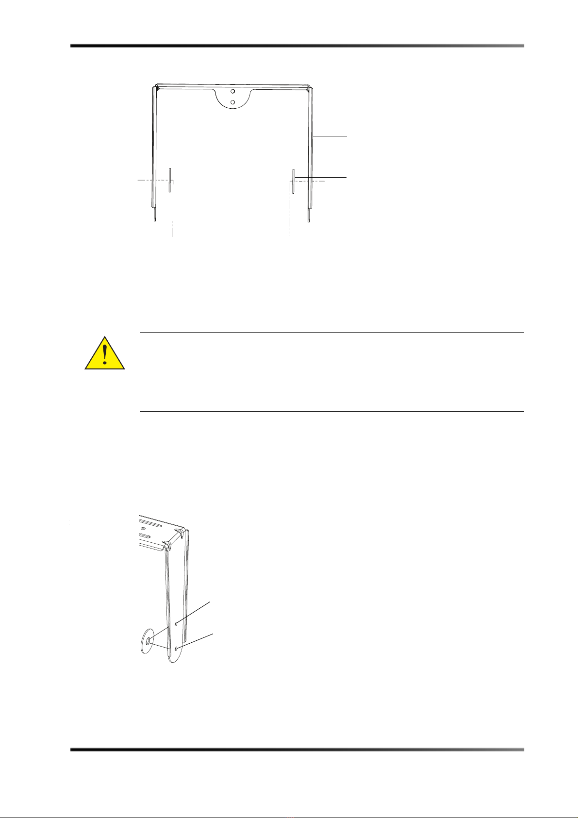
2.1.3 Installing the CS1090 in a 5.1 or 7.1 Sidewall Configuration
ToinstalltheCS1090,therearetwoyokeattachmentoptions:
•Ifmaximumadjustmentonthetiltaxisisneeded,youneedtomounttheCS1090to
theattachmentpointsthatarefarthestfromthewall.
•Ifthemaximumadjustmentisnotrequired,werecommendthatyoumountthe
CS1090totheattachmentpointsclosetothewalltoavoidobstructinglineofsightto
thescreen.
Figure2‐2
Figure 2-2 Yoke Placement Options
Warning: USETHEAPPROPRIATEQUANTITYOFM10OR3/8‐INCHBOLTSTO
SECURETHEHARDWARETOTHESTRUCTURE.BASEDONTHEWEIGHTOF
THEAPPARATUS,INSTALLER‐SUPPLIEDHARDWAREMUSTHAVEA
MINIMUM5:1SAFETYFACTORORGREATERIFAHIGHER
REQUIREMENTISMANDATEDASPERLOCALLAWS.HARDWAREMUST
BESECURELYTIGHTENED.
1 of 2 yokes
1 of 4 washers
CS1090 mounting position
for minimum obstruction
for line of sight to screen
CS1090 mounting position
for maximum vertical angle
adjustment

Installing the CS1090 Using the YK-1090 in 5.1 and 7.1 Auditoriums
SLS™ CS1090 Speaker User’s Guide 5
1. Removethe¼”‐20bolt,andinsertandinstalltheprovided¼”‐20shouldereyebolt(or
aninstaller‐suppliedeyebolt)atthebackoftheCS1090.
Figure2‐3
Figure 2-3 Eyebolt in Place for Safety Cable
ToinstalltheCS1090:
1. Mounttheyoketothewallwithinstaller‐suppliedhardwareusingaminimumof
fourfasteners.WerecommendM10or3/8”sizedbolts.
2. Remove the two3/8”‐16boltsfromthesidesoftheCS1090.
3. Peeloffthepaperontheneoprenewasherstoexposetheadhesivelayer,andadhere
thewasherstotheyokeinthedesiredyokepositionholes.
4. PositiontheCS1090betweentheyoke,andinsertthetwo3/8‐”16boltsandlightly
tighten.
5. Adjustthetiltangleasneeded,andsecurelytightentheboltstocompletethe
installation.
Figure2‐4
Figure 2-4 CS1090 Placement

6SLS™ CS1090 Speaker User’s Guide
Installing the CS1090
2.1.4 Connecting the Safety Cable
AftertheCS1090isattachedtothestructure,youmustconnectasecondarysafety
attachmentpointtoanindependentpointonthebuildingstructure.The1/4”‐20eyeboltis
providedtoattachaninstaller‐suppliedsafetycable.BasedontheweightoftheCS1090,all
installer‐suppliedsafetyrigginghardwaremusthaveaminimum5:1safetyfactoror
greaterifahigherrequirementismandatedasperlocallaws.Removeallslacktoavoidany
shockloadingofthecableintheeventofaprimaryriggingfailure.
2.1.5 Connecting Audio
Theinputbarrierstripaccepts16‐to12gaugewire,eitherwith#6spadelugsorbarewire.
Alwaysuseindustrystandardpracticesforselectingwiregauge,basedontheproduct
powerratingandcablelength.Notethatthebarrierstripismarkedwithaplus(+)orred
indicatortoshowthepolarity.PerIECstandard,apositivevoltageonthepositivemarked
inputresultsinthelow‐frequencydriversmovingoutward.Alwaystiedownthecableto
availablehardwaretominimizeanybuzzingorpullouts.
Warning: INSTALLER‐SUPPLIEDRIGGINGHARDWAREMUSTHAVEAMINIMUM
5:1SAFETYFACTORBASEDONTHEWEIGHTOFTHEAPPARATUS.YOU
MUSTSECURELYTIGHTENTHEHARDWARE.DONOTSECURETHE
SAFETYCABLEBACKTOTHEYOKE.REMOVEALLSLACKFROMTHE
CABLE.REPLACETHECABLEIFITHASBEENPULLEDINTHEEVENTOF
APRIMARYRIGGINGFAILURE.
Warning: TURNOFFALLAMPLIFIERSWHENCONNECTINGTHELOUDSPEAKER
WIRING.

Installing the CS1090 Using the YK-1090 and MMA-1090 in Dolby Atmos Auditoriums
SLS™ CS1090 Speaker User’s Guide 7
2.2 Installing the CS1090 Using the YK-1090 and MMA-1090 in
Dolby Atmos Auditoriums
TheMMA‐1090riggingkitisanadd‐ontotheYK‐1090riggingkit.Youneedbothofthese
kitstomountthespeakersinDolbyAtmosauditoriums,wherebothverticaland
horizontalaxisadjustmentisrequired.Inadditiontotheyokes,neoprenewashers,and
eyeboltsthatareincludedwiththeYK‐1090kit,youneedadditionalhardwarethatis
includedintheMMA‐1090kitforoverheadinstallations.
2.2.1 Tools Required
•7/32‐inchAllenwrenchwrenchorsocket
•#2Phillipsscrewdriverforattachingspeakerwiretobarrierstrip
•9/16‐inchendwrenchorsocket
Note: TheCS1090providesafrontbafflethatistilted15degreesrelativetoanoverallbox
tiltof0degrees.WhenusingtheDolbyAudioRoomDesignTool(DARDT)
specificationforaiminganglecalculationsinDolbyAtmosinstallations,subtract
15degreesfromthedownangledataprovidedforsidesurrounds.Foroverheads,
subtract15degreesfromtheaxisthatthefrontbaffleslopeisangledtoward.
Warning: TOPREVENTINJURY,THISAPPARATUSMUSTBESECURELYATTACHED
TOTHEFLOOR/WALLINACCORDANCEWITHTHEINSTALLATION
INSTRUCTIONS.CONSULTAPROFESSIONALMECHANICALOR
STRUCTURALENGINEERTOOBTAINAPPROVALFORALL
ATTACHMENTSTOTHESTRUCTURE.THISAPPARATUSMUSTBE
INSTALLEDBYLICENSEDPROFESSIONALINSTALLERS.IFNOT
ATTACHEDTOTHESTRUCTUREPROPERLY,THISAPPARATUSCOULD
FALLANDCAUSEPERSONALINJURYORDEATH.INSPECTALL
COMPONENTSBEFOREINSTALLATION.THISAPPARATUSISNOT
INTENDEDFORFLOORSTANDINGINSTALLATIONSWITHNO
ANCHORAGE.ALLLOCALBUILDINGANDSEISMICCODESMUSTBE
ADHEREDTO.
8SLS™ CS1090 Speaker User’s Guide
Installing the CS1090
2.2.2 Identifying the MMA-1090 Rigging Kit Parts
ThefollowingpartsareincludedintheMMA‐1090riggingkit:
•TwoU‐brackets
•Six3/8‐inchnylonlocknuts
•Twelve1‐inchwashers
•Six3/8ʺ‐16sizedscrews
Figure2‐5
Figure 2-5 MMA-1090 Rigging Kit Parts
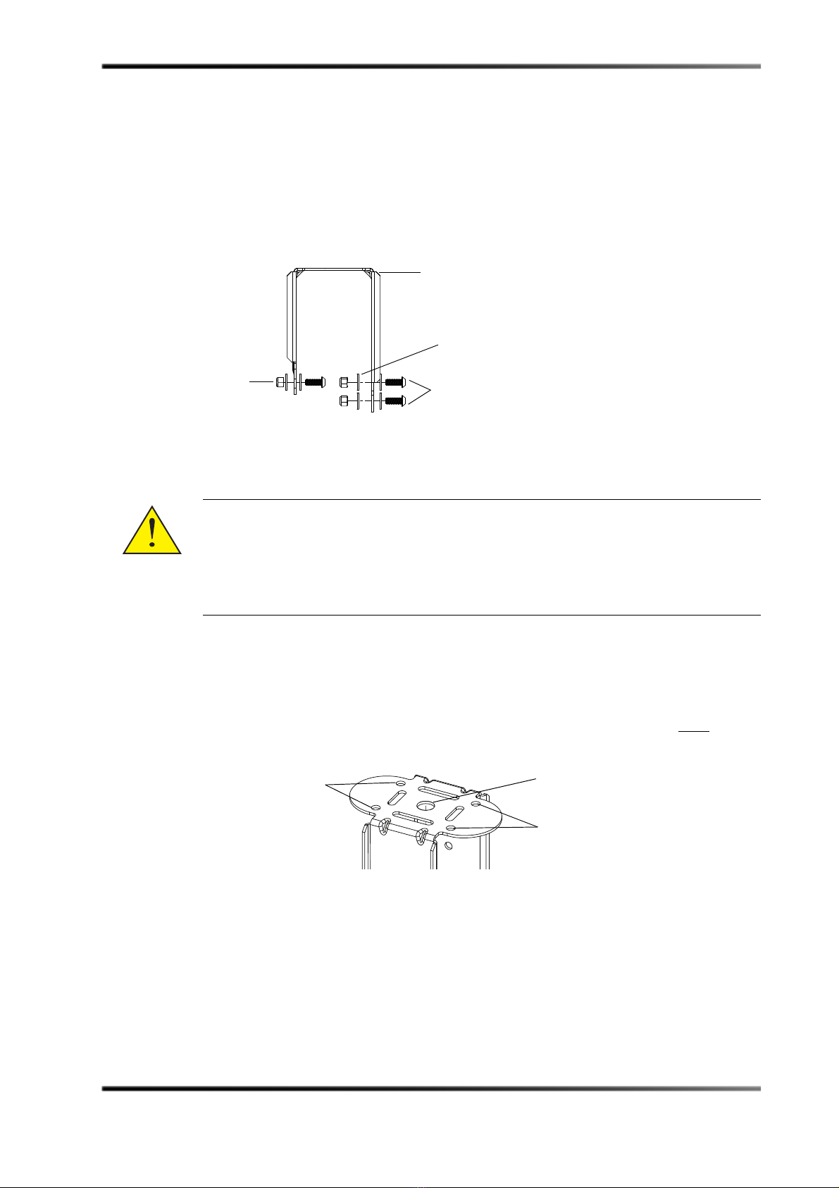
2.2.3 Installing the CS1090 in a Dolby Atmos Overhead Configuration
ToinstalltheCS1090:
1. AttachtheU‐brackettothestructureusinginstaller‐suppliedhardware.
YoucanutilizeanyoftheattachmentpointsonthebackoftheU‐bracket.Ifthree‐axis
aiming(vertical,horizontal,rotational)isrequired,useonlythesingle‐center
attachmentpoint.IftheU‐bracketisattacheddirectlytotheceiling,youmustuseall
fourpointsfortwo‐axisaiming.
Figure2‐6
Figure 2-6 Multiple Attachment Points
Warning: USETHEAPPROPRIATEQUANTITYOFM10OR3/8‐INCHBOLTSTO
SECURETHEHARDWARETOTHESTRUCTURE.BASEDONTHEWEIGHTOF
THEAPPARATUS,INSTALLER‐SUPPLIEDHARDWAREMUSTHAVEA
MINIMUM5:1SAFETYFACTORORGREATERIFAHIGHER
REQUIREMENTISMANDATEDASPERLOCALLAWS.HARDWAREMUST
BESECURELYTIGHTENED.
1 of 2 U-brackets
2 of 6 screws
1 of 12 washers
1 of 6
lock nuts
Center-single attachment
point for three-axis aiming
Other attachment points
for two-axis aiming
Other attachment points
for two-axis aiming

Installing the CS1090 Using the YK-1090 and MMA-1090 in Dolby Atmos Auditoriums
SLS™ CS1090 Speaker User’s Guide 9
ToallowtheCS1090tohangfromtheceilingtilegrid,youcanusetheMMA‐1090
riggingkitwiththeFCT‐24flat‐mountorRCT‐24recessed‐mountceilingtilerigging
kits.However,theRCT‐24mayrestricttheavailableangle.YouinserttheM20hollow
boltfromtheceilingtilekits,asshowninthefollowingfigure(FCT‐24shownin
figure).
Figure2‐7
Figure 2-7 MMA-1090 with FCT-24 or RCT-34 Rigging Kit
FordetailedinformationonFCT‐24andRCT‐24ceilingtileinstallations,youcan
downloadtheSLSCeilingTileRiggingKitsInstallationGuideat
https://www.dolbycustomer.com.
2. Removethetwo3/8”‐16boltsfromthesidesoftheCS1090,placethespeakerintothe
yoke,thenpositiontheneoprenewasherbetweenthespeakerandyoke,andreinstall
thebolts.
Figure2‐8
Figure 2-8 Neoprene Washer Positions
Steel washer
Neoprene washer (x3)
CS1090 mounting position
for minimum obstruction
for line of sight to screen
CS1090 mounting position
for maximum vertical angle
adjustment

10 SLS™ CS1090 Speaker User’s Guide
Installing the CS1090
3. Removethe¼”‐20bolt,andinsertandinstalltheprovided¼”‐20shouldereyebolt(or
aninstaller‐suppliedeyebolt)atthebackoftheCS1090.Aneyeboltisprovidedwith
theYK‐1090riggingkit.
Figure2‐9
Figure 2-9 Eyebolt in Place for Safety Cable
4. AttachtheU‐brackettotheyoke,asshowninthefollowingfigure,thenadjustanyof
theanglesasneeded,andtightendownallbolts.
Figure2‐10
Figure 2-10 Attach Yoke to U-bracket

Installing the CS1090 Using the YK-1090 and MMA-1090 in Dolby Atmos Auditoriums
SLS™ CS1090 Speaker User’s Guide 11
TheU‐bracketalsoprovidestwooptionsforattachmenttotheyoke:
•Formaximumverticalandhorizontalangleadjustment,usetheholesontheyokeand
U‐bracket,asshowninFigure 2‐11.
•Incaseswhereminimalverticalorhorizontalangleadjustmentisneeded,usethe
holesontheyokeandU‐bracketshowninFigure 2‐12toavoidblockingtheimage
projectedtothescreen.
Youcanalsouseacombinationofbothoftheseexamples.
Figure2‐11
Figure 2-11 Attachment Points for Maximum Vertical and Horizontal Angle Adjustment
Figure2‐12
Figure 2-12 Attachment Points for Improved Sight Lines to Minimize Projector Light-Beam Blockage
2.2.4 Connecting the Safety Cable
AftertheCS1090isattachedtothestructure,youmustconnectasecondarysafety
attachmentpointtoanindependentpointonthebuildingstructure.The1/4”‐20eyebolt
isprovidedtoattachaninstaller‐suppliedsafetycable.Basedontheweightofthe
CS1090,allinstaller‐suppliedsafetyrigginghardwaremusthaveaminimum5:1safety
factororgreaterifahigherrequirementismandatedasperlocallaws.Removeallslack
toavoidanyshockloadingofthecableintheeventofaprimaryriggingfailure.
Warning: INSTALLER‐SUPPLIEDRIGGINGHARDWAREMUSTHAVEAMINIMUM
5:1SAFETYFACTORBASEDONTHEWEIGHTOFTHEAPPARATUS.YOU
MUSTSECURELYTIGHTENTHEHARDWARE.DONOTSECURETHE
SAFETYCABLEBACKTOTHEYOKE.REMOVEALLSLACKFROMTHE
CABLE.REPLACETHECABLEIFITHASBEENPULLEDINTHEEVENTOF
APRIMARYRIGGINGFAILURE.
U-bracket
Use lower holes
U-bracket
Use upper holes

12 SLS™ CS1090 Speaker User’s Guide
Installing the CS1090
2.2.5 Connecting Audio
Theinputbarrierstripaccepts16‐to12gaugewire,eitherwith#6spadelugsorbarewire.
Alwaysuseindustrystandardpracticesforselectingwiregauge,basedontheproduct
powerratingandcablelength.Notethatthebarrierstripismarkedwithaplus(+)orred
indicatortoshowthepolarity.PerIECstandard,apositivevoltageonthepositivemarked
inputresultsinthelow‐frequencydriversmovingoutward.Alwaystiedownthecableto
availablehardwaretominimizeanybuzzingorpullouts.
2.2.6 Installing the CS1090 in a Dolby Atmos Sidewall Configuration
Toinstallinasidewallconfiguration:
1. AttachtheU‐brackettothewallwithuser‐suppliedhardwareusingtheholesand
orientation,asshowninFigure 2‐13.Werequirethatyouuseaminimumoffour
fasteners.WerecommendM10or3/8”bolts.
Figure2‐13
Figure 2-13 Four Side-Wall Mounting Attachment Points (and Required Orientation)
2. Removethetwo3/8”‐16boltsfromthesideoftheCS1090,andplacethespeakerinto
theyoke.
Warning: TURNOFFALLAMPLIFIERSWHENCONNECTINGTHELOUDSPEAKER
WIRING.
Warning: USETHEAPPROPRIATEQUANTITYOFM10OR3/8”BOLTSTOSECURE
THEHARDWARETOTHESTRUCTURE.BASEDONTHEWEIGHTOFTHE
APPARATUS,INSTALLER‐SUPPLIEDHARDWAREMUSTHAVEA
MINIMUM5:1SAFETYFACTORORGREATERIFAHIGHER
REQUIREMENTISMANDATEDASPERLOCALLAWS.HARDWAREMUST
BESECURELYTIGHTENED.
Side-wall attachment points
Side-wall attachment points

Installing the CS1090 Using the YK-1090 and MMA-1090 in Dolby Atmos Auditoriums
SLS™ CS1090 Speaker User’s Guide 13
3. Positiontheneoprenewasherinbetweenthespeakerandyoke(usingtheadhesiveon
thewashertoadheretotheyokeatthedesiredposition),andthenreinstallthebolts.
Figure2‐14
Figure 2-14 Neoprene Washer Position
4. Removethe¼”‐20bolt,andinsertandinstalltheprovided¼”‐20shouldereyebolt(or
aninstaller‐suppliedeyebolt)atthebackoftheCS1090.Aneyeboltisprovidedwith
theYK‐1090riggingkit.
Figure2‐15
Figure 2-15 Eyebolt in Place for Safety Cable
5. ConnecttheU‐brackettotheyoke,asshowninFigure 2‐16.
Figure2‐16
Figure 2-16 Connecting the U-Bracket to the Yoke
CS1090 mounting position
for minimum obstruction
for line of sight to screen
CS1090 mounting position
for maximum vertical angle
adjustment

14 SLS™ CS1090 Speaker User’s Guide
Installing the CS1090
6. Adjusttheanglesasneeded,andtightendownallbolts.
TheU‐bracketalsoprovidestwooptionsforattachingtheyoke:
•Formaximumverticalandhorizontalangleadjustments,usetheholesontheyoke
andU‐bracket,asshowninFigure 2‐17.
•Incaseswhereminimalverticalorhorizontalangleadjustmentisneeded,usethe
holesasshowninFigure 2‐18topreventtheblockingofanylinesofsighttothe
screen.Youcanalsocombinebothoftheseapproaches.
Figure2‐17
Figure 2-17 Attachment Points for Maximum Vertical and Horizontal Angle Adjustment (Top View)
Figure2‐18
Figure 2-18 Attachment Points for Improved Sight Lines (Top View)
Use lower holes
U-bracket
U-bracket Use upper holes
Table of contents
Other SLS Audio Speakers manuals


