SLX 27868HS User manual

Features
❏LED level indicator
❏Sensitive meter for in-line use.
❏Built-in amplier compensates for insertion loss
❏Pocket size and lightweight
Specications
Frequency Range (MHz) Terrestrial 40~862
SAT 950~2250
Insertion Loss (dB) 3dB Sat, 6dB TV
Return Loss Input (dB) 8
Output (dB) 8
Input Level Terrestrial (dBμV) 50-80
SAT (dBμV) 70-100
Power Requirement 15V DC @ 40mA
Battery used (For DVB-T Only) PP3 9V
Sensitivity Control
Satellite/DVB-T
Switch
Signal Strength
LEDs Power LED
Satellite/Aerial Digital TV Signal Meter
USER GUIDE
27868HS
Customer Careline: 08457 573 479 (Local rate - UK Only) Technical Support: www.philex.com/support

Measuring Satellite Signals
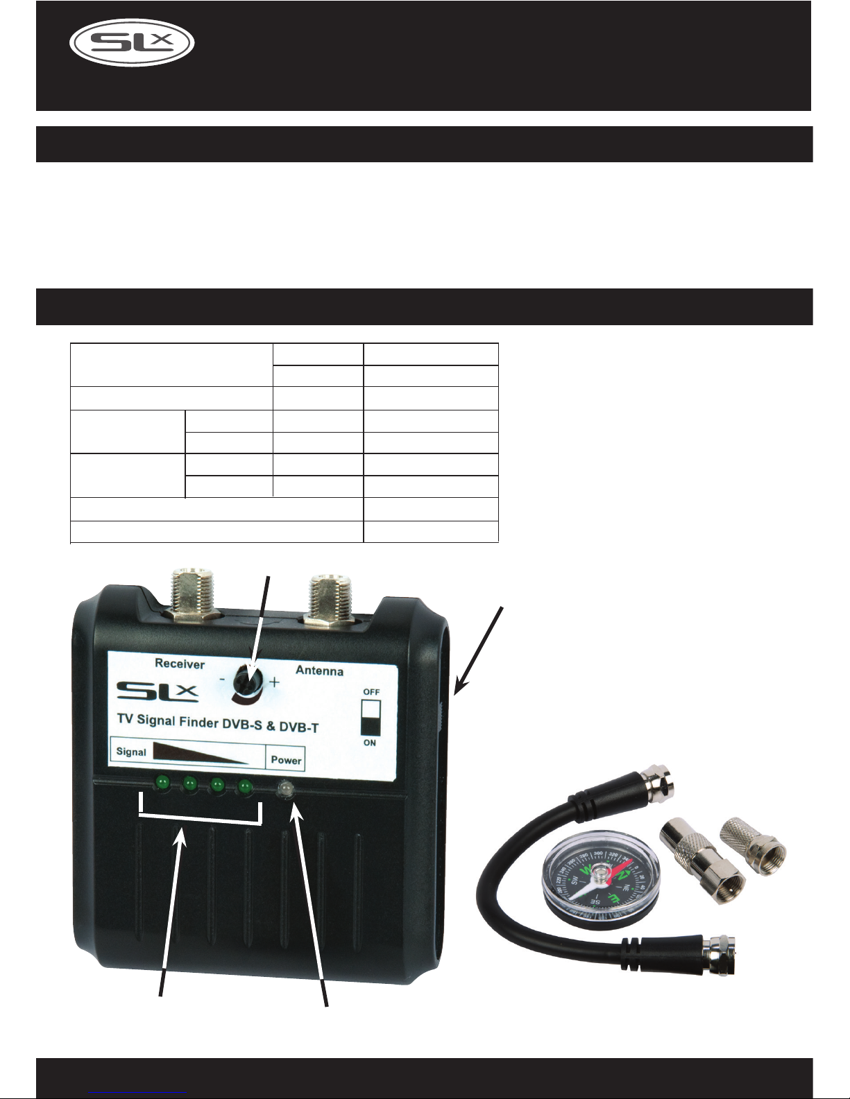
Sensitivity Control
Customer Careline: 08457 573 479 (Local rate - UK Only) Technical Support: www.philex.com/support
Dish elevation
Azimuth angle
Satellite LNB
Satellite/DVB-T
Switch
Satellite Receiver
PLEASE NOTE: No battery is required when
the nder is used to measure satellite signals.
Sucient power is provded from your
satellite receiver LNB (Dish) Input.
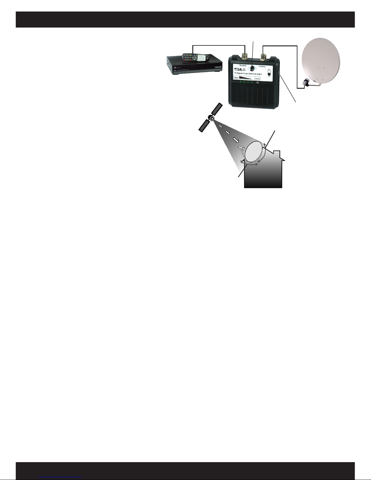
1. Slide the switch on the side of the DVB-T/
SAT Finder up into the SAT position.
2. Use a short F type cable (not supplied) to
connect the dish LNB to the F connection
marked Antenna on the DVB-T/SAT Finder.
3. Connect the LNB (Dish) Input on your satellite
receiver to the F connection marked Receiver
on the DVB-T/SAT Finder (using the satellite
downlead), switch on the satellite receiver and
the green LED indicator will light up as the
nder is powered by the satellite receiver.
4. Turn the sensitivity control fully clockwise to
maximum sensitivity. If all the LED indicators
light up at any point you can rotate the control
anti-clockwise to reduce the sensitivity.
5. Find the Azimuth and Elevation angles for the
satellite you require (for Sky and Freesat in the
UK this will be Astra 2 28.2 East) the channels
and angles can be found at:
http://www.lyngsat.com,
http://en.kingofsat.net/ or
http://www.dishpointer.com
(e.g. Brighton, England for Astra 2 (28.2 East):
Azimuth = 145.16˚, Elevation = 25.95˚)
6. Identify South (this is easiest using a compass),
and point the LNB arm south. Turn the dish
eastwards (to the left) to 5˚ less than the
Azimuth angle you have just looked up
(e.g. Brighton 145.16˚- 5˚ would be 140˚). This
is the position at which you will start your
azimuth scan. Tilt the dish so that the face is
vertical, at 90˚ to the ground (this will give you
roughly the right elevation).
7. Slowly scan (from side to side) across the sky
to the Azimuth angle plus 5˚ (e.g. Brighton
145.16 + 5˚ so nish at about 150 degrees), the
full 10˚ scan should be slow enough to take a
couple of minutes to allow your receiver to
lock onto and measure signal quality.
You are aiming to nd the position where the
most LED’s on the Finder are lit up, and
correspondingly (if you are on the correct
satellite) the signal quality and signal intensity
on the satellite receiver is highest. At this stage
the signal quality on the satellite receiver may
still be low at around 0 - 20%.
9. If no increase on the DVB-T/SAT Finder or
signal quality is noted then move the elevation
of the dish up by half a degree and repeat step
7, continue this until an increase on the Finder
and signal quality on the receiver is observed.
If there is still no increase in signal, return the
elevation to vertical and try moving the dish
elevation down by half degree increments.
10.Now focus on adjusting the Elevation (vertical
movement) without altering the Azimuth
(lateral movement). Move the Dish and LNB
assembly arm up and down slowly, until an
optimum Elevation is found.
11.The next step is to ne tune the Azimuth angle
(lateral movement). Slowly adjust the dish
angle from side to side until the most LEDs are
lit on the nder and the signal level and
quality are showing at 65% or more on the
satellite receiver. If the nder indicates a good
signal but you satellite receiver indicates no
signal strength or quality then your dish is
pointing at another satellite. Reset the dish
and continue from step 2.
12.Loosen the LNB in its holder and Rotate the
LNB to achieve maximum signal quality.
This adjusts the polarization angle and
corrects for the earth’s curvature, some LNBs
have degree markings on the top of the LNB.
If you are looking at the face of the dish with
the LNB lead hanging downwards in the 6
o’clock position, rotate the LNB clockwise to
7/8 o’clock (for As

PLEASE NOTE: To power the meter for measuring
DVB-T signals you will need to insert a 9V PP3
battery (see tting instructions below).
1. Connect a cable†from the UHF Digital
TV Aerial to the connection marked
antenna on the DVB-T/SAT Finder.
Optionally, to view and check the signal being
received, connect the DTV receiver or Digital
Freeview Box ANT. IN socket to the F connection
marked Receiver on the Finder†.
2. Slide the switch on the side of the Finder to the
TV position the green power indicator LED
should light up.
3. Turn the sensitivity control fully clockwise for
maximum sensitivity.
If at anytime all the LED indicators are lit you can
turn the sensitivity down for more accuracy.
4. As a starting position, point your aerial in the
same direction as your neighbours’ aerials or
alternatively use a compass bearing*.
Gradually rotate the aerial in a horizontal plane
to either side of your starting point until you
nd a position in which the most LED’s are lit
on the Finder.
5. If you nd more than one position giving high
signal levels select the one with widest zone
of signal strength and position the aerial in the
centre of this zone.
†To connect cables to the meter you will need to use
F connectors (not supplied).
*To nd where your nearest transmitter is and the
channels available locally visit:
http://www.digitaluk.co.uk
and ll in the coverage checker details. To nd out
your nearest transmitter’s distance and compass
tick the detailed view box.
A battery is only required when the meter is used
for detecting DVB-T signals. The nder uses a 9V
PP3 alkaline battery, to install the battery:
1. Slide the battery compartment cover open
(unclip and remove old battery, if applicable).
2. Line up the connecting studs with the correct
terminals on the battery and clip on.
3. Carefully t the battery, connecting wires and
studs into the battery compartment.
4. Slide the compartment cover back into
position making sure that connecting wires
are not trapped and that the cover is
locked securely.
Fitting the battery
Measuring DVB-T (digital Freeview™) Signals - continued
Sensitivity Control
TV Aerial
Satellite/DVB-T
Switch
Freeview™
Receiver
2 3 4
Customer Careline: 08457 573 479 (Local rate - UK Only) Technical Support: www.philex.com/support
Optional connection

•If you are in any doubt about an installation,
refer to a qualied aerial/satellite installer.
•Installations must comply with EN 50083 and
National Safety Regulations.
•When working on an installation outside,
beware of overhead power lines.
•Observe safe working practices, tread carefully
and ensure adequate lighting is available in loft
or roof space.
•Always follow manufacturer’s operating and
safety instructions before using tools and/or
equipment.
•Only carry out work outdoors at height if you
are competent in the use of ladders and related
access equipment.
•Always read and follow the manufacturer’s
instruction label axed to the ladder.
•To avoid injury always route cables or wiring
carefully. Ensure cable is correctly routed before
xing into position, taking care not to over
tighten cable clips .
General Safety Precautions
© Philex Electronic Ltd. 2016 v4.3
Waste electrical products should not be
disposed of with household waste. Please
recycle where facilities exist. Check with
your Local Authority for recycling advice.
Contents
1 x DVB-T/SAT Finder
1 x Compass
1 x F lead
1 x F plug
1 x F to coax adaptor
Customer Careline: 08457 573 479 (Local rate - UK Only) Technical Support: www.philex.com/support
For further information or any queries, please contact
Philex Customer Careline: 08457 573 479
(Local rate – UK only)
Technical Support: www.philex.com/support