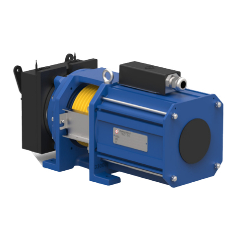
Slycma ARIANE 3.1 Quick start guide

Ref : 26702 1 07/01/15
LINEAR OPERATOR CARD
ARIANE 3.1
180W Asynchronous – Brushless Motors
COMMISSIONING MANUAL
Parc d’Activités Lyon Sud Ouest – 4 route du Dôme – F - 69630 CHAPONOST
Tel : (0033) 04 78 86 81 00 / Fax : (0033) 04 78 86 81 08

Ref : 26702 2 07/01/15
!! DISCLAIMERS !!
Your ARIANE 3.1 operator card was pre-adjusted in the factory.
After wiring according to the electrical schematic diagram attached to the
manual’s backpage, switch on the card. Then simply proceed with:
- its configuration with respect to the controller (direction of the limit
switches signals, shock, master or slave mode, car cell management by
the card, etc.),
- the learning of the travel (CMD1 mode) with an associated landing door
- the adjustment of the test door operating parameters (speeds,
slowdowns, torques, closing and opening sensitivities) with the commands
CMD3, 5 and 7,
The card has many parameters to allow it to adapt to all renovation
solutions, but it is not necessary to intervene on all these values. The
factory parameter setting allows an immediate correct operation of the
door.
A few particularities :
-Driving the Asynchronous or Brushless motor
The ARIANE 3.1 card allows driving both of these types of motors with a 230V voltage
and a 180W maximum power rating.
-Taking into account the Inspection mode
Inspection signal input to be mandatorily wired to prohibit automatic door movements
during technical services.
-Managing glazed doors (VITR and DURF parameters)
This option controls finger jammings when the door opens.
Standard EN81 – 1/2 articles 7.2.36 and 8.6.7.5
-Master 2 mode
The door opens when the cell beam is passed through and closes when the cell beam
is no longer hidden.
-Necessity of connecting the Close limit switch signal
As long as the close limit switch signal is not given, the door can re-open in case of a
skate closing problem. Therefore, the controller must wait for this signal to move the
car.
.
-Driving the auxiliary functions
Two programmable relays allow triggering a buzzer, an electro-cam, an electromagnetic
suction disc or an intermediate end stop.

Ref : 26702 3 07/01/15
ARIANE 3 OPERATING GUIDE
When the card is switched on, it executes the controller orders.
To intervene on ARIANE, you may choose from among 3 display modes, a
parameter setting mode and a manual commands mode :
Scroll the menu by successively pressing the key and make your
choice by pressing the key (If you do not validate within 3 seconds,
the default value "Fr00" is displayed).
Display modes:
- "Fr00" →display of the motor output frequency (Hz)
- "0000" →display of the position (encoder points)
- " _ _ " →display of the card Input / Output state
Parameter setting mode : - PARA →Changing the parameters
In the PARA mode, you can access all the door configuration
parameters and operating values.
Scroll the configuration parameters : successively press
Scroll the operating values : successively press
To read the value, press
To change the value, press or
To save the new value, press
To quit the mode, simultaneously press and
.
Manual commands mode : - CMD Commands CMD1 to CMD8
In the CMD mode (CMD for command), you can operate the door
independently from the controller orders
Scroll the commands mode : successively press or
To select a command, press (the display flashes)
To quit the mode, press

Ref : 26702 4 07/01/15
CONTENTS
PART 1 : Connection of the ARIANE 3.1 card
Mains power connection ........................................................... Page 5
Asynchronous motor connection ............................................... Page 5
Brushless motor connection ..................................................... Page 5
Encoder connection ................................................................. Page 6
Safety chain connection ........................................................... Page 6
Controller orders connection...................................................... Page 6
Car input cell connection .......................................................... Page 7
Controller signals connection .................................................... Page 7
Multifunction relay connection .................................................. Page 8
Wire function terminals list ...................................................... Page 8
PART 2 : Configuration according to the controller
Setting of mandatory parameters .............................................. Page 9
Details about the configuration parameters ...............................Page 10
PART 3 : Commissioning the ARIANE 3.1 card
Mechanical efficiency checking .................................................Page 13
Travel learning ......................................................................Page 13
PART 4 : Adjustment of the door operation
Operating diagrams ...............................................................Page 14
Changing a parameter ............................................................Page 14
Operating values ................................................................... Page 15
Value range table ..................................................................Page 16
PART 5 : Saving the parameters
Saving the parameters ...........................................................Page 17
Recording your own parameters ...............................................Page 18
PART 6 : Details about the command modes (CMD)
The command modes (CMD) ...................................................Page 19
Special case of a double opening travel .....................................Page 20
PART 7 : Details about the ARIANE 3.1 operations
Basic operation .................................................................... Page 21
Reset operation .....................................................................Page 22
Inspection operation ..............................................................Page 22
Parameterizable relays operation ..............................................Page 23
Fail soft operation ..................................................................Page 24
Operation with Car door locking device .....................................Page 24
Energy save operation ............................................................Page 24
PART 8 : Maintenance operations
Card Inputs/Outputs display ....................................................Page 25
Operating faults display ..........................................................Page 26
Details about operating faults ..................................................Page 27
Encoder position display .........................................................Page 28
Numbers of cycles display .......................................................Page 28

Ref : 26702 5 07/01/15
Part 1 : The Ariane 3 card connections
The card efficiency is first subjected to a mechanical
setting in conformity with the door.
Necessary connectors are supplied in a bag.
MAINS POWER CONNECTION – 3x7.62 – 230V 50Hz – 2A connector
The 230 V power supply must not come
from the primary of a 110/230/400V
transformer because a damaging
overvoltage can occur if the transformer
is not loaded.
The connector must not be handled with power switched on
If the voltage between neutral and ground is very different from 0 volts,
power the card via an insulating transformer (example : case of connection
in TI state).
ASYNCHRONOUS MOTOR CONNECTION : 4x minifit (made in
factory)
Make sure that the motor cable shielding
is properly connected to the Ariane card
package.
Make sure that the motor’s ground is
connected to the connector (EMC
requirement).
BRUSHLESS MOTOR CONNECTION : 4x motor minifit and 6x hall
effect sensors microfit (made in factory)
Make sure that the motor cable shielding is
properly connected to the package and that
the 3 phase wires are properly installed on
the minifit connector.
Make sure that the 6x hall effect sensors microfit
connector of the Brushless motor is properly
connected to the right side of the ARIANE body.

Ref : 26702 6 07/01/15
ENCODER CONNECTION – 4x microfit connector (made in factory)
For an Asynchronous motor
Connection of the counting cells.
Make sure that the encoder’s 6 wires are
properly connected, that the crimpings are in
good condition, and that the wire is
immobilized
For a Brushless motor
Connection of the encoder integrated with the
motor
Make sure that the 4 wires are crimped
correctly and that the cable is immobilized
SAFETY CHAIN CONNECTION – 2 x 5.08 connector
Connect the safety chain to the 2 x 5.08 connector. Check
the factory wiring of the door contacts on the 4 x 5.08
connector is conformity with the electrical drawing regarding
there is one or two contacts. (One in lateral opening, 2 in
central opening)
There is no interaction between the card’s operation and the
safety contacts.
CONTROLLER COMMANDS CONNECTION – 6 x 5.08 connector
All the orders must come from dry contacts which switch
the 0V common supplied by the card.
It is not necessary to apply voltages to these inputs.
Warning : When an operator driven by contactors is
replaced, do not use the old contactors flakes as
command contacts, but use relays which switch low
currents (20 mA at 12 VDC).

Ref : 26702 7 07/01/15
The required standards are the open order, the close order and the inspection
information signal.
If only the close order is available, the open order must
be bypassed. The close and nudging orders have priority
over the open order.
The inspection connection is mandatory
to inhibit any untimely door movement
during a technical service. (Standard
EN81 – 1/2 article 14.2.1.3 a)
CAR CELL CONNECTION – 3 x 5.08 connector
If the car cell is controlled by the card, a NC (normally closed) dry
contact must be connected between the card’s OV common and
the Cell information signal input.
This input may also be used for a ’ReOpening pushbutton in the
carequipped with a NC contact. It may be connected in series
with the cabin cell’s NC signal input.
If necessary for the cell, a +12V power supply is provided.
The use of this input is conditioned by the CELLand MODE
parameters.
CONTROLLER SIGNALS CONNECTION – 6 x 5.08 connector
Connect the Limit switch and Shock signal returns to
the controller.
These signals are dry contact relay outputs which
require minimum switching currents of 10mA.
The direction of the NO (normally open) or NC
(normally closed) limit switches is selected with the
FDC(Limit switch) parameter.
The shock signal also restores the car cell signal if
the car cell is connected to the card.
The direction of the NO or NC Shock signal is
selected by the CHOC(SHOCK) parameter.
Warning : the closing limit switch connection is mandatory so that
the car starts moving only when the close cycle is totally complete
(skate closed, for example) and not as soon as the door contact
closes.

Ref : 26702 8 07/01/15
MULTIFUNCTION RELAY CONNECTION – 4 x 5.08 connector
Two programmable commands may be
connected to the RMF1 and RMF2 outputs, which
are two dry contact relays.
The driven device type is selected with the
RMF1and RMF2parameters, namely :
- A buzzer, which will be activated during the
learning, reset, nudging and fail soft operation.
- An electromagnetic suction disc, which will keep
the door panels closed
- An electro-cam, which will unlock swinging
doors or articulated sliding doors
- An electromagnetic intermediate open end stop
External power supplies must be provided for the
devices
The maximum interrupting capacity of the relays is
6A for 250 VDC and 15A for 400 VAC
WIRE FUNCTION ASSIGNMENTS LIST

Ref : 26702 9 07/01/15
Terminal n° Assignment
Ph, N, T Mains power supply
L1, L2, L3, T Motor connection
5, 6 Safety chain connection
7, 8, 9, 10 Door contacts connection
14, 15 Shock signal
16, 17 Closing limit switch stop signal
18, 19 Opening limit switch stop signal
25 + 12 VDC
26, 27 NC (normally closed) Cell input
28 Inspection NO (normally opened) command input
29 Nudging NO Command input (forced closing)
30 Closing NO command input
31 Intermediate Opening NO command input
32 Complete opening NO command input
33 Common 0V of the commands
PART 2 : Configuration according to the controller
Scroll the menus by successively pressing ,
and select PARAby pressing .
Scroll the parameters with
To read the value, press
To change the value, press
To save the new value, press
SETTING OF THE MANDATORY PARAMETERS
Display order of the parameters :
→MSTF Hold under voltage closing OUI(YES) /NON(NO)/DEPL Set in Factory
→MSTO Hold under voltage opening OUI (YES)/NON(NO) Set in Factory
→MODE Operating mode : ESCL/MAI1/MAI2
→CHOC Shock contact direction / Controller : NO or NF
→FdC Limit switch contact direction / Controller : NO or NF
→SMOT Motor rotating direction DIR/INV Set in Factory

Ref : 26702 10 07/01/15
→VITR Glazing option OUI/NON Set in Factory
→CELL Cell management : NON/OUI/LIMI
→TYPE Door type: Mobile (MOBI), Swinging (BATT), Fixed (FI) Set in Factory
MOBI or FI are the type of skate on automatic doors
→rMF2 MULTIFUNCTION RELAY 2 : buZZ/butE/Vent/CAME
→rMF1 MULTIFUNCTION RELAY 1 : buZZ/butE/Vent/CAME
→PINI Factory parameters INI, SAVE, IN01, ..., IN30 Set in Factory
→CYCL No. of cycles performed x 1000 Information
→ERR Last 10 recorded errors, Errx/EFFA Information
→MOTR ASYN/BRUS motor type selection Set in Factory
→BAUD CAN parameter Not used
→PRTE CAN parameter Not used
END of CONFIGURATION
To exit the parametersmenu, simultaneously press and .
If the card has never been started, it displays APPr

Ref : 26702 11 07/01/15
CONFIGURATION PARAMETERS DETAILS
MSTF Hold closed under voltage OUI, NON or DEPL (YES,
NO, or DISPL)
DEPL = Moving : The motor is held under voltage if the
closing input is activated. Generally, non(no) for
automatic doors and oui(yes) for swinging doors.
If there is a mechanical holding hook to keep the
door in closed position, select NON (NO).
MSTO Hold opened under voltage OUI, NON (YES, NO).
Generally, oui(yes) for automatic doors and non
(no) for swinging doors.
In case a mechanical retaining hook is present to
keep the door in the open position, select NON (NO).
MODE Behaviour choice in case door blocking in closing
ESCL : Slave mode. Door not opened, but the Obstacle
relay activated. The controller time out reversalmust
be set to 0.
MA-1: Master mode 1. Door completely opened with
time out in case blocking
or cell detection with the Obstacle relay activated.
MA-2: Master mode 2. Door opens as long as the cell
signal lasts in case of cell detection. Otherwise, door
immediately closed.
The Obstacle relay is activated in case of a shock, or in
case of complete reopening driven by the cell.
CHOC The OBSTACLE relay operating direction : NO, NF
(Normally Open, Normally Closed)
FDC Operating direction of the relays FdC-O (OLS)/FdC-F
(CLS):
NO, NF (Normally Open, Normally Closed)
SMOT Motor direction software reversal : DIR or INV
VITR Glazed door option : OUI, NON (YES, NO) allows
preventing finger jamming as door opens.

Ref : 26702 12 07/01/15
CELL Cell input management option : OUI, NON, LIMI
(YES, NO, LIMI)
The cell must be a normally closed (NF) and must
be connected to ARIANE
The cell is automatically viewed during learning and filled
in. The CELL parameter allows eliminating it, if
necessary.
With the LIMI option : The cell is inhibited as the door is
reset after a mains power failure (230 VAC).
TYPE Door type selection :
BATT : Operator installed in front of a swinging door
FI : Operator with fixed blade
MOBI : Operator with mobile skate
Warning ! In case of a door type change, a new
learning procedure must be performed (CMD1).
RMF2 Choice of multifunction output relays use
BUZZ : a buzzer sounds when the door moves
RMF1 Learning, reset, nudging movements or fail stop.
BUTE : intermediate end stop control when two open
travel ranges are to be used.
CAME : driving of an electro-cam for swinging door type
BATTor MOBI, or for shutter door type FI.
VENT : an electromagnetic suction disc is driven to
keep the door locked if the close order is maintained.
Pini Allows loading the pre-programmed or saved adjustment
values after the Asynchronous or Brushless motor
type (MOTR) is selected.
INIT allows restoring the last saved parameter setting.
SAVE allows saving the current adjustment.
In01, In02, In03 etc. … allows loading the factory
parameter range tables corresponding to the various
door types.

Ref : 26702 13 07/01/15
List of the PINI value tables :
IN 01 IN 02 IN 03 IN 04 IN 05 IN 06
IN 07 IN 08 IN 09 IN 10 IN 11 IN 12
IN 13 IN 14 IN 15 IN 16 IN 17 IN 18
SHEET METAL GLAZED SHEET METAL
2VOT / 3VOT
CO … 850 CO 900 … 1200 Co and CH very large
SHEET METAL GLAZED SHEET METAL GLAZED SHEET METAL GLAZED
2VOC
CO … 850 CO 900 … 1200 Co and CH very large
GLAZED
4VOC - 6VOC
CO … 850 CO 900 … 1200 Co and CH very large
SHEET METAL GLAZED SHEET METAL GLAZED SHEET METAL
SHEET METAL GLAZED
GLAZED
To confirm the selected parameters, quit parameter
setting by simultaneously pressing and when all
the parameter settings are made.
CYCL Informative display : Indicates the number of cycles
in thousands performed by the card since its
commissioning.
This number cannot be reset to 0.
Err Informative display : Indicates the last 10 errors
detected by the card.
Motr Choice of the type of motor to be driven :
asynchronous ASYnor brushless bruS
bAud PrtE CAN parameters not used currently

Ref : 26702 14 07/01/15
PART 3 : Starting the ARIANE 3 card
When the parameter setting of the door configuration with respect to
the controller is confirmed, the ARIANE 3 card can enter in operation.
Move the car to a floor in order to have a landing door
associated with the car door.
MECHANICAL EFFICIENCY CHECK
Use the CMD3 function to run the motor at a slow opening and
closing speed by proceeding as follows :
Scroll the menus by successively pressing and select
CMD
by
pressing .
Scroll the CMD functions with up to CMD3
To start the CMD3 function, press
To operate the motor in opening, press
To operate the motor in closing, press
To exit from the CMD3 command, press
Make sure that the motor rotates in the right direction. If not, return
to the parameters and change the SMotparameter.
Make sure that the door operates correctly mechanically from end
stop to end stop and that the skate correctly unlocks the landing door.
OPERATOR TRAVEL LEARNING
Start the travel learning with the CMD1 command.
Scroll the menus by successively pressing and select
CMD
by
pressing .
Scroll the CMD functions with up to CMD1
To start the CMD1 function, press
The door opens up to the end stop, waits a few seconds to confirm its
0 position, and then closes until the skate is completely closed and
waits a few seconds to confirm the travel value.
When the learning is finished, the card automatically exits from the
CMD1 command and waits for controller orders.
THE DOOR IS READY TO OPERATE

Ref : 26702 15 07/01/15
PART 4 : Adjustment of the door operation
To make the door’s operation even more accurate, you can also
trigger on speeds (F), acceleration and deceleration ramps (R),
torques (U) and the travels (C).
OPERATING DIAGRAMS
OPERATING PARAMETERS WITH MOBILE SKATE (TYPE = MOB1)
RA-O
RD-O RD-F
RA-O RD-F
DURO DURF
OPERATING PARAMETERS WITH FIXED SKATE (TYPE = FI)
RA-O
RD-O RD-F
RA-O
DURO DURF
OPERATING PARAMETERS IN FRONT OF SWINGING DOOR (TYPE = BATT)
RD-O RD-F
DURO DURF
U2-O U2-F
FP-O FP-F
<------- CS-F ------->
FS-O RA-F FS-F
U1-S U-FR FF-O U-FR FF-F U1-S
U1-O U1-F
<----- CS-O -----> <-- CL-O --> < CL-F
>
Skate travel Panels travel (Clea opening) Panels travel (Clea opening) Skate travel
FP-O FP-F
U2-O U2-F
FS-O RA-F
U-FR FF-F
U1-O U1-F
<----- CS-O------
>
<-- CL-O -->
<
--- CL-F ---
>
U1-S U-FR FF-O
FF-F
Panels travel (Clea opening) Panels travel (Clea opening)
FP-O FP-F
U2-O U2-F
RA-O RA-F
U-FR FF-O U-FR
U1-O U1-F
<-- CL-O -->
<
--- CL-F ---
>
Panels travel (Clea opening) Panels travel (Clea opening)
CHANGING A PARAMETER
Scroll the menus by successively pressing ,
and select PARAby pressing .
Scroll the parameters with
To read the value, press
To change value, press
To save the new value, press
To exit parameter setting, simultaneously press and

Ref : 26702 16 07/01/15
OPERATING VALUES
The speeds correspond to the frequency sent to the motor and
therefore are expressed in Hz.
They correspond to the various door opening and closing phases. They are called
by their abbreviation : FP-O = Opening Cruise Frequency, or FP-F = Closing
Cruise Frequency
The acceleration or deceleration ramps correspond to the time it
takes to go from 0 to 50 Hz, or from 50 to 0 Hz. They are expressed
in seconds.
By reducing the ramp value, the speed is more abruptly changed, and conversely.
They are called by their abbreviation : RD-O = Opening Deceleration Ramp and
RD-F = Closing Deceleration Ramp.
The travels are expressed in encoder point, which corresponds
roughly to millimetres.
The skate travels allow locking or unlocking the locks in slow speed in order to
minimise the noise.
The slow travels allow adjusting the door dockings according to their speed or
their inertia.
The hardnesses are expressed in % of speed drop.
The card records the real cruise speed each time the door is opened or closed and
analyses abnormal deviations. An exceeding of the adjusted percentage in DURF
during closing triggers a re-opening, and in DURO for opening triggers a finger
unjamming movement for glazed doors.
The torques are directly dependent on the voltage sent to the
motor and therefore are expressed in Volts.
A minimum voltage value is defined for a frequency of 2 Hz (U1-..) and a
maximum voltage value for a frequency of 50 Hz (U2-..).
The voltage sent to the motor for the operation is calculated between these two
extreme values according to the frequency.
There are two separate parameter settings :
Moving torques
Opening (U1-O, U2-O), closing (U1-F, U2-F) and skate (U1-S, U2-S).
Braking torque : U-FR
It allows holding heavy doors better when operation at high speeds is
desired.

Ref : 26702 17 07/01/15
VALUE RANGE TABLE
CAN Car door number PrtE 1, 2 ou 3
CAN Communication speed bAud bauds
Motor type Motr ASYn, bruS
Fault stack Err 0 à 10
Number of cycles in thousands CyCL x 1000
Pre-set table choice Pini 01 à 99
Multifunction relay no. 1 rMF1 buZZ, butE, CAME, Vent
Multifunction relay no. 2 rMF2 butE, CAME, Vent, buZZ
Operator type tyPE Mobi, Fi, bAt
Car Cell connected CELL non, oui
Glazed door Vitr non, oui
Motor direction Smot dir, inv
Travel end stop direction FdC nF, nO
Shock signal direction CHoC nO, nF
Shock management mode ModE MAi1, MAi2, Escl
Hold under voltage during opening Msto yes, no
Hold under voltage during closing MstF yes, no
Opening Cruise Frequency FP-O 2 to 50 Hz
End of Opening Frequency FF-O 2 to 5 Hz
Opening Skate Frequency FS-O 3 to 7 Hz
Opening Handling Frequency FM-O 5 to 10 Hz
Closing Cruise Frequency FP-F 2 to 50 Hz
End of Closing Frequency FF-F 2 to 5 Hz
Closing Skate Frequency FS-F 3 to 7 Hz
Closing controller Frequency FM-F 5 to 10 Hz
Opening Acceleration Ramp RA-O 1 to 3 s
Opening Deceleration Ramp RD-O 1 to 3 s
Opening Acceleration Ramp RA-F 1 to 3 s
Opening Deceleration Ramp RD-F 1 to 3 s
Slow Closing Travel CL-F 1 to 150 Pts
Slow Opening Travel CL-O 1 to 200 Pts
Braking Torque u-Fr 40 to 100 Volts
Opening Hardness durO 0 to 100 %
Closing Hardness durF 0 to 100 %
Min Opening Voltage U1-O 20 to 70 Volts
Max Opening Voltage U2-O 70 to 180 Volts
Min Closing Voltage U1-F 20 to 50 Volts
Max Closing Voltage U2-F 50 to 140 Volts
Min Skate Voltage U1-S 20 to 50 Volts
Max Skate Voltage U2-S 50 to 180 Volts
Opening Skate Travel CS-O 10 to 70 Pts
Closing Skate Travel CS-F 10 to 50 Pts
Open Order Wait Time tA-O 15 to 90 min
Cruise Frequency Reduction R-FP 0 to 50 %
CONFIGURATION
ENTRY POINT IN THE TABLE : "-" = ↗, "+" =↘
O P E R A T I O N
END OF USER AREA

Ref : 26702 18 07/01/15
PART 5 : Saving the parameters
The ARIANE card uses a list of so-called workparameters to operate;
these parameters correspond to those which can be read and changed.
The configuration parameters: MSTO, MSTF, etc.
The operating values: FP-O, FF-O, etc.
The manufacturer parameters: Hidden in use
After the door’s operation has been adjusted, all these values may be
saved to a "save" list by the "SAVE" function so that this adjustment may
be restored at any time with the INITfunction.
,,,
Multifunction relay no. 2 rMF2
Operator type tyPE
Cabin cell connected CELL
Glazed door Vitr
Motor direction Smot
Limit switches stops directio
n
FdC
Shock signal directi on CHoC
Shock management mode ModE
Hold under open voltage Msto
Hold under close voltage MstF
Opening Cruise frequency FP-O
End Of Opening frequency FF-O
Opening Sabre frequency FS-O
,,,
IN xx
INIT
List N°1
List N°2
Work parameters Saved adjusted list
List N°3
List N°…
SAVE
TABLES OF STORED FACTORY VALUES USED VALUE TABLE SAVED SITE
CLASSIFIED BY DOOR TYPE CAN BE READ AND CHANGED PARAMETERS TABLE
To avoid an accidental backup, the "SAVE" instruction is only
accessible in manufacturer mode in the PINIconfiguration
parameter.
To go into manufacturer mode and make a save :
1. Switch off the card power and wait for the relays to break
2. Press and hold the and " keys
3. Still holding the keys, switch power on again
4. When "FP-O" is displayed, release the keys. You are in manufacturer
mode
5. Scroll the parameters with up to PINI
6. Press to validate the choice
7. To reach the SAVEfunction, press
8. To make a save, press
9. Simultaneously press and to confirm the save

Ref : 26702 19 07/01/15
RECORDING YOUR ADJUSTED PARAMETERS
Don’t forget to write down the parameters at the end of commissioning for
maintenance.
Type Description Name Range Value
CAN Car door number PrtE 1, 2 ou 3
CAN Communication speed bAud bauds
Motor type Motr ASYn, bruS
Fault stack Err 0 à 10
Number of cycles in thousands CyCL x 1000
Pre-set table choice Pini 01 à 99
Multifunction relay no. 1 rMF1 buZZ, butE, CAME, Vent
Multifunction relay no. 2 rMF2 butE, CAME, Vent, buZZ
Operator type tyPE Mobi, Fi, bAt
Car Cell connected CELL non, oui
Glazed door Vitr non, oui
Motor direction Smot dir, inv
Travel end stop direction FdC nF, nO
Shock signal direction CHoC nO, nF
Shock management mode ModE MAi1, MAi2, Escl
Hold under voltage during opening Msto yes, no
Hold under voltage during closing MstF yes, no
Opening Cruise Frequency FP-O 2 to 50 Hz
End of Opening Frequency FF-O 2 to 5 Hz
Opening Skate Frequency FS-O 3 to 7 Hz
Opening Handling Frequency FM-O 5 to 10 Hz
Closing Cruise Frequency FP-F 2 to 50 Hz
End of Closing Frequency FF-F 2 to 5 Hz
Closing Skate Frequency FS-F 3 to 7 Hz
Closing controller Frequency FM-F 5 to 10 Hz
Opening Acceleration Ramp RA-O 1 to 3 s
Opening Deceleration Ramp RD-O 1 to 3 s
Opening Acceleration Ramp RA-F 1 to 3 s
Opening Deceleration Ramp RD-F 1 to 3 s
Slow Closing Travel CL-F 1 to 150 Pts
Slow Opening Travel CL-O 1 to 200 Pts
Braking Torque u-Fr 40 to 100 Volts
Opening Hardness durO 0 to 100 %
Closing Hardness durF 0 to 100 %
Min Opening Voltage U1-O 20 to 70 Volts
Max Opening Voltage U2-O 70 to 180 Volts
Min Closing Voltage U1-F 20 to 50 Volts
Max Closing Voltage U2-F 50 to 140 Volts
Min Skate Voltage U1-S 20 to 50 Volts
Max Skate Voltage U2-S 50 to 180 Volts
Opening Skate Travel CS-O 10 to 70 Pts
Closing Skate Travel CS-F 10 to 50 Pts
Open Order Wait Time tA-O 15 to 90 min
Cruise Frequency Reduction R-FP 0 to 50 %
CONFIGURATION
ENTRY POINT IN THE TABLE : "-" = ↗, "+" =↘
O P E R A T I O N
END OF USER AREA

Ref : 26702 20 07/01/15
PART 6 : Details about the command modes (CMD)
With the various command modes (CMD), you can test the door’s
operation according to the adjustments made.
CMD0 : Normal operation :
The card simply executes the controller orders and communicates the
shock and travel end stop signals.
CMD1 : Learning the total travel
When this command is started, the display indicates APPR. The card
triggers an open cycle and then a close cycle at the end of which the
encoder’s absolute value is saved as the reference travel.
If a learning ends not correctly, the
APPR
or
Err6
message (cf.
page 23) will remain displayed at the end of the learning. The
learning should be redone after the fault is eliminated.
CMD3 : Direct motor command
In this mode, the motor is activated in the open direction and in the
close direction .
The motor is stopped when the button is released. This command is,
among others, intended to check the motor’s rotating direction or the
door’s operation.
To quit this mode, press .
This mode activates only the motor and not the card outputs.
CMD5 : Openings and closings by
O
and
F
(Close)
Accessible only if the learning (CMD1) has been done. Pressing
interrupts a close cycle and starts an open cycle. Pressing interrupts
an open cycle and starts a close cycle.
To quit the command mode, press .
This mode does not activate the shock and limit switch stop
signals
CMD7 : Open / close cycles
Accessible only if the learning (CMD1) has been done. In this mode, the
door continuously carries out open/close cycles. Whenever or is
pressed, the door’s opening direction is reversed.
To quit this mode, press .
This mode does not activate the shock and limit switch stop
signals.
Table of contents
Popular Engine manuals by other brands
DANA
DANA 4450-1 parts list

HEIDENHAIN
HEIDENHAIN QAN 260L Replacing Instructions
MerCruiser
MerCruiser Scorpion 350 user manual
Briggs & Stratton
Briggs & Stratton 9B900 Operating & maintenance instructions
Stober
Stober PE22 operating manual
Ingersoll-Rand
Ingersoll-Rand MULTI-VANE 3800 Series Operation and Maintenance Information

