SMA Regelsysteme GmbH Sunny Boy 2800i User manual
SB2800i-11:SE0504
Sunny Boy 2800i
String Inverter Sunny Boy 2800i
The New Generation of PV System Technology
Installation Guide


Table of Contents
1 Introduction . . . . . . . . . . . . . . . . . . . 3
2 Safety Instructions. . . . . . . . . . . . . . . 5
3 Overview. . . . . . . . . . . . . . . . . . . . . 7
3.1 Device Description. . . . . . . . . . . . . . . . . . 7
3.2 External Dimensions. . . . . . . . . . . . . . . . . 8
4 Requirements for the Installation . . . . 9
4.1 Requirements: Mounting Place . . . . . . . . . 9
4.2 Requirements: PV-Modules . . . . . . . . . . . 11
4.3 Requirements: Grid 230 V~ (AC) . . . . . . 12
5 Installation . . . . . . . . . . . . . . . . . . . 15
5.1 Mounting . . . . . . . . . . . . . . . . . . . . . . . 15
5.2 Electrical Installation . . . . . . . . . . . . . . . 16
5.3 Activation . . . . . . . . . . . . . . . . . . . . . . . 21
6 Opening and closing the Sunny Boy. 23
6.1 Opening the Sunny Boy . . . . . . . . . . . . . 23
6.2 Closing the Sunny Boy . . . . . . . . . . . . . . 23
7 Communication. . . . . . . . . . . . . . . . 25
7.1 Powerline Communication . . . . . . . . . . . 25
7.2 RS232 Communication . . . . . . . . . . . . . 26
7.3 RS485 Communication . . . . . . . . . . . . . 28
8 Exchanging varistors. . . . . . . . . . . . 31
9 Contact . . . . . . . . . . . . . . . . . . . . . 35

Revision History
Document number Changes Author
SB2800i-11:SE0504 First Issue Siebert

Installation Guide Introduction
SB2800i-11:SE0504 SMA Regelsysteme GmbH 3
1Introduction
This document gives short installation instructions for
electricians only. It helps to swiftly and correctly install and
commission an SMA inverter type „SB 2800i“.
For detailed technical data and operating instructions please
see the Operating Instructions.
The „GenAu“ tool will help to dimension and check the size of
your strings with respect to the Sunny Boy you intend to use. The
„GenAu“ tool is available for download at www.SMA.de.
If you have any further questions please do not hesitate to call
the Sunny Boy hotline on the following number:
+49 561 9522-499
All trademarks mentioned in this Installation Guide are
accepted.

Introduction Installation Guide
4 SMA Regelsysteme GmbH SB2800i-11:SE0504
Installation Guide Safety Instructions
SB2800i-11:SE0504 SMA Regelsysteme GmbH 5
2SafetyInstructions
Only a qualified electrician may work on the
open Sunny Boy! This work is only permissible
if the AC and DC power supply are safely
disconnected from the Sunny Boy.
The Sunny Boy must be disconnected from the grid and secured
against accidental reconnection. Connections to the PV
generator must be disconnected as well.
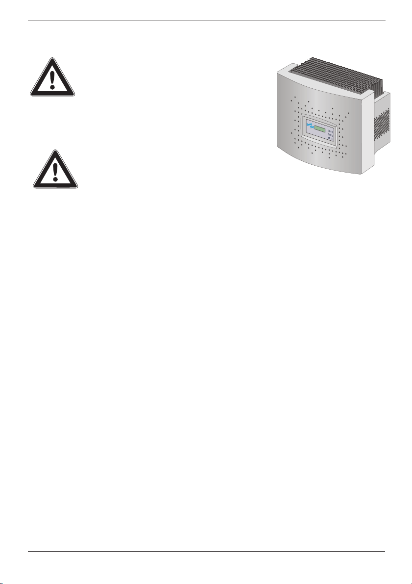
When this has been done, always wait for
approx. 5 minutes so that the capacitors in the
Sunny Boy can be discharged. Only then may
the lid be opened and the safe isolation from
power supply be checked.
The Sunny Boy 2800i is equipped with the anti-islanding unit
„SMA grid guard“. The Sunny Boy 2800i therefore complies
with the VDEW guidelines for grid interactive inverters and the
DIN VDE 0126 (4.99) specified in this regulation.
The Sunny Boy is equipped with high
voltage capacitors that can contain lethal
voltages even when disconnected from
supply power for some time.

Safety Instructions Installation Guide
6 SMA Regelsysteme GmbH SB2800i-11:SE0504

Installation Guide Overview
SB2800i-11:SE0504 SMA Regelsysteme GmbH 7
3 Overview
3.1 Device Description
The following figure shows the different components and
connection areas of an open Sunny Boy 2800i inverter.
Fig. 3.1: Inside view of the Sunny Boy 2800i
Varistors,
page 31
Terminals (AC)
page 17
PV input plugs (DC),
page 19
Communication socket
(RS232, RS485, PLC),
page 25
Terminal for PE
LEDs indicating
operating state
Socket for
display unit
(Sunny Display)
Communication
terminal
Overview Installation Guide
8 SMA Regelsysteme GmbH SB2800i-11:SE0504
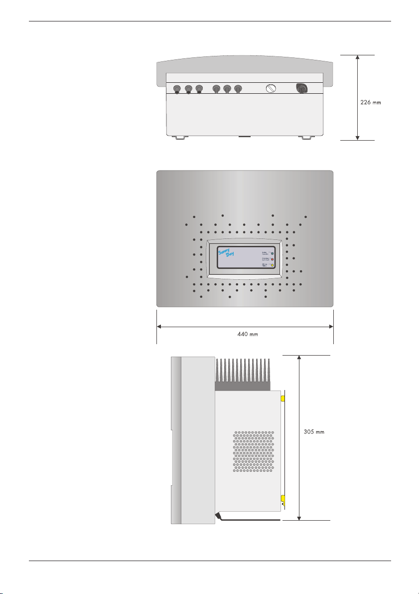
3.2 External Dimensions
Abb. 3.2: Size of the Sunny Boy 2800i

Installation Guide Requirements for the Installation
SB2800i-11:SE0504 SMA Regelsysteme GmbH 9
4 Requirements for the Installation
Please make sure to fulfill all conditions below before installing
and commissioning the Sunny Boy.
4.1 Requirements: Mounting Place
The Sunny Boy 2800i has a relatively high weight of 31 kg.
Please keep this in mind when selecting the place where and how
to mount the Sunny Boy.
The ambient temperature should be within -25 °C
and + 60 °C.
The Sunny Boy 2800i is only for inside installation. It should be
mounted in a place whithout high temperatures - otherwise this
may reduce the yield of the PV plant.
It can be mounted straight or to the back. To ensure optimum
energy yield and easy operation it should be mounted straight
and on eye level.
Important for the selection of the location:
Unintended removal of the Multi-Contact®
snap-cable connectors can damage the
connectors and even result in serious injuries.
Install the Sunny Boy in a place where an
unintended removal of the Multi-Contact®
connectors (e. g. by children) is not possible.
Some parts of the Sunny Boy can reach
temperatures over 80 °C. Keep a suitable
distance to flammable materials!
Never install the Sunny Boy in areas that likely
contain explosive athmospheres (battery
rooms, fuel storage rooms etc.)!
Install the Sunny Boy 2800i in a fairly dust free
environment.
31 kg
Requirements for the Installation Installation Guide
10 SMA Regelsysteme GmbH SB2800i-11:SE0504
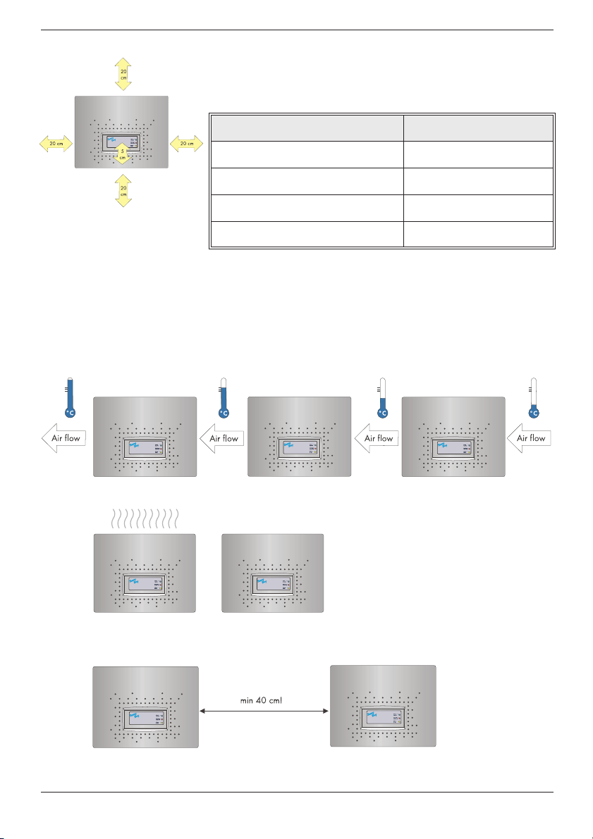
Please make sure there is a sufficient space for heat dissipation!
In a normal environment the following clearance should be
provided for a single Sunny Boy 2800i
Table 4.1: Minimum clearance
If you want to install several Sunny Boy 2800i side by side on the
same level, pay attention to the minimum distance between them.
If there is not enough space between the devices, the left Sunny
Boy will reduce the yield of the PV plant because of the
incomming air temperature.
The minimum space between two Sunny Boy 2800i has to be
40 cm.
Minimum clearance
Lateral 20 cm
Top 20 cm
Bottom 20 cm
Front 5 cm
Pay attention to the required minimum
clearance for the Sunny Boy 2800i
Two or more Sunny Boy 2800i
may not be mounted directly to
each other.

Installation Guide Requirements for the Installation
SB2800i-11:SE0504 SMA Regelsysteme GmbH 11
In a living area the Sunny Boy should not be mounted on plaster
panels, thin wooden panels etc. in order to avoid noises.
We recommend to install the inverter on a firm and sturdy
surface.
Mounting the Sunny Boy on a thin sur-
face may emit a slight noise!
Requirements for the Installation Installation Guide
12 SMA Regelsysteme GmbH SB2800i-11:SE0504
4.2 Requirements: PV-Modules
The Sunny Boy 2800i is designed for the connection of up to three
strings (PV modules connected in series).
The „ GenAu“ tool will help to dimension and check the size of
your strings with respect to the Sunny Boy you intend to use. The
„GenAu“ tool is available for download at www.SMA.de.
The device has six Multi-Contact plug connectors (two for each
string). The connecting cables of the PV panel therefore have to
be equipped with such plug connectors as well.
A connection kit for connection of loose cable ends in a string can
be purchased as an accessory (SMA order name: „SWR-MC“).)
Limits for DC input
Max. voltage 600 V (DC)
Installation Guide Requirements for the Installation
SB2800i-11:SE0504 SMA Regelsysteme GmbH 13
4.3 Requirements: Grid 230 V~ (AC)
The relevant technical regulations as well as specific requirements
defined by the local public utility have to be complied with.
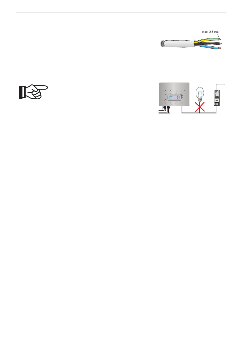
The terminals of the Sunny Boy 2800i are suitable for cables with
a cross-section of up to 2.5 mm². The Sunny Boy is connected with
three wires (L, N, PE).
Each connection to a Sunny Boy 2800i must be
equipped with a separate circuit breaker 16 A.
No other consumers may be connected to the
cable.
The Sunny Boy has to be connected
to grid with three wires!
No additional consumers may be
connected between the Sunny Boy
and the fuse!

Requirements for the Installation Installation Guide
14 SMA Regelsysteme GmbH SB2800i-11:SE0504
The impedance at the AC connection point of the Sunny Boy
3000 must be below 2 Ohm in order to ensure a reliable function
of the anti-islanding unit. You should furthermore have a suitable
cable cross-section in order to keep the losses below 1 % at
nominal power. The according losses with respect to cable length
and cross-section are illustrated below:
Fig. 4.1: Losses in AC cable
The Sunny Boy 2800i is designed for 230 V grids. The voltage
should be within 198 V and 260 V and the frequency should be
within 49.8 Hz and 50.2 Hz.
Table 4.2: Limits for AC output of the Sunny Boy 2800i
Limits for AC Output
Voltage range 198 V ... 260 V
Frequency range 49.8 Hz ... 50.2 Hz
Voltage range
(without ENS) 180 V ... 260 V
Frequency range
(without ENS) 45.5 Hz ... 54.5 Hz
Limits for AC output
198 V ... 260 V
49.8 Hz ... 50.2 Hz
SB2800i-11-SE0504-TEXT.fm Seite 14 Freitag, 20. Februar 2004 9:19 09
Installation Guide Installation
SB2800i-11:SE0504 SMA Regelsysteme GmbH 15
5 Installation
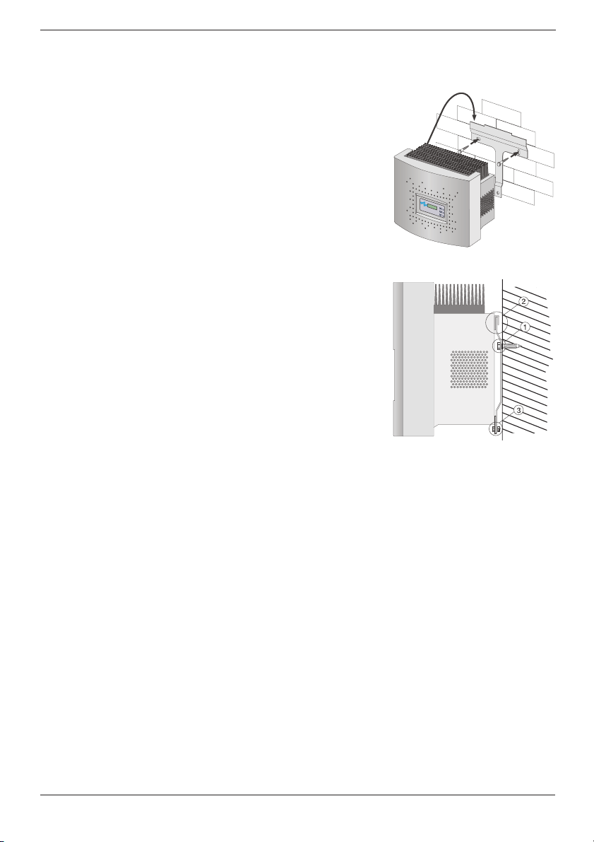
5.1 Mounting
For trouble-free mounting of the Sunny Boy 2800i we recommend
to use the bracket for wall installation included in delivery. You
can mount it vertically in firm concrete or stone walls with e. g.
stainless steel 8 mm x 50 mm hexagon screws according to DIN
571 and with dowels type SX8.
Keep the weight of the Sunny Boy 2800i (31 kg) in mind.
1. Mount the bracket. To mark the positions for drill holes you
can also use the bracket as a drilling template.
2. Hang the upper fixing straps on the Sunny Boy 2800i into
the bracket (2) so that it cannot be shifted sideways any
more.
3. Secure the Sunny Boy 2800i against lifting off by screwing
the M6x10 screw (included in delivery) into the lower middle
fixing strap (3).
4. Ensure that the Sunny Boy 2800i has been tightly fastened.
Installation Installation Guide
16 SMA Regelsysteme GmbH SB2800i-11:SE0504
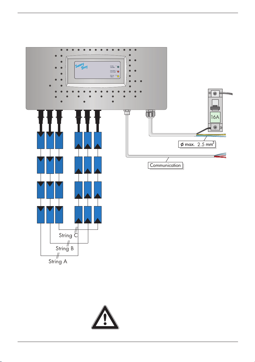
5.2 Electrical Installation
The following figure shows the complete cabling of a Sunny Boy
2800i:
Depending on the type of PV module used, it is reasonable to
connect only one String or to use two or three parallel Strings.
Thus, the module has three plus poles and three minus poles.
These poles are simply connected in parallel within the inverter.
In case only one String terminal is used, please
cover the four plug-in contacts not used with the
seals enclosed.
Installation Guide Installation
SB2800i-11:SE0504 SMA Regelsysteme GmbH 17
Connecting of AC output
Please follow the steps below:
1. Disconnect the grid (switch off the circuit breaker), secure it
against accidental reactivation and ensure that it is discon-
nected.
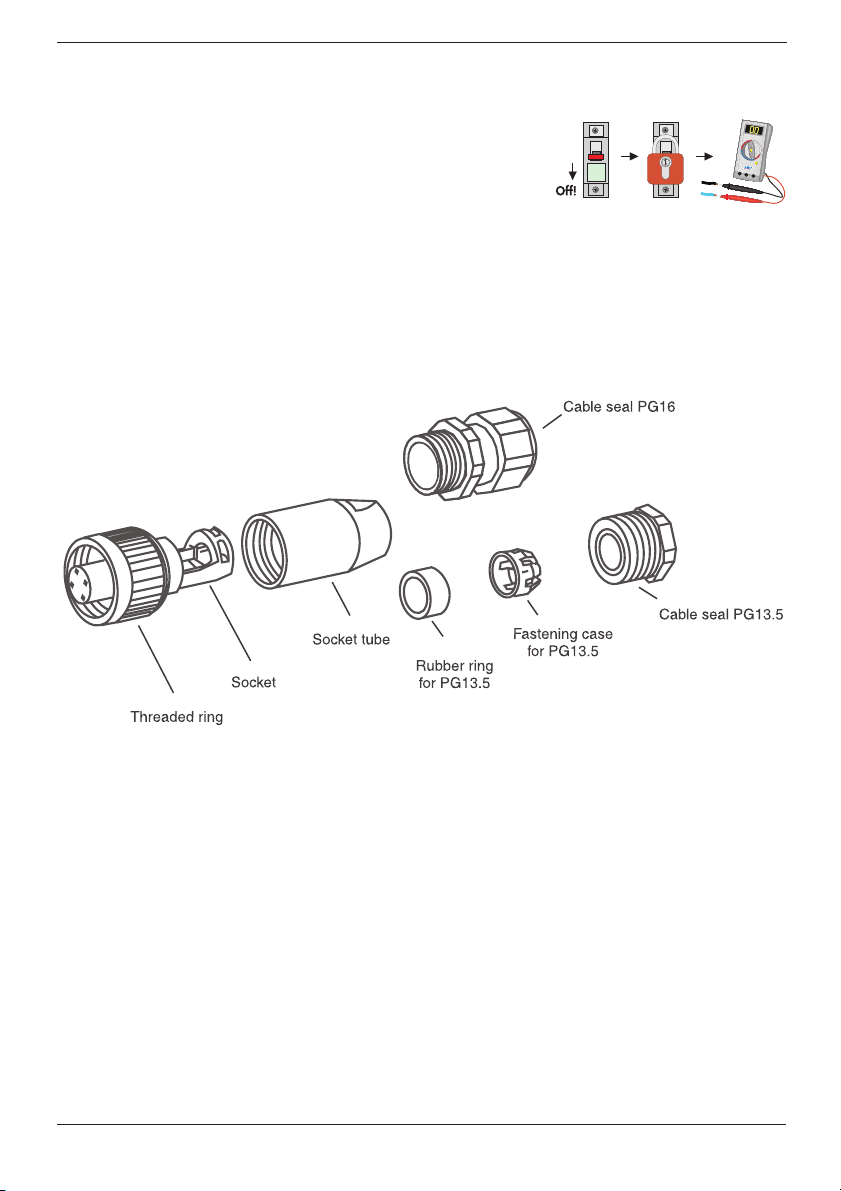
2. The AC connector is a round socket that is suitable to take
different cable diameters. A PG13.5 and a PG16 cable seal
are included with the AC connection socket. Check which
size is suitable for your AC connection cable.
3. Strip the insulation off the ends of the cable and connect the
cable to the AC socket as shown below.
4. Push the rubber ring into the fastening case.
5. Put the cable through the PG13.5 or 16 cable seal. Put the
cable through the fastening case with the rubber ring and
through the socket tube.
6. Connect the wires of the AC cable as follows:
• Protective Earth (PE) to the terminal with the „ground“ sym-
bol.
• Neutral wire to the terminal marked with „ 1“
• Phase L to the terminal marked with „2“
• The terminal marked with „ 3“ is not used.
7. Make sure that all wires are firmly connected.
8. Push the socket tube firmly onto the socket.
Before opening the Sunny Boy check
whether the AC output is safely isola-
ted from supply!
Installation Installation Guide
18 SMA Regelsysteme GmbH SB2800i-11:SE0504
9. For cables that require the PG16 gland: Tighten the bolt of
the PB16 gland.
10.The AC connector socket is now ready to use.
11.Seal the AC connector socket in case you do not insert it into
the Sunny Boy.
12.The AC connector socket can be inserted into the Sunny Boy
in case the Sunny Boy is already mounted in the correct posi-
tion. Remove the seal from the AC connector on the Sunny
Boy, insert the AC connector plug and tighten the seal.
Do not switch on the circuit breaker yet! The
Sunny Boy 2800i may only be connected to the
AC grid when the PV strings have been
connected and the device is tightly closed.
Table of contents


