Evenlite Lite-Minder User manual
By
Installation / Operation Manual - Emergency Lighting
Central Inverter System
IMPORTANT SAFEGUARDS
When using electrical equipment, basic safety precautions should always be followed
including the following:
READ AND FOLLOW ALL SAFETY
INSTRUCTIONS
A. Do not use outdoors
B. Do not mount near gas or electric heaters.
C. Use caution when servicing batteries. Battery acid can cause burns to skin and eyes. If
acid is spilled on skin or in eyes, flush acid with fresh water and contact a physician
immediately.
D. Equipment should be mounted in locations and at heights where it will not readily be
subjected to tampering by unauthorized personnel.
E. The use of accessory equipment not recommended by the manufacturer may cause an
unsafe condition.
F. Do not use this equipment for other than intended use.
This unit contains lethal voltages. There are no user serviceable parts inside. Only authorized
service personnel are to be used for service.
SAVE THESE INSTRUCTIONS
The installation and use of this product must comply with all national, federal, state, municipal
or local codes that apply. Please read this manual thoroughly before installing and operating
the Lite-Minder Central Inverter System.
For assistance please call technical service at 800-967-5573 and speak to a technician
during normal business hours (EST).
EVENLITE - Life Safety Lighting Solutions - 2575 Metropolitan Dr, Trevose, PA 19052 - www.evenlite.com
Lite-Minder
Pg. 1

Table of Contents
1.0 Introduction
1.1 Mechanical Design Features
1.2 Electrical Design Features
2.0 Receiving and Storage
2.1 Inspection
2.2 Storage
3.0 Installation
3.1 Location
3.2 Operating Environment
3.3 Ventilation
3.4 Mounting Guidelines
3.4.1 Clearance
3.4.2 Wall Mounting Hole Locations
3.4.3 Knockout Locations
4.0 AC Connections
4.1 Removing the Top Cover
4.2 Removing the AC Breaker/Terminal Block Cover
4.3 Installing the Input Wires
4.4 Installing the Output Wires
5.0 Battery and DC Connections
5.1 Battery Inspection
5.2 Battery Installation
5.3 DC Voltage of System
6.0 Start up and Shut down procedures
6.1 Start-up Procedure
6.2 Shut-down Procedure
7.0 Specifications
8.0 User Interface
8.1 Scrolling Display
8.2 METER
8.3 ALARM MENU
8.4 EVENT LOG
8.5 SETUP MENU
8.5.1 DATE/TIME
8.5.2 VTD
8.5.3 I-MON (OFF or ON)
8.5.4 I-MON (xx.xxA)
9.0 System Operation
9.1 Startup Mode
9.2 Battery Charging Mode
9.3 Switched Output
9.4 Battery Power Mode
10.0 Warranty
10.1 Technical Service and Support
10.2 Return Material Authorization (RMA)
11.0 Maintenance and Service
11.1 Battery Maintenance
11.2 Battery Replacement
Pg. 2
Page
3
3
3
4
4
4
5
5
5
5
5
5
6
8
9
9
10
10
10
12
12
12
13
14
14
14
15
16
16
16
17
18
18
18
18
19
19
19
19
20
21
21
22
22
22
23
23
24

1.0 Introduction
The Lite-Minder Central Inverter System integrates the latest inverter and microprocessor
technology to produce a Pure Sine wave power output intended for use in Emergency Lighting.
The Lite-Minder is very efficient. It typically has a steady state loss of just 2 percent of full load
while online which makes it ideal for energy saving and green initiatives. It is designed
specifically for emergency lighting from the ground up and meets the needs of all lighting loads
since it is a pure sine wave output. Lite-Minder was designed and developed by an Emergency
Lighting Manufacturer and is a culmination of market requirements that require high efficiency,
load compatibility, energy savings, low cost, and high quality.
Lite-Minder produces a Pure Sine wave and this is the ONLY method of power that will ensure
any lighting load will be powered safely, efficiently and effectively.
1.1 Mechanical Design Features
Batteries and electronics are contained in a single cabinet which makes installation very easy.
Mounting can be achieved on a wall or floor and there are electrical knock outs (EKO’s)
available on all surfaces. Quick access to the interior of the cabinet for battery inspection and
maintenance is accomplished by the removal of two screws which holds the front shroud.
Single module containing all electronics can be easily removed for upgrade or replacement.
This module concept makes maintenance and repair easier and more cost effective because
specialized training and knowledge in a Central Inverter System is not required.
1.2 Electrical Design Features
Through the use of Pulse Width Modulation (PWM) and the latest MOSFET technology, Lite-
Minder can produce a Pure Sine wave output which is compatible with all types of lighting
loads. A high crest factor of 4 is extremely beneficial for high inrush loads and also ideal for
bringing Normally Off lighting loads on from a cold start. The high crest factor also improves
the dynamic response so mixing Normally on and Normally Off loads together causes less
performance loss than traditional inverters. Since the active PWM regulation scheme produces
a very low THD waveform, the Lite-Minder can power up even the most demanding loads with
power factor capabilities ranging from 0.5 leading to 0.5 lagging.
There are three distinct outputs from the Lite-Minder which are Normally On, Normally Off and
the Switched Outputs. The Normally On Output is always present under normal utility power or
emergency power. The Normally Off Output is only present under emergency power so it is a
switched output when the Lite-Minder runs under emergency power.
The Switched Output is a user enabled output capable of switching Emergency Lighting loads
on and off making energy savings and green initiatives easy to accomplish. The switched
output is enabled by a switched command input signal of 120-277 VAC. Any output including
Normally On, Normally Off or the Switched Output is capable of producing full output power
and has no de-rating which means that 100 percent of the units rating can be driven from any
output. The switched output is also tied to the VTD function for HID applications having
Normally Off light sources. The batteries are charged by a temperature compensated charger
integrated into a bi-directional converter. A three rate charging scheme and bi-directional
converter topology ensures maximum float life and minimal ripple current on the batteries.
Pg. 3

2.0 Receiving and Storage
2.1 Inspection
The Lite-Minder Central Inverter and batteries are shipped separately. Upon arrival, please
inspect the contents to ensure that no shipping damage has occurred. This is especially
important with the batteries to ensure that there are no cracks or leaks. If any damage has
occurred, notify the shipping carrier immediately and submit a damage claim.
WARNING - Do not install damaged battery as this may cause an unsafe condition.
2.2 Storage
Storage before the installation is critical for the battery life expectancy and warranty. Store the
batteries indoors in a clean, dry, and cool location. Storage at higher temperatures will result in
accelerated rates of self-discharge and possible deterioration of battery performance and life.
WARNING– The maximum storage time from shipment to initial charge is 6 months for
batteries stored at ambient temperatures no warmer than 77°F (25°C). For storage
temperatures greater than 77°F (25°C), the batteries must be recharged one (1)
month sooner for every 5°F (3°C) increase above 77°F (25°C).
Storage Temperature Storage Time
32°F (0°C) to 50°F (10°C) 9 Months
51°F (11°C) to 77°F (25°C) 6 Months
78°F (25°C) to 92°F (33°C) 3 Months
Storage at high temperatures will result in accelerated rates of self-discharge and possible
deterioration of battery performance and life. Storage times exceeding the above may result in
plate sulfation, which may adversely affect electrical performance and expected life.
Failure to install and charge the batteries as noted VOIDS the battery’s warranty.
DANGER-A battery can present a risk of electrical shock and high short circuit
current.
Valve-regulated lead-acid (VRLA) batteries contain an explosive mixture of
hydrogen gas. Do not smoke, cause a flame or spark in the immediate are of
the batteries. This includes static electricity from the body. Use proper lifting
means when moving batteries and wear all appropriate safety clothing and
equipment.
Pg. 4

3.0 Installation
3.1 Location
NEC article 700 EMERGENCY CIRCUITS should be referenced for proper installation of a
Central Inverter System. Article 700 dictates that unit must be mounted in a permanent
location. Choose a cool dry place with normal ventilation and one which will allow easy access
for testing and maintenance. Avoid a location which could allow vandalism and tampering with.
Avoid areas that would prohibit visual contact with the heads up LED status displays.
3.2 Operating Environment
Choose a location that is controlled between 20 and 30 degrees C. for optimum battery life
and performance. Lite-Minder is UL listed between 20°C to 30°C (68°F to 86°F) because of
battery discharge performance results. Do not install in a wet or damp location. Do not install
in environments that will expose the unit to excessive temperatures like boiler rooms as this
will significantly depreciate battery life.
Heat is the determining factor of battery life. Every means should be made to keep the
batteries in an environment that keeps the batteries around 25 degrees C for rated battery life.
3.3 Ventilation
Choose a mounting location that is clean and dust free. Do not install in areas where there is
particulate from heavy industrial machinery, corrosive chemicals or welding and plasma
cutting environments, etc.
WARNING – Batteries for Light-Minder can weigh up to 60 pounds
each. Total system weight can be up to 160 pounds. Ensure that the
mechanical mounting means can support this weight.
3.4 Mounting Guidelines
3.4.1 Clearance
Lite-Minder is convection cooled and air ventilation is through the sides and up the top. Leave
at least 4 inches of clearance on the sides and top for proper air circulation.
WARNING - Never leave any objects lying on the top of the unit which
would prevent proper air flow. This blocking of air circulation may
result in an over-temperature fault during Battery Charging or Battery
Power mode depending upon ambient conditions.
Pg. 5
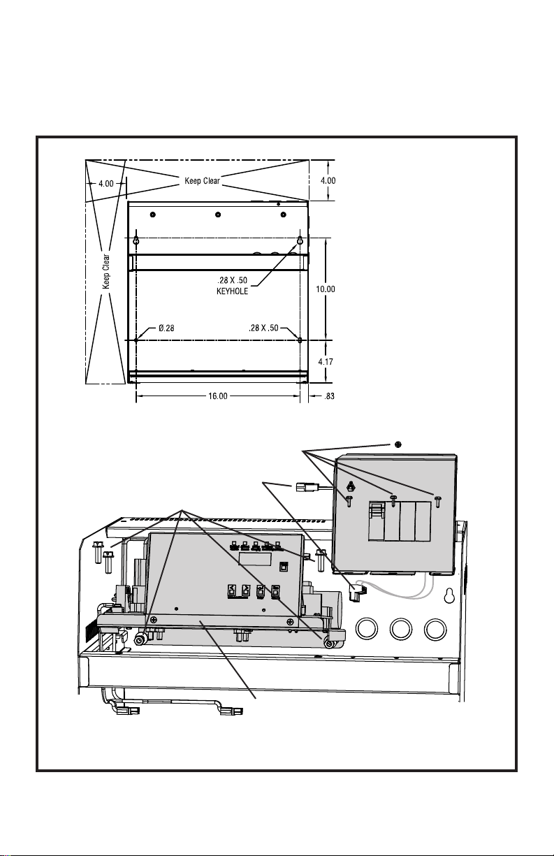
3.4.2 Wall Mounting Hole Location
Mounting holes are provided for Wall Mount purposes. The location of these holes are at the
back side of the cabinet and will accommodate ¼’mounting hardware. Four holes are provided
and all 4 should be used when wall mounting.
remove 3 screws and 2 nuts an washers
holding the gear tray
pull the Gear Tray forward
and lift up while supporting
from below
disconnect AC Input/Output connectors
and Installation Switch cable
remove 4 screws - remove the
AC Breaker/Terminal Block Assembly
Gear Tray
AC Breaker/Terminal Block
Assembly
Note:
Using the mounting holes
provided in the rear of the
enclosure requires removal
of the gear tray and AC
Breaker/Terminal Block
Assembly for access.
Note: See optional Wall Mounting Kit (next page)
Gear Tray and AC Breaker/Terminal Block Assembly Removal
Wall Mounting Dimensions
Pg. 6

Optional Mounting Kit for Wall or Strut Mounting
Bracket mounts to enclosure rear
panel with 3x 1/4-20 bolts
No unit dis-assembly is required
Enclosure Outline
Inverter hooks on to plate and is
secured by 2x 1/4-20 bolts in
battery compartment
Plate is fastened to
wall or struts (hardware
supplied by others)
2x 1/4-20 bolts
Rear conduit clearance holes
Mounting Plate Dimensions
Struts
Pg. 7
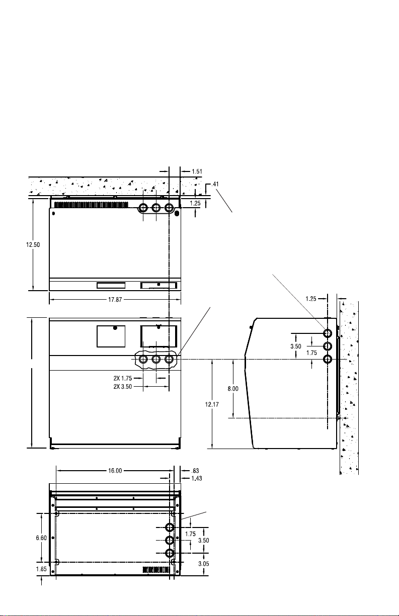
3.4.3 Knockout Locations
Electrical Knock Outs are provided on all surfaces of the Lite-Minder. Ensure all metal conduit
is secured and tightened creating a good connection to earth ground. Use an Ohm-Meter to
check that continuity between conduit and protective earth ground has been established.
At NO time is drilling allowed into the cabinet! Drilling causes metal filings to be deposited on
surfaces and could land on the Printed Circuit Boards and cause short circuits.
WARNING – Drilling into cabinet may void warranty if metal filings
causes unit failure.
Pg. 8
Space for Optional Mounting Kit
(see page 7)
Wall
Wall
bottom View
top view
right side view
front view
4x .28 dia. mounting holes
(floor mounting)
knockouts on
rear panel
12x double web
knockouts
.875/1.125 dia.
17.72
4.0 AC Connections
WARNING – Only qualified personnel that are familiar with AC and DC
installation techniques and codes (such as an electrician) should perform the
installation.
WARNING – The Lite-Minder contains lethal AC Voltages. Because of these
hazards, always shut down all sources of power before you install, maintain,
or service the unit.
WARNING – Remove all rings, watches, and other jewelry before doing any
electrical service or installation work. Always wear protective clothing and
appropriate personal protective equipment (PPE) that is suitable such as eye
protection when working near batteries.
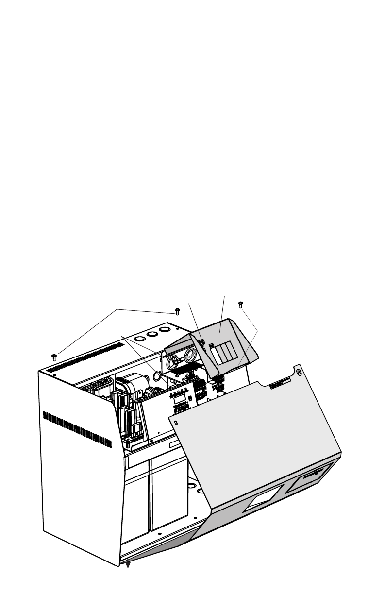
4.1 Removing the Top Cover
All the connections for the AC input and output are located on the top right side of the units’
enclosure. To access this wiring area, remove the top 2 screws that secure the units Top
Cover. After the two top screws are removed, simply slide the Top Cover forward and then
slide it down so that the bottom flange releases from the cabinets mating flange.
remove 2 screws - pull
cover forward and down
and back to remove
Installation Switch
disconnect
installation
switch remove screw and
lift off cover
AC Breaker/
Terminal Block Cover
Cover Removal
Inverter Cover
lift
Pg. 9

4.2 Removing the AC Breaker/Terminal Block Cover
There is a single screw that holds the AC Breaker/Terminal Block Cover securely to the
chassis. This cover conceals the wiring area and provides a safety cover so that fingers
cannot inadvertently touch live parts after installation. After removing this screw, simply lift the
cover up all the way until it is perpendicular and slide it forward so that the two flanges on the
cover release from the mating two slots on the chassis.
WARNING – Always re-install the AC Breaker/Terminal Block Cover to prevent
accidental contact with live wires during routine maintenance.
4.3 Installing the Input Wires
Once the Top Cover and Circuit Breaker Terminal Block Cover are removed:
1. Ensure that the incoming AC voltage to the Lite-Minder is the same voltage rating as the
unit.
2. Ensure that the feed breaker from the panel has at least the same breaker rating as the Lite-
Minder’s input breaker.
Once Feed Voltage and Breaker size is correct, connect the Utilities Feed Line voltage to the
Input Circuit Breaker. There will also be a dedicated position for Neutral, and Ground. Ensure
that the connections are tight by giving the wires a good pull and ensure that the wires are
secured into the blocks. Connection to these blocks will require a small flat bladed screw-
driver.
NOTE – AC Input and AC output wires must be run in separate conduit or raceways per
NEC ARTICLE 700. Please ensure all codes and standards are observed.
NOTE - Lite-Minder requires that the Neutral and Ground potential does not exceed 5 VAC
for proper function. Anything above 5 VAC typically indicates that there may be a
grounding issue or inadequate conductor size or continuity. This should be looked at
immediately as it could cause a safety concern.
NOTE – Neutral and ground should never be tied together anywhere in the Lite-Minder.
Always keep Neutral and Ground wires separate and ensure no shorts occur.
NOTE – Neutral connections in Lite-Minder are a “Pass Through’ which means Input and
Output Neutrals are directly connected.
NOTE – Never mix Neutrals on the building wiring(Non-Emergency) with the Emergency
wiring. Dedicated wiring is required by NEC code ARTICLE 700.
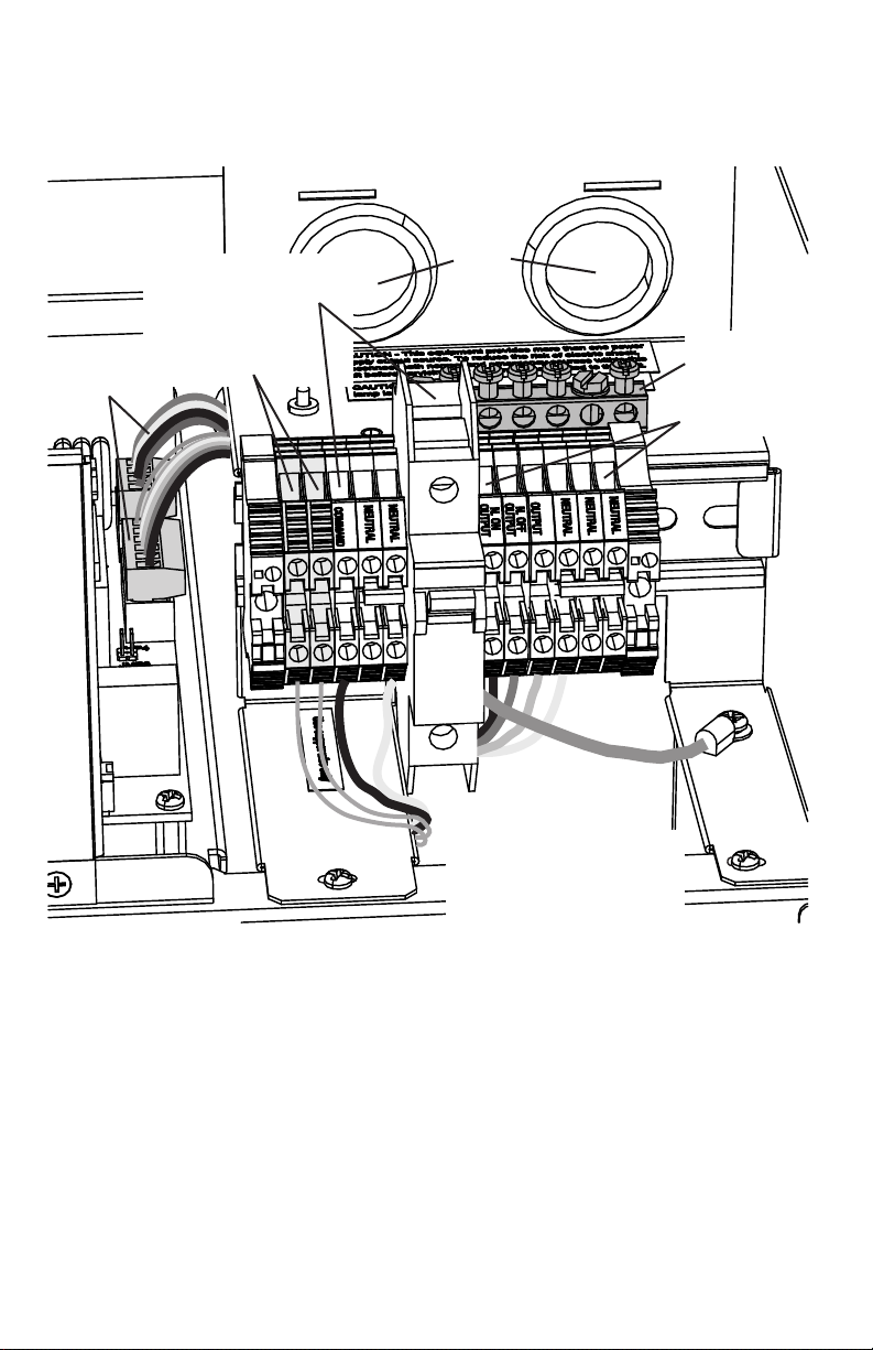
4.4 Installing the Output Wires
Connect the load wires to the terminal block labeled N. On, N. Off or Switched Outputs. There
will be dedicated terminal hook up positions for each Line, Neutral and Ground similar to the
AC Input section. Again, ensure that the connections are tight by giving the wires a good pull
and ensure that the wires are secured into the blocks. Connection to these blocks will require a
small flat bladed screwdriver. In the event that an output circuit breaker was supplied in the
unit, the load hot wire will be directly connected to the breaker. Load Neutral and Ground will
still connect to a terminal block.
Pg. 10
Pg. 11
LINE
OUTPUT
CONNECTIONS
INPUT
CONNECTIONS
GROUND BAR
POWER PCB
CONNECTIONS
OPTIONAL
SUMMARY ALARM
CONNECTIONS
WIRE
PORTS
Note: Up to three output
circuit breakers can be
mounted on the terminal
block rail
Standard AC Input/Output Panel
SWITCHED
SWITCHED

NOTE –“Wiring from an emergency source or emergency source distribution
overcurrent protection to emergency loads shall be kept entirely independent
of all other wiring and equipment, unless otherwise permitted” NEC ARTICLE
700 excerpt.
5.0 Battery and DC Connections
WARNING – Only qualified personnel that are familiar with AC and DC
installation techniques and codes (such as an electrician) should perform the
Installation.
WARNING – Remove all rings, watches, and other jewelry before doing any
electrical service or installation work. Always wear protective clothing and
appropriate personal protective equipment (PPE) that is suitable such as eye
protection when working near batteries.
WARNING - Batteries contain tremendous energy and can explode if short
circuited. Precautions should be taken to eliminate possible short circuits. Do
not install batteries until unit is completely mounted and secured in a
permanent location with all conduit and AC wiring connected.
5.1 Battery Inspection
Inspect the batteries for any physical damage such as cracks or any other sign of leaking
electrolyte. Batteries contain Sulfuric Acid which is highly corrosive. A leak from a battery will
cause an unsafe condition.
Each battery comes pre-connected with wire sufficient for the current of the system and has a
quick connect/dis-connect means by use of Anderson Power Pole connectors. These
connectors are mated together with the inverters pre terminated connectors for fail-safe
connection.
5.2 Battery Installation
Because the batteries come pre-terminated with connectors, installation is simply placing the
batteries on the inverter's bottom shelf and then connecting each batteries connector to the
mating connectors in the wiring harness.
Torque on all lugs to the batteries are 5 Newton Meters or 44 Inch Pounds.
NOTE – The top cover should already be removed from installing the AC Input
and Output wiring. Please refer to section 4.1 for Top Cover Removal.
Pg. 12

Battery Connection
5.3 DC Voltage of System
The systems DC battery voltage for all models of Lite-Minder is 24 VDC nominal. This voltage
is produced by connecting two batteries (each 12 VDC) in series.
All required cables are provided by the manufacturer and come pre-installed on the batteries.
The batteries connect to a wiring harness in a fail-safe manor to accomplish the system buss
requirements.
NOTE – Battery potential has galvanic isolation from AC potential. Any
battery voltage measurements must be made with both meter leads
connected to the battery terminals.
Unit Capacity
525 watt standard
325 watt standard
525 watt 2 Hr Run
325 watt 2 Hr Run
525 watt 20 Year
325 watt 20 Year
Replacement Batteries
Battery Assembly
(includes cable)
A310015 -1 or -2
A310016 -1 or -2
A310017
A310018
A310019 Pure Lead
A310020 Pure Lead
Red
Blk
Blu/Blk
Red/Blu
Battery 2 (positive) Battery 1 (negative)
Pg. 13
6.0 Start up and shut down procedures
Start-Up
After the AC input and output wires are connected and the batteries are properly installed, the unit is
ready to be started up. Start-up requires that the AC input be present. The unit will not start up
without AC input voltage.
Ensure that the incoming AC voltage is reaching the unit by turning on all feed circuit breakers. Once
AC input is verified, simply turn on the systems on/off switch located behind the removable circuit
breaker access door. Place the switch in the up position to on. The unit will go through a series of
relay clicks to verify proper connections and then go into the charge mode. The unit is now on-line
and ready. Verify that all load connections are operating within the specifications of the unit by
measuring AC currents on both the line and load and measure all neutral currents to ensure line and
neutral currents are the same.
Press the Test button on the front panel to verify that the normally off and switched output loads are
all operational and again measure currents.
If alarms occur during start-up, see section 8.3 for possible explanations. Also see section 9.1 for
Start-Up Mode explanations.
Shut-Down
To shut the system down, simply place the system on/off switch to the off position and place the
input circuit breaker and any optional output breakers to the off position.
If the unit is Shut-Down for a long duration please see Battery Storage Section 2.2 to ensure that the
batteries are not damaged from the effects of self-discharge and high ambient temperatures.
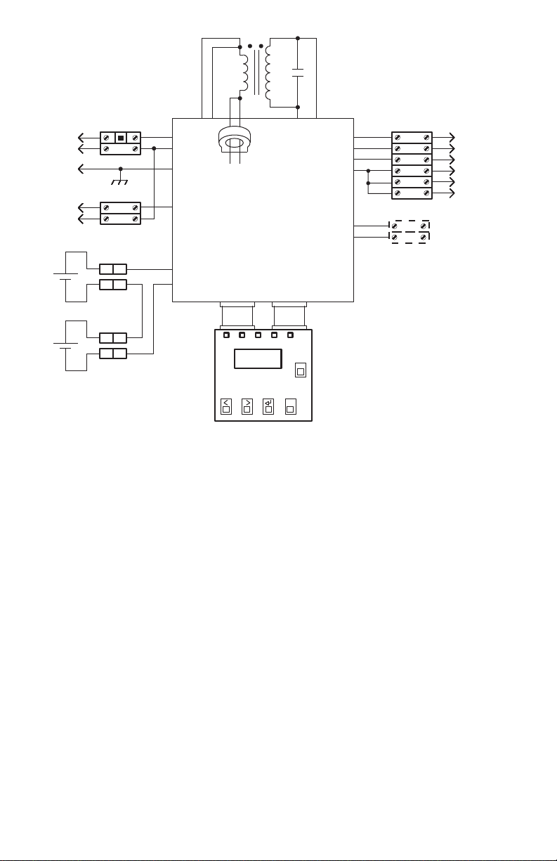
Wiring
Schematic
J1-2
J1-3
J1-4
TB1
TB2
J1-1
J6-1
J6-2
J6-3
J6-4
J6-5
J6-6
TB3
TB4
J4-2
J4-1
TB5
TB6
P2 P3
Display PCB
A250105
Power PCB
N. On out
A250104
N. Off Out
Switched Out
Neutral
Neutral
Neutral
Line
Neutral
Gnd
Switched Command
Input Signal
Neutral
Battery 1
Battery 2
T1
C1
Optional Summary
Blk
Alarm Terminals
Wht
Grn
Vio
Red
Blk
Blu
Red
Blk
Blk
Red
13.3v 120 /
277v
Blk
Blk
Blk
Blk
Wht
Blk
Blk
Brn
Blu
Wht
Red
Red
Wht
Blk (120 V)
Org (277V)
J2 J3
Pg. 14

7.0 Specifications
Input
Voltage 120 or 277 VAC model dependent
Current 5.8A (120V), 2.5A (277V) for 525 Watt Model
4.2A (120V), 1.8A (277V) for 325 Watt Model
Frequency 60Hz +/- 2 Hz
Protection Input Circuit breaker with fast acting KLK fuse in
series a for easy Selective Coordination to upstream feed breaker.
Power Factor 0.5 lead to 0.5 lag
Output
Voltage 120 or 277 VAC model dependent
Current 4.38A (120V), 1.9A (277V) for 525 Watt Model
2.7A (120V), 1.17A (277V) for 325 Watt Model
Frequency 60Hz +/- 0.02 Hz crystal controlled during
emergency mode
Overload 120 percent for 10 minutes, 400 percent for 200 mS
Transfer Time Adjustable 50mS or less than 2mS (slow or fast transfer)
Output Distortion Less than 3% THD
Crest Factor 4 for 525W model, 6.5 for 325W model
Load Power Factor 0.5 lead to 0.5 lag
Protection Optional circuit breakers
Output Types Normally On, Normally Off and Switched Output
Battery
Type Valve-Regulated sealed lead-calcium. Upgrade option available
Charger 3 rate with Temperature Compensation
Recharge Time 24 Hour recharge standard
Protection Automatic Low Voltage Disconnect (LVD) set at 1.67 VPC
Automatic restart upon utility return
Runtime 90 Minutes, Initial margin of 125 percent at 25 deg. C
DC Voltage 24 VDC Nominal, 2.27 VPC float, temperature compensated
DC Current 24 ADC Nominal
Environmental
Operating Temp 20 to 30 degrees Centigrade
Storage Temp -20 to 70 degrees Centigrade (Electronics)
0 to 40 degrees Centigrade (Batteries)
Relative Humidity <95 % (non-condensing)
Physical
Cabinet NEMA Type 1 enclosure, 16 AWG powder painted CRS
Cooling Natural Convection – No fans
Pg. 15

8.0 User Interface
The User Interface consists of a 4 button keypad and an 8x2 backlit LCD display. During
normal operation the LCD will scroll through meter functions and status. There are 5 heads-up
LED display indicators for system status that include Alarms, Battery Charging, Battery Power,
AC Present and Switched Output status.
8.1 Scrolling Display
The Root-Menu is a scrolling display that scrolls between Company Name and Model,
Operating Mode (System Start Up, Battery Charging or Inverter On), Faults, Output Voltage,
Output Current, Battery Voltage, Date and Time, Days, Events and Minutes.
To access any of the Menus (METER, ALARM, EVENT LOG and SETUP) simply press the
ENTER button. Pressing the left or right arrow in the scrolling display mode will advance or
retard the scroll. Pressing Escape in any of the Sub-Menu's will retard back one menu level.
Pressing Escape multiple times will always return the user to the Root-Menu.
8.2 METER
To enter METER functions from the Root-Menu, press the Enter key and METER will be the first
Sub-Menu. Press Enter again to enter the METER functions. Once in the METER menu, the
following functions are available by scrolling left or right:
V-OUT Output Voltage
I-OUT Current Output
V-BATT Battery Voltage
TEMP Ambient Temperature in Deg. C
DAYS Number of days the system has been on line
EVENTS Number of times the system has transferred to battery power
MINUTES Number of minutes the inverter has run on battery power
Test
Enter Escape
Switched
Load On
AC Input
Present
Battery
Charging
Emergency
Power On
Fault
(See Menu)
Esc
Test
display
Status LEDs
By
Lite-Minder
Pg. 16

8.3 ALARM MENU
To enter ALARM menu and see the active alarms, press the enter key from the scrolling menu.
Then press the right arrow key to get past METER and then press ENTER once the ALARM
menu is visible. Once in the ALARM menu you may see an active alarm present if the heads up
LED lamp is illuminated. If no alarms are active, the display will read NO FAULTS. The following
alarms are available through the diagnostics within the Lite-Minder inverter.
Start Up Faults:
BACKFEED This indicates that there is AC already at the output terminals
Most likely scenario is that the Lite-Minder was wired incorrectly
ROTATION This indicates that there is a wiring fault on the transformer
Most likely scenario is that if a PCB was replaced, there was a mis-
wire when re-connecting the transformer.
OVERLOAD This indicates that there is too much output or a short circuit load
connected.
MIS WIRE This indicates there is lack of AC power at the input
BATT LOW This indicates that the Batter Voltage is too low to start the unit up
Possible fault is that the battery is mis-wired, fuse is open or batteries are
dead
Faults While Lite-Minder is on Battery Charging:
AC FUSE Indicates a blown fuse on the input AC. Fuse location is on the PCB
CHARGER Indicates that the charger has malfunctioned
OVERLOAD Indicates that there is too much load connected
OVERTEMP Indicates that the FET’s Heatsink temperature has exceeded its limits
Faults While Lite-Minder is on Battery Power:
LOW VOUT Indicates that the inverter could not produce enough voltage to
support the load
FET O C Indicates that there was a severe overload that caused the crest factor
to be exceeded too many times and the inverter shut down to protect itself
from failure
LVD The inverter ran on battery until the Low Voltage Disconnect point
OVERLOAD There is too much load connected to the output
OVERTEMP Indicates that the FET’s Heatsink temperature has exceeded its limits
Pg. 17

8.4 EVENT LOG
To enter EVENT LOG and see any of the stored logs, press the enter key from the scrolling
menu, press the right arrow key to get past the METER, ALARM, and then press ENTER once
the EVENT LOG is visible. Once in the EVENT LOG menu you will have to use the left and right
arrow key to scroll to the desired event. When you enter for the first time the software always
takes you to the last event number. Once the event number is selected, you will have to use the
left or right arrow key again to view the following information:
EVENT Indicates the event number that data is being presented on
DAY Indicates the day that the event took place. This is a rolling day number so if the
event occurred on DAY 0001, it was on the first day the Lite-Minder was started up.
LENGTH Indicates how long the Lite-Minder ran on battery power. This is useful to indicate if
there was a power outage or just a glitch in AC power.
TEMP Indicates what the temperature of that event was in degrees Centigrade.
V-OUT Measurement of the output voltage during that event
I-OUT Measurement of the output current during that event
V-BATT Measurement of the battery voltage at the end of the event
This data in the EVENT LOG is very useful in determining several things. It keeps track of the
temperature for record keeping which is required for warranty purposes. It keeps track of the
battery voltage at the end of the discharge to indicate how deep the battery was discharged
and if it correlates to a healthy battery. The largest benefit of the log though is to keep record of
tests and events for Safety Inspectors so they can see that the unit is functional and has
performed discharges in accordance with NEC codes.
The Lite-Minder has the capability of storing the last 128 events. When the memory becomes
full, the over-write process is first in – first out. This means that event number 129 will over-
write event number one. The event number is kept sequential and its information is not lost so
event number 129 will remain number 129 and not get re-assigned to event number 1.
8.5 SETUP MENU
8.5.1 Date and Time
The Date and Time are adjusted by using the enter key to select which parameter you want to
set and then using the left and right key to change it. Once the parameter is set to the correct
number, press enter or escape to lock the new number in and return to scroll to the next
parameter. The parameters for date and time are:
Hour(24 hour format), Minute(Min), Month(Mon), Date , and Year.
8.5.2 VTD
The VTD (Variable Time Delay) feature is adjustable from OFF ( zero minutes) up to 15 minutes
in 1 minute increments. This function is useful if there is High Pressure Sodium, Metal Halide,
or Mercury Vapor High Intensity Discharge Lamps used for illumination. If these types of HID
lights are used, the variable time delay will keep the normally off and switched output lights
energized for the duration the VTD is set for. This allows time for the HID lights to re-strike after
cooling down. The factory default value for this function is OFF.
Pg. 18

8.5.2 I-MON (OFF or ON)
This feature is used for self- testing and self- diagnostics. If the I-MON is selected ON, the
output current will be compared against the I-MON stored current and if there is a difference by
more that 10 percent, the Lite-Minder will display a fault.
This feature is only functional when the Lite-Minder is under Battery Power. When the Lite-
Minder is in the Battery Charging mode, this function will not be active since it may require all
connected loads of Normally On, Normally Off and Switched Output to be connected. This
feature is Self-Testing, Self-Diagnostic and is only performed when the inverter is producing
power.
NOTE: If there are shunt relays or photo-sensors or any other means of load
shedding connected, this feature should not be used. The use of load shedding
devices may cause false alarms since the stored load current value is compared
against the actual load current value.
The factory default value for this function is OFF.
8.5.3 I-MON (xx.xx A)
This function is the stored current for the self-testing self-diagnostic feature. The xx.xx value
can be anywhere from 00.00 up to the maximum output current capability of the Lite-Minder.
To change this value, press ENTER at this menu and then there will be a display capable of
scrolling with the right arrow key that will read PRESS ENTER > TO UPDATE > I-MON VALUE.
If the ENTER button is pressed, the connected load current at the output of the Lite-Minder will
be stored as the new value.
It is important to note that the load current could be different under the different operating
modes of Battery Charging or Battery Power. This is due to the fact that Normally Off loads are
not energized and the Switched Output loads may or may not be energized when the Lite-
Minder is in the Battery Charging mode.
If there are Normally Off or Switched Output loads connected, you must set the value of I-MON
when the unit is in Battery Power. To do this, simply press the TEST button or Disconnect AC
power to cause the Lite-Minder to enter Battery Power mode. Once in Battery Power mode, all
connected loads are energized.
9.0 System Operation
9.1 Start-Up Mode
When the Lite-Minder is first turned on, it goes through a sequence of self-tests to ensure
proper connections and it checks for faults that may be present. This is the System Start Up
mode and it must qualify several things before advancing to go into the Battery Charging
mode.
Pg. 19

There will be two distinct clicks of relays as it goes through the self-check sequence. These
relay clicks are the Lite-Minder turning on the output relays to check if any voltages are present
and then tickling the output with a small voltage to see if short circuits or overloads are
present.
The faults that are checked for during start-up mode are:
BACKFEED – This is when AC voltages are present at any of the outputs. If there are AC
voltages present at any of the outputs, it means that there is a mis-wire and the utility AC
power is being back-fed into the inverter.
ROTATION – This fault would occur if the module was replaced and re-connected improperly.
The Phase Rotation diagnostic energizes the inverter and looks for output voltages out of
regulation.
BATT LOW – This fault would occur if the DC voltage at the power PCB is too low. Possibilities
for this fault to occur are blown DC fuse on the power PCB, Battery wiring incorrect or battery
voltages too low to start the system up without a failure.
OVERLOAD – This fault would occur if the connected load exceeds that of the rating of the
Lite-Minder. This check is performed by tickling the output to a low voltage for one cycle and
looking for overcurrent faults. This diagnostic features connects all the outputs such as the
Normally Off and the Switched Output.
MISWIRE – This fault would occur if the AC input voltage is not within specification. For
example if the unit is a 277V model and only 120V was connected, a MISWIRE fault would
occur. Conversely if a 120V model had 277 VAC connected, a MISWIRE fault would occur.
Also if no AC voltage was applied to the input, a MISWIRE would occur.
After all the Start-Up diagnostics are performed, the Lite-Minder is OK to proceed to the
Battery Charging mode.
9.2 Battery Charging Mode
The Battery Charging mode is where the system will remain for 99.9+ percent of its life. In
this mode, AC power is being passed through to the units output and subsequently its loads
and the batteries are keeping a float charge. The charger is floating at 2.27 Volts per Cell (VPC)
and is temperature compensated to 4mV per deg. C (per cell), centered at 25 degrees C.
For higher temperatures, the float voltage would go down and for lower temperatures, the float
voltage would go up.
The Lite-Minder nominal DC battery voltage is 24 VDC. The float voltage is 27.2 VDC (2.27
VPC) and the LVD voltage is 20.5 VDC (1.67 VPC).
Float voltage varies with temperature, LVD voltage is fixed.
Pg. 20
Table of contents
Other Evenlite Inverter manuals


Popular Inverter manuals by other brands

Mitsubishi Electric
Mitsubishi Electric FR-E500 Series instruction manual

Silicon Laboratories
Silicon Laboratories Si5332-AM1 Reference manual

Huawei
Huawei SUN2000-33KTL-US quick guide

Micro Innovations
Micro Innovations NBP150S Quick installation guide

Joy-it
Joy-it JDS6600 manual

actuant
actuant Mastervolt SunMaster CS15TL RP User and installation manual


