SMA Enwitec Sunny Island 4.4M User manual

engineering with innovations
MANUAL
Automatic Transfer Switch for the SMA Flexible Storage System
"BATTE Y BACKUP DIST IBUTION" within Battery Backup Function
- SUNNY ISLAND 4.4M/6.0H/8.0H
- Sunny Home Manager or SMA Energy Meter

18_06_07_Battery Backup Distribution_10010371_ENG_V1.8 Seite -2- von -38-
TABLE OF CONTENTS
1. About this guidance ............................................................................................................................... 4
1.1 Scope of application .......................................................................................................................... 4
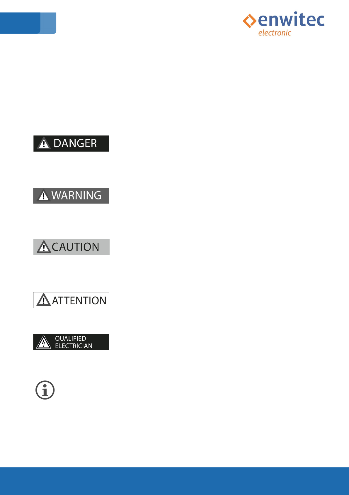
1.3 S mbols used ..................................................................................................................................... 5
2. Safet ......................................................................................................................................................... 6
2.1 Appropriate Usage ............................................................................................................................. 6
2.2 Safet Instructions ............................................................................................................................. 7
2.3 S mbols used on the t pe label ......................................................................................................... 8
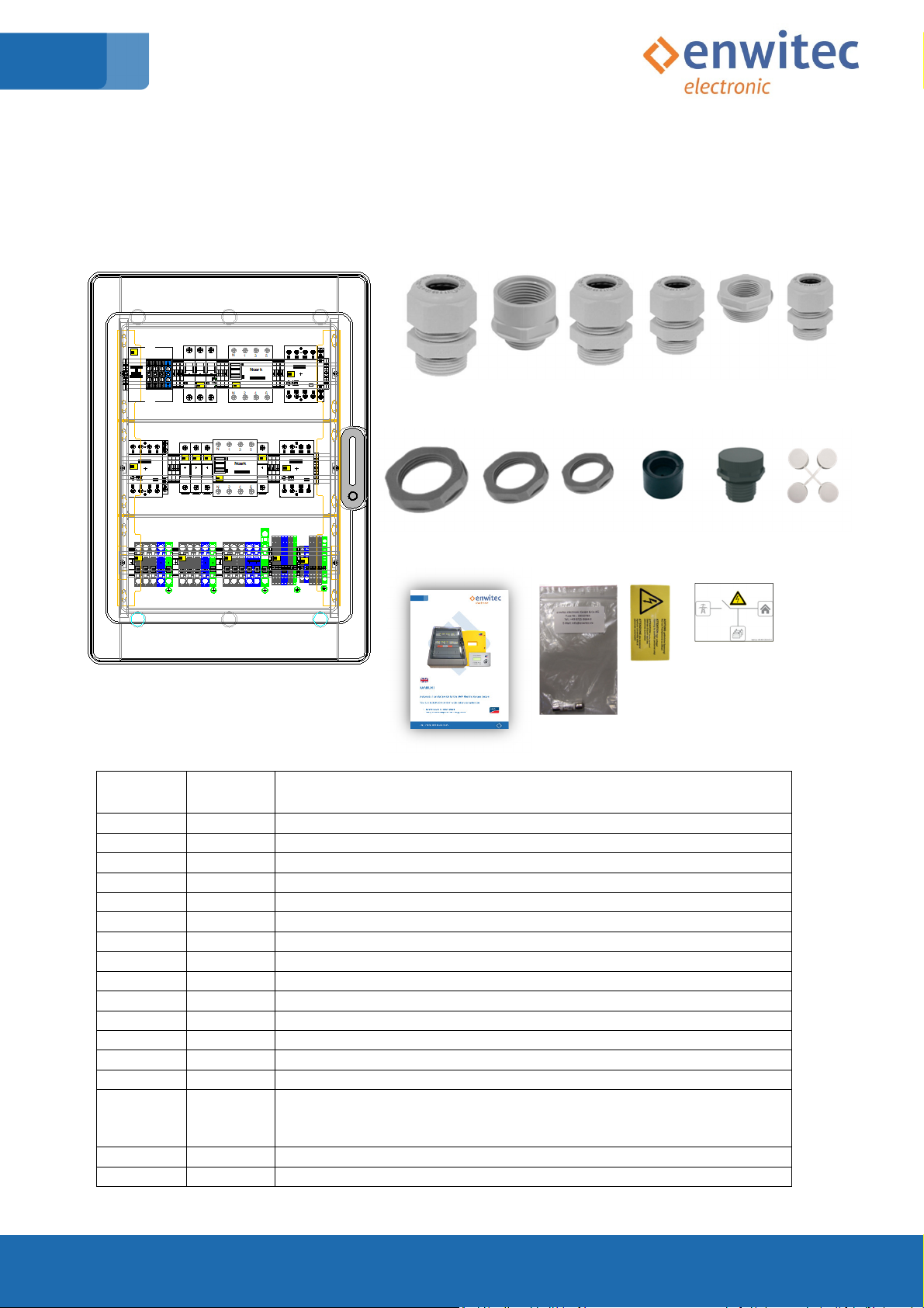
3. Scope of deliver ....................................................................................................................................... 9
3.1 Single-Phase Batter Backup Distribution (all-pole disconnection) .................................................. 9
3.2 Three-Phase Batter Backup Distribution (all-pole disconnection) ................................................ 10
4. Electrical Connection ............................................................................................................................... 11
4.1 Installation Energ Meter / Home Manager ................................................................................... 11
4.2 Single-Phase Distribution – all pole disconnection ......................................................................... 12
4.2.1 Circuit diagram – Single-Phase automatic transfer switch ...................................................... 12
4.2.2 S stem integration – Single-Phase – automatic transfer switch ............................................. 13
4.3 Three-Phase Distribution – all pole disconnection .......................................................................... 14
4.3.1 Circuit diagram – Three-Phase automatic transfer switch ...................................................... 14
4.3.2 S stem integration – Three-Phase automatic transfer switch ................................................ 15
5. Mounting the Batter Backup Distribution ............................................................................................. 16
5.1 Selecting the mounting location ...................................................................................................... 16
5.2 Installation clearances ..................................................................................................................... 17
5.3 Dimensions and Cable Entr ............................................................................................................ 18
5.3.1 Dimension and Fastening ........................................................................................................ 18
5.3.2 Cable entr – Single-Phase Batter Backup Distribution ......................................................... 19
5.3.3 Cable entr – Three-Phase Batter Backup Distribution ......................................................... 20
6. Connection compartment – la out terminals ......................................................................................... 21
6.1 Single-Phase Batter Backup Distribution ....................................................................................... 21
6.2 Three-Phase Batter Backup Distribution ....................................................................................... 22
7. Protective Conductor Connections (PE) .................................................................................................. 23
8. Phase coupling within Single-Phase „IPC“ version ............................................................................. 25
9. Connecting the grid – Main Suppl ...................................................................................................... 26
10. Connecting the Distribution Board (Load/PV) ................................................................................ 26

18_06_07_Battery Backup Distribution_10010371_ENG_V1.8 Seite -3- von -38-
10.1 Island-Mode (Backup Function) ....................................................................................................... 26
10.2 Grid-mode ................................................................................................................................... 27
11. Connecting the Sunn Island‘s ......................................................................................................... 28
11.1 Terminal Block X3 ...................................................................................................................... 28
11.2 Terminal Block X4/X5....................................................................................................................... 28
12. Speedwire-connection – Home Manager/Energ -Meter .............................................................. 29
13. Initial Operation ................................................................................................................................. 29
14. Disconnect from voltage ................................................................................................................... 31
15. Maintenance and cleaning (spare-fuse) .......................................................................................... 32
16. How to stock the Batter Backup Distribution ............................................................................... 33
17. Disposal .................................................................................................................................................... 33
18. Technical Data .................................................................................................................................... 34
18.1 Single-Phase BBDAP .................................................................................................................. 34
18.2 Three-Phase BBDAP .................................................................................................................. 35
19. EC Declaration of Conformit ........................................................................................................... 36

18_06_07_Battery Backup Distribution_10010371_ENG_V1.8 Seite -4- von -38-
1. About this guidance
1.1 Scope of application
The following instructions are valid for all enwitec electronic GmbH & Co. KG produced “Batter
Backup Distributions”, used in accordance with the recommendations of
SMA Solar Technology AG - Sonnenallee 1 34266 Niestetal - Germany
Please note that ou have also to fulfil the corresponding SMA paperwork, like
• Installation guide - Sunn Island 4.4M/6.0H/8.0H
• SMA Flexible Storage documentation
• Planning guideline
• Quick reference guide
T pe designations (enwitec electronic - matchcode) Batter Backup Distributions
3PH IPC SMA BBDAP 20KW 1PH PREP UK 1.0
version-number
national specifics
version "PREP": prepared for
“Energ Meter” / “Home Manager”
Sunn Island's configuration
1PH: Single Phase
3PH: Three Phase
Max. thermal power
[kW]
Product designation
„Batter Backup Distribution incl.
All Pole Disconnection“
Compatible to SMA S stems
Meets onl the 1PH (Single Phase)
IPC: „Inclusive of Phase Coupling“
EPC: “Exclusive of Phase Coupling”
1PH: single-phase backup distribution
3PH: three-phase backup distribution

18_06_07_Battery Backup Distribution_10010371_ENG_V1.8 Seite -5- von -38-
1.2 Target group
This guide is intended to professional electrician! The activities described in this guide ma onl be
performed b qualified persons!
1.3 Symbols used
"Danger" indicates safet advice which, if not observed, will result immediatel in death or severe
personal injur !
"Warning" indicates safet advice which, if not observed, ma result in death or severe personal
injur !
"Caution" indicates safet advice which, if not observed, ma result in light or medium personal
injur !
"Attention" indicates safet advice which, if not observed, ma result in material damage!
"Qualified electrician" indicates work that ma onl be performed b a certified electrician.
"Info" indicates important information!

18_06_07_Battery Backup Distribution_10010371_ENG_V1.8 Seite -6- von -38-
2. Safety
2.1 Appropriate Usage
The „Batter Backup Distribution“ is an automatic transfer switch, suitable to the SMA „Flexible
Storage S stem“, functionall in communicating to:
- SI 4.4M-12 / SI 4.4M-13 (Sunn Island 4.4M) from Firmware 1.00.xx.R
- SI 6.0H-12 / SI 6.0H-13 (Sunn Island 6.0H) from Firmware 1.00.xx.R
- SI 8.0H-12 / SI 8.0H-13 (Sunn Island 8.0H) from Firmware 1.00.xx.R
- in combination with either
HM-20 (Sunn Home Manager 2.0) from Firmware 2.00.00.R
or
EMETER-20 (SMA Energ Meter) from Firmware 2.0.15.R
The Sunn Island S stem controls this automatic transfer switch (hereinafter called „Batter
Backup Distribution“ or shortened „BBD“) and creates an island network in case of main power
blackouts.
The Batter Backup Distribution does an all-pole disconnection and isolates the PV-S stem and the
load to the public network in a safe wa .
The Batter Backup Distribution is onl certified for TT- and TN-S grids!
Basicall , ou ma onl use the Batter Backup Distribution within the SMA „Flexible Storage
S stem“ in combination with SMA – Sunn Island 4.4M/6.0H/8.0H. Consult the corresponding SMA
paperwork (planning guidelines, installation-guides and all the other documents, which are
applicable for our countr and project).
Within a 3-phase s stem ou have to do a master/slave configuration of the Sunn Island’s. The
master is doing all the switching operations and controls the contactor’s activities. For more
details ou have to stud the SMA paperwork!
Do not exceed the maximum power input and connection power. Please note accordingl the
technical specifications of the various t pes (at chapter 18).
Do not use the Batter Backup Distribution for purposes other than those described here.
Alternative uses, modifications and the installation of components void the warrant claims and
operation permit.

18_06_07_Battery Backup Distribution_10010371_ENG_V1.8 Seite -7- von -38-
2.2 Safety Instructions
Electric shock due to high voltages in the Batter Backup Distribution when connecting the device!
Death or serious injuries!
All work on the Batter Backup Distribution must be performed b a qualified
personnel.
Work on the Batter Backup Distribution should onl be carried out as described
in this manual.
Observe all specified safet precautions
Construction and design of the Batter Backup Distribution is due to user-friendl handling of
circuit breakers, fuse holder and RCCB’s (residual current operated circuit breakers).
In addition (if the SMA Energ -Meter or the SMA Home Manager is included) ou are able to
notice different operational state of the s stem, shown b the LED’s.
Please consider the relating SMA Original instructions of the Energ -Meter or Home Manager.

18_06_07_Battery Backup Distribution_10010371_ENG_V1.8 Seite -8- von -38-
2.3 Symbols used on the type label
Symbol
Definition
It is not
allowed to dispose the Batter Backup Distribution in the
household garbage!
CE
-
Declaration
Declaration, that the Batter Backup Distribution meets all the mandator
european standards.
Protection class II
The protection of the Batter Backup Distribution against electric shock is secured
due to a reinforced insulation.
no s mbol
Protection rating IP65 (Ingress Protection Rating)
The Batter Backup Distribution is either protected against dust tight and water
jets (IP65)or protected against solid foreign objects of ≥1 mm diameter and water
splashing on all sides (IP44)
no s mbol
m
ax.
ambient t
emperatur
e
(t
a
) [°C
Up to this ambient temperature ou ma use the Batter Backup Distribution.
no s mbol
Rated voltage
[V
Do not use the Batter Backup Distribution in other than this voltage range!
no s mbol
Rated frequency
[Hz
Do not use the Batter Backup Distribution in other than this frequenc range!
no s mbol
Rated power
[kW
Do not connect more input- or distribution power!
no s mbol
Peak
–
Input current
[A
You may use the Battery Backup Distribution up to this peak-input current!
no s mbol
IEC/EN
–
Standard
The Batter Backup Distribution fulfils:
IEC/EN61439-1 "Low-voltage switchgear and controlgear assemblies"
IEC/EN61439-2 "Power switchgear and controlgear assemblies"
IEC/EN61439-3 "Distribution boards intended to be operated b ordinar
persons (DBO)

18_06_07_Battery Backup Distribution_10010371_ENG_V1.8 Seite -9- von -38-
3. Scope of delivery
3.1
Single-Phase Battery Backup Distribution (all-pole disconnection)
A B C D E F G
H I J K L M
N O P Q
p
osition
number
component
A 1 Batter Backup Distribution 1PH
B 2 Cable gland M40 x 1,5 (clamping range Ø 16 – 28mm)
C 2 Enlargement adaptor -M32 to M40-
D 3 Cable gland M32 x 1,5 (clamping range Ø 13 – 21mm)
E 2 Cable gland M25 x 1,5 (clamping range Ø 9 – 17mm)
F 1 Reduction adaptor -M20 to M12- (equalising membrane)
G 5 Cable gland M20 x 1,5 (clamping range Ø 6 – 13mm)
H 3 Locknut M32
I 2 Locknut M25
J 6 Locknut M20
K 1 Special sealing insert (CAT 5e cable „RJ45 Plug“ -M25-)
L 1 Equalising membrane
M 1 Cover caps for fastening screws
N 1 Installation Manual (this document) 10010371
O 3 Ferrule-fuse 10x38mm (either Littelfuse #KLKD-1A; Fast Acting
or Bussmann #KTK-1A; Fast Acting)
2 pcs. inserted (Fuse-holders); 1 pc. as a spare-part
P 1 Warning-label “high voltage”
Q 1 Label - image "with reference to an island mode s stem abilit "

18_06_07_Battery Backup Distribution_10010371_ENG_V1.8 Seite -10- von -38-
3.2
Three-Phase Battery Backup Distribution (all-pole disconnection)
A B C D E F G
H I J K L
M N O P
p
osition
number
component
A 1 Batter Backup Distribution 3PH
B 2 Cable gland M40 x 1,5 (clamping range Ø 16 – 28mm)
C 2 Enlargement adaptor -M32 to M40-
D 5 Cable gland M32 x 1,5 (clamping range Ø 13 – 21mm)
E 2 Enlargement adaptor -M25 to M32-
F 2 Cable gland M25 x 1,5 (clamping range Ø 9 – 17mm)
G 7 Cable gland M20 x 1,5 (clamping range Ø 6 – 13mm)
H 3 Locknut M32
I 4 Locknut M25
J 7 Locknut M20
K 1 Special sealing insert (CAT 5e cable“RJ45 Plug“ -M25-)
L 1 Cover caps for fastening screws
M 1 Installation Manual (this document) 10010371
N 5 Ferrule-fuse 10x38mm (either Littelfuse #KLKD-1A; Fast Acting
or Bussmann #KTK-1A; Fast Acting)
4 pcs. inserted (Fuse-holders); 1 pc. as a spare-part
O 1 Warning-label „high voltage“
P 1 Label - image "with reference to an island mode s stem abilit "

18_06_07_Battery Backup Distribution_10010371_ENG_V1.8 Seite -11- von -38-
4. Electrical Connection
4.1 Installation Energy Meter / Home Manager
Instead of the Energ Meter / Home Manager, screw terminals are used as placeholders.
An Energy Meter / Home Manager is not included in the scope of delivery and must be
retrofitted!
The terminals are capable of carr ing currents, whereb the basic function oft he automatic
transfer switch is given. Thus, the automatic transfer switch can alread be connected and tested
without Energ Meter / Home Manager.
During installation, note the positioning of the Energ Meter / Home Manager to the cover strips
of the distribution board.
When installing the Energ Meter / Home Manager, observe the maximum permissible torque of
2.0 Nm!
Z1
1
3 5
2 4 6 8
1
3 5
2 4 6 8
Placeholder
for
E-Meter /
Home
Manager

18_06_07_Battery Backup Distribution_10010371_ENG_V1.8 Seite -12- von -38-
4.2 Single-Phase Distribution – all pole disconnection
4.2.1 Circuit diagram – Single-Phase automatic transfer switch

18_06_07_Battery Backup Distribution_10010371_ENG_V1.8 Seite -13- von -38-
4.2.2 System integration – Single-Phase – automatic transfer switch

18_06_07_Battery Backup Distribution_10010371_ENG_V1.8 Seite -14- von -38-
4.3 Three-Phase Distribution – all pole disconnection
4.3.1 Circuit diagram – Three-Phase automatic transfer switch

18_06_07_Battery Backup Distribution_10010371_ENG_V1.8 Seite -15- von -38-
4.3.2 System integration – Three-Phase automatic transfer switch

18_06_07_Battery Backup Distribution_10010371_ENG_V1.8 Seite -16- von -38-
5. Mounting the Battery Backup Distribution
5.1 Selecting the mounting location
risk of explosion or fire during the installation of the device in
nonpermissible areas, death or serious burns. Despite careful
engineering, electrical devices can cause fires!
● Do not mount the device on flammable construction materials.
● Do not mount the device near highl flammable materials.
● Do not mount the device in potentiall explosive areas.
Mount on a solid surface
The mounting location and method must be suitable for the weight and dimensions
The mounting location must be accessible at all times!
climatic conditions must be in compliance to the specification (Look at
chapter -18-)
The device ma not be exposed to direct sunlight and weathering!
The mounting location has to be protected against splashing water!
You have to fulfil the requirements of the network operator!
Installation position

18_06_07_Battery Backup Distribution_10010371_ENG_V1.8 Seite -17- von -38-
200mm
200mm
4
00mm
1.200mm
200mm
5.2 Installation clearances
Minimum distances

18_06_07_Battery Backup Distribution_10010371_ENG_V1.8 Seite -18- von -38-
5.3 Dimensions and Cable Entry
5.3.1 Dimension and Fastening
values in [mm]
Select the correct mode of mounting, depending on the mounting surface, for example 4 x
expansion anchor „S8“ + 4 x chipboard screw Ø5.5
+
Fixing-holes
4 x oblong-holes Ø 5.5

18_06_07_Battery Backup Distribution_10010371_ENG_V1.8 Seite -19- von -38-
5.3.2 Cable entry – Single-Phase Battery Backup Distribution
recommendation: Take the knockouts at the bottom
type terminal block cable (e.g.)
M40 X1 alternativel 4 x 16mm
2
+ enlargement adaptor X2 5 x 16mm
2
M32 X1 4 x 16mm
2
X2 5 x 16mm
2
X3 3 x 10mm
2
M25 speedwire-cable -CAT 5/7e-
(special sealing) (E-Meter/Home-Manager)
M25 X5 3 x 6mm
2
M20 X4 – 2x (L1/N + 1/2) 3 x 1,5mm
2
X5 (1/2) 3 x 1,5mm
2
X5 (3/4) 4x2x0,8mm
2
(e.g. J-Y(St)Y Lg)*
PE
1 x 16mm
2
M12 equalising membrane – mount on reduction-
adaptor M20!)
* shielded cable

18_06_07_Battery Backup Distribution_10010371_ENG_V1.8 Seite -20- von -38-
5.3.3 Cable entry – Three-Phase Battery Backup Distribution
recommendation: Take the knockouts at the bottom
Enlargement adaptors -M25/M32-
type terminal block cable (e.g.)
M40 X1 alternativel 4 x 16mm
2
+ enlargement adaptor X2 5 x 16mm
2
M32 X1 4 x 16mm
2
X2 5 x 16mm
2
X3 (3x) 3 x 10mm
2
M25 speedwire-cable -CAT 5/7e-
(special sealing) (E-Meter/Home-Manager)
M25 X5 3 x 6mm
2
M20 X4 – Master 2x(L1/N + 1/2) 3 x 1,5mm
2
X4 – Slaves 2x(L2/N + L3/N) 3 x 1,5mm
2
X5 – Master (1/2) 3 x 1,5mm
2
X5 – Master (3/4) 4 x 2 x 0,8mm
2
(e.g. J-Y(St)Y Lg)*
PE
1 x 16mm
2
* shielded cable
This manual suits for next models
8
Table of contents
Other SMA Switch manuals