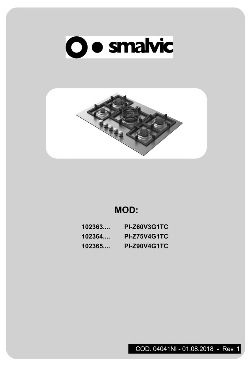
Smalvic 1023840400 User manual

MANUALE
USO E MANUTENZIONE
INSTRUCTIONS
FOR USE

Etichetta dati caratteristici del prodotto
Rating plate of the product
Informazioni strettamente condenziali.
Tutti i diritti sui contenuti di questo documento sono riservati.
È vietato copiare, utilizzare, distribuire anche parzialmente o mettere altrimenti in circolazione
tali informazioni, salvo espressa autorizzazione del produttore.
Le violazioni saranno perseguite ai sensi di legge.
Strictly condential information
All rights on the contents of this document are reserved.
The copying, use, distribution, even partial, or otherwise putting said information
into circulation without explicit authorisation from the manufacturer, is strictly forbidden.
Any violations will be prosecuted according to the law.

PIANO COTTURA ELETTRICO DA INCASSO
Libretto istruzioni per: Installazione - Uso - Manutenzione
Istruzioni originali
ELECTRIC BUILT-IN HOB
Operating instructions for: Installation - Use - Maintenance
Translate of the original instruction
Man. L001_012
Rev. 00_07/2018
IT
GB
Leggere attentamente le presenti istruzioni prima del primo impiego
Read this operator manual carefully before the rst use


IT
INDICE ARGOMENTI
INSTALLAZIONE
Istruzioni per l’incasso dei mobili 1.1
Avvertenze 1.2
Collegamento elettrico 1.3
USO
Funzionamento del piano cottura 2.1
Accensione delle zone di cottura 2.2
Spegnimento delle zone di cottura 2.3
Visualizzazioni display: note - errori - allarmi 2.4
Altre Funzioni 2.5
Avvertenze 2.6
MANUTENZIONE
Manutenzione e pulizia 3.1

6/ IT
MANUALE DI UTILIZZO
1.1 Istruzioni per l’incasso nei mobili
L’apparecchio può essere incassato in tutti i tipi di mobili le cui pareti resistano
ad una sovratemperatura di almeno 70 °C oltre a quella ambiente (EN 60335
- 2 - 6). Evitare di installarlo in prossimità di materiali inammabili ad esempio
tendaggi, canovacci, ecc.
Settore di separazione Apertura del mobile
INSTALLAZIONE
825 480
4
510 900
50

7/ IT
MANUALE DI UTILIZZO
1.2 Avvertenze
L’eventuale presenza di un pensile al di sopra del piano di cottura deve preve-
dere una distanza minima dal top di 600 mm. Per evitare eccessivi surriscal-
damenti, anche in assenza di un forno sottostante, é necessario prevedere un
settore di separazione, almeno della dimensione del foro di incasso.
Posizionare sul perimetro del piano l’apposita guarnizione sigillante (in dotazio-
ne) avendo cura che le estremità combacino senza sormontarsi.
Introdurre il piano nell’apertura del mobile curandone la centratura.
Fissare il piano al mobile con le apposite stae di ssaggio.
INSTALLAZIONE

8/ IT
MANUALE DI UTILIZZO
1.3 Collegamento elettrico
Il collegamento elettrico deve essere eettuato solamente da personale
qualicato a conoscenza delle norme di installazione in vigore.
L’apparecchio è predisposto per il funzionamento in corrente alternata,
alla tensione indicata sulla targhetta “dati caratteristici” riportata a ne
libretto e sul prodotto (vedere anche l’eventuale schema di collegamen-
to sul prodotto).
Nel caso di collegamento diretto alla rete, è necessario interporre tra
l’apparecchio e la rete un interruttore omnipolare con una distanza di
apertura dei contatti che consente la disconnessione completa nelle
condizioni delle categoria di sovratensione III conformemente alle rego-
le di installazione. Il lo di terra giallo/verde non deve essere interrotto
da tale interruttore.
Il cavo di alimentazione deve essere H05RR-F o di categoria superiore
(lista sezioni nella tabella seguente) e deve essere posizionato in modo
che in nessun punto possa raggiungere una temperatura superiore di
50°C a quella ambiente.
MAX POTENZA SEZIONE CAVO mm2
no a 16 A 1,5 mm2
no a 25 A 2,5 mm2
no a 32 A 4 mm2
Prima di eettuare il collegamento controllare che l’impianto di alimen-
tazione sia munito di collegamento di terra ecace e rispondente alle
normative in vigore e che la presa di corrente o l’interruttore omnipolare
sia facilmente raggiungibile ad apparecchio installato.
Il conduttore di terra (giallo/verde) collegato al morsetto del prodotto
deve essere più lungo degli altri.
Il produttore declina ogni responsabilità nel caso le norme in vigo-
re non vengano rispettate.
INSTALLAZIONE

9/ IT
MANUALE DI UTILIZZO
2.1 Funzionamento del piano cottura
Il piano è dotato di zone cottura ad induzione che si caratterizzano per ecien-
za e risparmio energetico. Quando viene accesa una zona cottura, la bobina
situata sotto la supercie in vetroceramica genera un campo magnetico che
riscalda direttamente il fondo della pentola, quindi gli alimenti al suo interno.
Utilizzare solo recipienti destinati all’uso su piani ad induzione e di diametro
adeguato a quello delle zone cottura.
Nella zona comandi del piano sono presenti i dispositivi per il funzionamento dei
singoli elementi riscaldanti.
Prima di collegare il piano alla rete elettrica assicurarsi che l’area comandi sia
sgombra e pulita.
2.2 Accensione delle zone cottura:
Prima di poter accendere le zone cottura è necessario attivare il piano toccando
il simbolo (ON-OFF), i display mostrano “ ”. Il piano resta attivo circa 10
secondi entro i quali è possibile accendere le zone cottura.
Scegliere la zona sorando le zone (2) in prossimità del display corrispondente
alla zona di cottura desiderata; il display mostra “ ” a questo punto agire nel
seguente modo:
• Una volta selezionata la zona di cottura, si può selezionare il livello di po-
tenza utilizzando l’Anello di selezione (3) e sorando:
• in senso orario per aumentare il livello di potenza;
• in senso antiorario per diminuire il livello di potenza.
USO
1 ON - OFF
2 SELEZIONE ZONA
3REGOLAZIONE
POTENZA
4ATTIVAZIONE TIMER
5 ATTIVAZIONE PAUSA
1
2
2
2
2
2
3
4
5

10 / IT
MANUALE DI UTILIZZO
2.3 Spegnimento delle zone cottura:
• Per spegnere la singola zona cottura selezionarla e portare la regolazione
su “ ”.
• Per spegnere tutte le zone cottura toccare il simbolo (ON-OFF).
2.4 Altre funzioni
• TIMER: by pressing the button (4) once the cooking zone has been selected,
the timer function is activated. An autonomous timer is available for each
cooking zone. You can adjust the timer by turning the rotating ring (3) in the
same way you adjust the cooking zone level.
• STOP & GO: La funzione Stop & Go consente l’interruzione temporanea
del processo di cottura. Premendo il tasto (5) per una volta si attiva tale
funzione, che può essere disattivata premendo nuovamente lo stesso tasto
due volte (il primo dei due tocchi attiva il blocco di sicurezza). A disattivazione
avvenuta, il piano riporta i livelli di cottura allo stato precedente la pausa.
• BLOCCO SICUREZZA: Premendo il tasto (5) per la seconda volta, la
funzione di Blocco Tasti si attiva e disattiva. Se il LED associato al tasto
Blocco Tasti è accesso, il pannello di controllo è bloccato.
2.5 Visualizzazioni display: note - errori - allarmi
• Il simbolo “ ” indica la mancanza della pentola sulla zona cottura o una
pentola non adatta all’induzione.
• Il simbolo “ ” indica che la zona cottura corrispondente è ancora calda.
Nel caso di mancanza di corrente elettrica il simbolo “ ” si spegne ma
ricomparirà al ritorno della stessa. Con il simbolo “ ” presente è sempre
possibile accendere nuovamente la zona cottura.
• La regolazione delle singole zone cottura è possibile solo dopo la loro sele-
zione. Il display della zona selezionata presenta una maggiore luminosità.
• Le zone cottura hanno un tempo massimo di funzionamento in base al livello
selezionato: 1 - 8 ore, 2 - 6 ore, 3/4 - 5 ore, 5 - 4 ore, 6/7/8/9 1,5 ore.
• La comparsa di altri simboli indica un errore della componentistica elettroni-
ca (se si ripete dopo il rareddamento è necessario rivolgersi all’Assistenza
Tecnica).
USO

11 / IT
MANUALE DI UTILIZZO
2.6 Avvertenze
Nel caso uno o più comandi in sequenza non corretta vengano eseguiti per più
di dieci secondi il piano entra in modalità errore, le zone cottura vengono spente
automaticamente e viene emesso un segnale acustico ripetuto ogni 10 secondi
circa. Una volta rimossa la causa dell’errore (ad esempio della sporcizia o un
oggetto appoggiato sulla zona comandi) la segnalazione acustica è disattivata
ed il piano torna ad essere utilizzabile.
3.1 Manutenzione e pulizia
Prima di ogni operazione disinserire elettricamente l’apparecchiatura.
Dopo ogni utilizzo, una volta rareddato, pulire il piano di cottura eliminando
anche i piccoli residui che in caso di riaccensione possono diventare
irremovibili.
Utilizzare soltanto prodotti adeguati, evitando pagliette, spugne abrasive e
detergenti in polvere in quanto tali prodotti possono graare la supercie del
vetro.
Non sono idonei spray per la pulizia dei forni in quanto aggressivi e dannosi
per la supercie del vetro.
Lievi residui possono essere rimossi con un panno umido o con acqua calda
saponata.
Aloni derivanti dal sapone vanno rimossi con acqua che va asciugata con un
panno morbido.
Macchie di calcare, causate da fuoriuscita di liquidi in ebollizione dai recipienti,
vanno rimosse con aceto, limone o un prodotto anticalcare.
Eliminare residui di detergente in quanto, al successivo riscaldamento, possono
diventare aggressivi per il vetro.
Per le incrostazioni resistenti e indurite si consiglia l’utilizzo di un raschietto
per vetri con lama metallica facilmente reperibile sul mercato.
Per la pulizia non utilizzare getti di vapore.
Per porre rimedio ad eventuali anomalie di funzionamento rivolgersi a persona-
le qualicato.
USO


GB
INDEX
INSTALLATION
Instructions for tting into kitchen units 1.1
Warnings 1.2
Electric connection 1.3
USE
Functioning of the hob 2.1
Switching on the hob 2.2
Switching o the cooking areas 2.3
Other Functions 2.4
Displays: notes - errors - alarms 2.5
Warning 2.6
MAINTENANCE
Maintenance and cleaning 3.1

14 / GB
INSTRUCTIONS FOR USE
1.1 Instructionsforttingintokitchenunits
The appliance can be tted into all types of units the walls of which resist an
extra temperature of at least 70° C above the ambient temperature (EN 60335 -
2 - 6). Avoid installing it near inammable materials, for example curtains, cloths
etc.
Sector of separation Opening the cabinet
INSTALLATION
825 480
4
510 900
50

15 / GB
INSTRUCTIONS FOR USE
1.2 Warnings
Any presence of a cupboard above the hob must have a minimum distance
from the top of 600 mm. In order to avoid excessive overheating, even in the
absence of an oven underneath, a sector of separation is necessary to avoid
excessive overheating, at least of the dimension of the tting bolts.
Position the special sealing trim (supplied) on the perimeter of the hob, taking
care that the ends meet without overlapping.
Introduce the hob into the opening of the unit, taking care to centre it.
Fix the hob to the unit with the special xing brackets.
INSTALLATION

16 / GB
INSTRUCTIONS FOR USE INSTALLATION
1.3 Electric connection
The appliance must be connected electrically only by qualied person-
nel aware of the current regulations on installation in force.
The appliance is ready for operating in alternating current, at the voltage
shown on the “characteristic data” plate shown at the end of the booklet
and on the product (also see any connection diagram on the product).
In case of direct mains connection, an omnipolar switch must be pla-
ced between the appliance and the mains, with a contact opening gap
which enables total disconnection in overvoltage category III conditions,
in compliance with installation regulations. The yellow/green earth wire
must not be interrupted by this switch.
The power supply cable must be H05RR-F or higher category (list of
sections in the following table); and must be positioned in such a way
that at no point can a temperature 50°C above ambient temperature be
reached.
MAX POWER CABLE SECTION mm2
up to 16 A 1,5 mm2
up to 25 A 2,5 mm2
up to 32 A 4 mm2
Before making the connection, check that the power circuit has an eec-
tive earthing that meets regulations in force and that the socket or the
omnipolar switch is easily reached when the appliance is installed.
The earth cable (yellow/green) connected to the product’s terminal must
be longer than the others.
The manufacturer declines all liability in the event that the regula-
tions in force are not respected.

17 / GB
INSTRUCTIONS FOR USE
USE
2.1 Functioningofthehob
The hob has induction cooking areas with characteristics of eciency and ener-
gy saving. When one cooking area is on, the coil located under the glass cera-
mic surface generates a magnetic eld which directly heats the bottom of the
pan and the food it contains.
Only use cooking vessels intended for use on induction hobs and with a suitable
diameter for the cooking areas.
The devices for the functioning of the individual heating elements are in the
controls area of the hob.
Before connecting the hob to the mains, make sure that the controls area is
clear and clean.
2.2 Switchingonthehob:
Before the cooking zones can be switched on, the hob must be activated by
touching the symbol (ON-OFF), the displays show “ ”. The hob remains
active for approximately 10 seconds, within which the cooking zones can be
switched on.
Choose the zone by touching the areas (2) near the display corresponding to
the desired cooking zone; the display shows “ ” at this point act as follows:
• Once the cooking zone has been selected, you can select the power level
using the selection ring (3) and touching:
• clockwise to increase the power level;
• counter-clockwise to decrease the power level.
1
2
2
2
2
2
3
4
5
1 ON - OFF
2 COOKING AREA
SELECTION
3 POWER LEVEL
SETTING
4TIMER ACTIVATION
5 PAUSE - RECALL

18 / GB
INSTRUCTIONS FOR USE USE
2.3 Switchingothecookingareas:
- To switch the individual cooking area, select it and set at “ ”.
- To switch o all the cooking areas, touch the (ON-OFF) symbol.
2.4 Otherfunctions
• TIMER: By pressing the buttons (4) once the cooking zone has been
selected, the timer function is activated. An autonomous timer is available
for each cooking zone.
• STOP & GO: The Stop & Go function allows temporary interruption of the
cooking process. Pressing one time the button (5) activates this function,
which can be deactivated by pressing the same button 2 times more (the
rst touch activates the safety lock). Once deactivated, the hob reports the
cooking levels to the state before the pause.
• SAFETY LOCK: By pressing key (5) for the second time, the Key Lock
function turns on and o. If the LED associated with the Key Lock key is on,
the control panel is locked.
2.5 Displays: notes - errors - alarms
• The “ ” symbol indicates that there is no pan on the coking area or the
pan is not suitable for induction.
• The “ ” symbol indicates that the corresponding cooking area is still hot. If
there is a power cut, the “ ” symbol goes o but will reappear when power
returns. With the “ ” symbol present, it is possible to switch the cooking
cooking area on again.
• The individual cooking areas can be set only after they have been selected.
The display of the area selected shows a brighter light.
• The cooking areas have a maximum functioning time according to the level
selected: 1 - 8hours, 2 - 6hours, 3/4 - 5hours, 5 - 4hours, 6/7/8/9 1,5hours.
• If other symbols appears, it means there is an error of the electronic com-
ponents (if this is repeated after cooling, please contact the Technical Assi-
stance Service).

19 / GB
INSTRUCTIONS FOR USEUSE
2.6 Warning
If one or more controls in an incorrect sequence are pressed for more than
ten seconds, the hob goes into error mode, the cooking areas are switched o
automatically and a buzzer sounds, being repeated about every 10 seconds.
When the cause of the error is removed (for example dirt or an object on the
controls area) the buzzer is deactivated and the hob can be used again.
3.1 Maintenance and cleaning
Before each operation, disconnect the appliance from the mains.
After each use, when cool, clean the hob eliminating even the small residues
which, when the hob is switched on again, can become impossible to remove.
Only use suitable products, avoiding steel wool pads, abrasive sponges and
powder detergents as these products can scratch the surface of the glass.
Sprays to clean ovens are not suitable as they are aggressive and damaging
for the surface of the glass.
Slight residue can be removed with a damp cloth or with hot soapy water.
Ring marks from soap can be removed with water which must be dried using
a soft cloth.
Marks of scale, caused by boiling liquids overowing from the containers, are
removed with vinegar, lemon or an anti-scale product.
Eliminate residues of detergent as, the next time they heat up, they could
become aggressive for the glass.
For resistant and hardened incrustations we recommend using a scrape for
windows with a metallic blade which can easily be found on the market (see
gure).
Do not use jets of steam for cleaning.
To remedy any anomalies of functioning, please contact qualied personnel.

OFFICINE E SMALTERIE VICENTINE - SMALVIC S.p.A.
Via Ca’Fusa, 1
36030 - Sarcedo (VI)
ITALIA
www.smalvic.it
Table of contents
Languages:
Other Smalvic Hob manuals
Smalvic
Smalvic SPVC75 Technical specifications
Smalvic
Smalvic PI-MX60V3GITC Operation instructions
Smalvic
Smalvic PG38-2IND Quick start guide
Smalvic
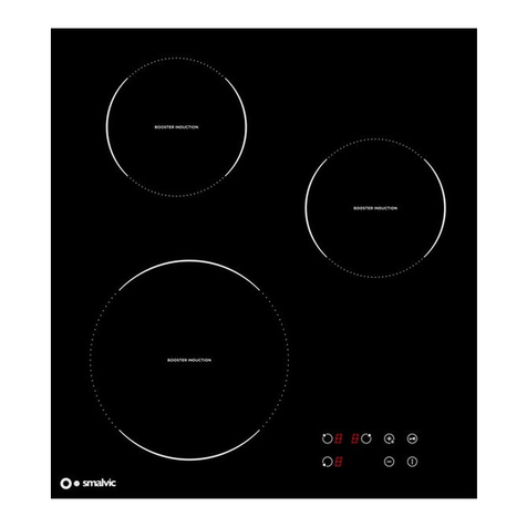
Smalvic 1023850400 User manual
Smalvic
Smalvic PVC Installation and operating instructions
Smalvic
Smalvic PI-EL SERIES Troubleshooting guide
Smalvic
Smalvic PI-Z60V3G1TC User manual

