smart acoustic SM6 User manual
USER MANUAL
SM6
SM8
Multi-purpose Portable PA
FOR YOUR OWN SAFETY , PLEASE READ THIS USER
MANUAL CAREFULLY BEFORE YOUR INITIAL USE.
In order to maintain product condition and to ensure safe operation, it is absolutely
necessary for the user to follow the safety instructions and warning notes contained
in this manual.
CAUTION!
Pay attention when operating this product. If used incorrectly,
or other than intended, you may suff er electrical shock.
CAUTION!
Keep this device away from rain and moisture.
CAUTION!
This speaker system must never be suspended, or stacked.
Only to be used on a stable surface or speaker stand.
WARNING!
This speaker system must only be operated with reasonable
caution in order to avoid hearing loss due to excessive
sound pressure levels. The diff erent local conditions must be
considered in terms of safety.
2

(
typic
Damages caused by the disregard of this User Manual are not subjectto warranty. The Dealer will notaccept
liability for any resulting defects or problems.
Unpacking
Please make sure that there are no obvious transport damages.
Should you notice any damages on the connection panelor on the
casing, do not use the speaker system and immediately consult your
local dealer.
Protection Class
This device falls under protection class I. The power plug must only
be plugged into a protection class I outlet. The voltage and
frequency must be exactly the same as stated on the device.
Wrong voltages or power outlets can lead to the damage of the
device and to electrical shock.
Power Chord
Always plug in the power plug last. The power plug must always be
inserted without force. Make sure that the plug is tightly connected
with the outlet. Never let the power chord come into contact with
other cables! Handle the power chord and all connections with the
m
ai
n
s w
i
th partic
u
lar ca
u
tio
n. Neve
r touch th
em
w
i
th wet hands, as
this could lead to electrical shock. Never modify, bend, strain
mechanically, putpressure on, pull or heatup the power chord.
Never operate next to sources of heator cold. Disregard can lead
to power chord damages, fire or electrical shock. The cable insert
or the female part of the device must never be strained. There
must always be sufficient cable to the device. Otherwise, the cable
may be damaged which may lead to electrical shock. Make sure
that the power chord is never crimped or damaged by sharp edges.
Check the device and the power chord from time to time. If extension
chordsare used, make sure thatthe core diameter is sufficientfor
the required power consumption of the device. All warnings
concerning the power chordsare also valid for possible extension
chords. Always disconnect from the mains, when the device is not in
use or before cleaning it. Only handle the power chord by the plug.
Never pull out the plug by tugging the power chord. Otherwise, the
cable or plug can be damaged leading to electrical shock. If the
power plug or the power switch is not accessible, the device must be
disconnected via the mains.
If the power plug or the device is dusty, the device must be taken
out of operation, disconnected and then be cleaned with a dry cloth.
Dust can reduce the insulation which may lead to mortal electrical
shock.
Liquids
There must never enter anyliquid into power outlets, extension
chords or anyholes in the housing of the device. If you suppose that
also a minimal amount of liquid may have entered the device, it
must immediately be disconnected. This is also valid if the device
was exposed to high humidity. If the device is stillrunning, it must be
checked by a specialist if the liquid had reduced any insulation.
Reduced insulation may cause electric shock.
Foreign Objects
There must never be anyobjects entering into the device. This is
especially valid for metal parts. If any metal parts like staples enter
into the device, the device must be taken out of operation and
disconnected immediately. Malfunction or short- circuits caused by
metal parts may cause mortal injuries.
Secure Setup
Please note that speaker systems may shift due to bass beats and
vibrations. Unintended pushes from performers or the audience
present further risk. This is why the speaker system must always be
secured or the respective area has to be blocked.
Prior to Switching on
Before the speaker system is switched on, all volume controls have
to be set to zero or minimum position.
Maintenance and Service
There are no serviceable parts inside the speaker system.
Maintenance and service operations are only to be carried out by
authorized dealers.
Power Supply
This product is allowed to be operated with an alternating current of
100-240 V, 50/60 Hz and was designed for indoor use only. The
occupation of the connection cables is as follows:
The earth has to be connected. If the device is directly connected with
the local power supply network, a disconnection switch with a minimum
opening of 3 mm at everypole has to be included in the permanent
electrical installation. The device must only be connected with an
electric installation carried out in compliance with the IEC standards.
The electric installation must be equipped with a Residual Current
Device (RCD) with a maximum fault current of 30 mA.
Public and Industrial Use
Operating an amplification system in publicor industrial areas, a series
of safety instructions must be followed that this manual can only give in
part. The operator must therefore inform himself on the current safety
instructions and consider them.
Maximum Power
The maximum power of the speaker system must never be exceeded.
When operating the speaker system, please ensure that the loudspeakers
always sound ok. When distortions can be heard, either the amplifier
or loudspeaker is overloaded. Overloads can rapidly lead to equipment
damage. In order to avoid damage, please reduce the volume
immediately when distortions can be heard. If speaker system is
damaged by overload, the guarantee is void.
Admissible Temperatures
The ambient temperature must always be between -5° C and +45 ° C.
Keep away from direct insulation (particularly in cars) and heaters.
Operation
Operate the speaker system only after having familiarized with its
functions. Do not permit operation by persons not qualified. Most
damages are the result of unprofessionaloperation.
Cleaning
Never use solvents or aggressive detergents in order to clean the
device. Only use a soft and damp cloth.
Modifications and Guarantee
Please consider that unauthorized modificationson the speaker system
are not recommended due to safety reasons. If the speaker system is
operated in a way different to the one described in this manual, the
product may suffer damagesand the guarantee willbecome void.
Furthermore,incorrect operation may lead to dangers like hearing
loss etc.
3

6 5 4 3 2 1
7
8
912
10 13
11
15 14
Controls and Functions
4

1. VOLUME CONTROL – Adjust the volume of your microphone, instrument or audio source.
2. HIGH CONTROL – Adjust the high-frequency balance of your microphone, instrument or audio source.
3. LOW CONTROL – Adjust the low-frequency balance of your microphone, instrument or audio source.
4. REVERB CONTROL – Adjust the amount of reverb applied to your microphone or instrument.
5. LINE/MIC SWITCH – Switch to the LINE or MIC position to apply correct gain for input signal impedance.
6. SIGNAL INPUT – Analog input for connecting microphone (XLR) and instrument (1/4 inch, 6.3mm Jack) cables.
7. SIGNAL INPUT-Analog input for connecting RCA and AUX 3.5mm Jack cables.
8. BLUETOOTH PAIR BUTTON – Used to set up pairing with Bluetooth-capable devices, such as mobile phones,
tablets, and laptops (see “Bluetooth Pairing”).
9. MIX OUT -This is a male XLR-type connector that produces a processed mix of both Mic/Line Inputs. Use it to
daisy-chain several active speakers together or send mix signal to a mixing desk, recording input etc.
10. USB 5V 2A CHARGER - to charge a phone, tablet or USB device. No USB Audio Playback.
11. USAGE POSITION SWITCH - used to enable diff erent Global EQ settings to provide optimal output clarity,
depending on usage position e.g. Upright, Fold Back or Tilt Back.
12. MASTER VOLUME - This controls the overall level of the speaker.
13. BATTERY STATUS - When you connect the power cable, you can check battery charge (even without switching
the unit on) basing on how many of the four LEDs are on. When charge level is below 25%, the red LED fl ashes
and indicates that you need to re-charge the battery as soon as possible.
14. POWER SWITCH - Switch up to turn the speaker on, and switch down to turn it off . Make sure the level control is
down before you turn it on.
15. IEC SOCKET WITH FUSE HOLDER - Plug the power cord into an AC socket properly confi gured for your
particular model. In case of fuse burn, to prevent the risk of fi re and damaging the unit, please use only of the
recommended fuse type as described in Specifi cations. Before replacing the fuse, make sure the unit turned off
and disconnected from the AC outlet.
6 5 4 3 2 1
7
8
912
10 13
11
15 14
Controls and Functions
5
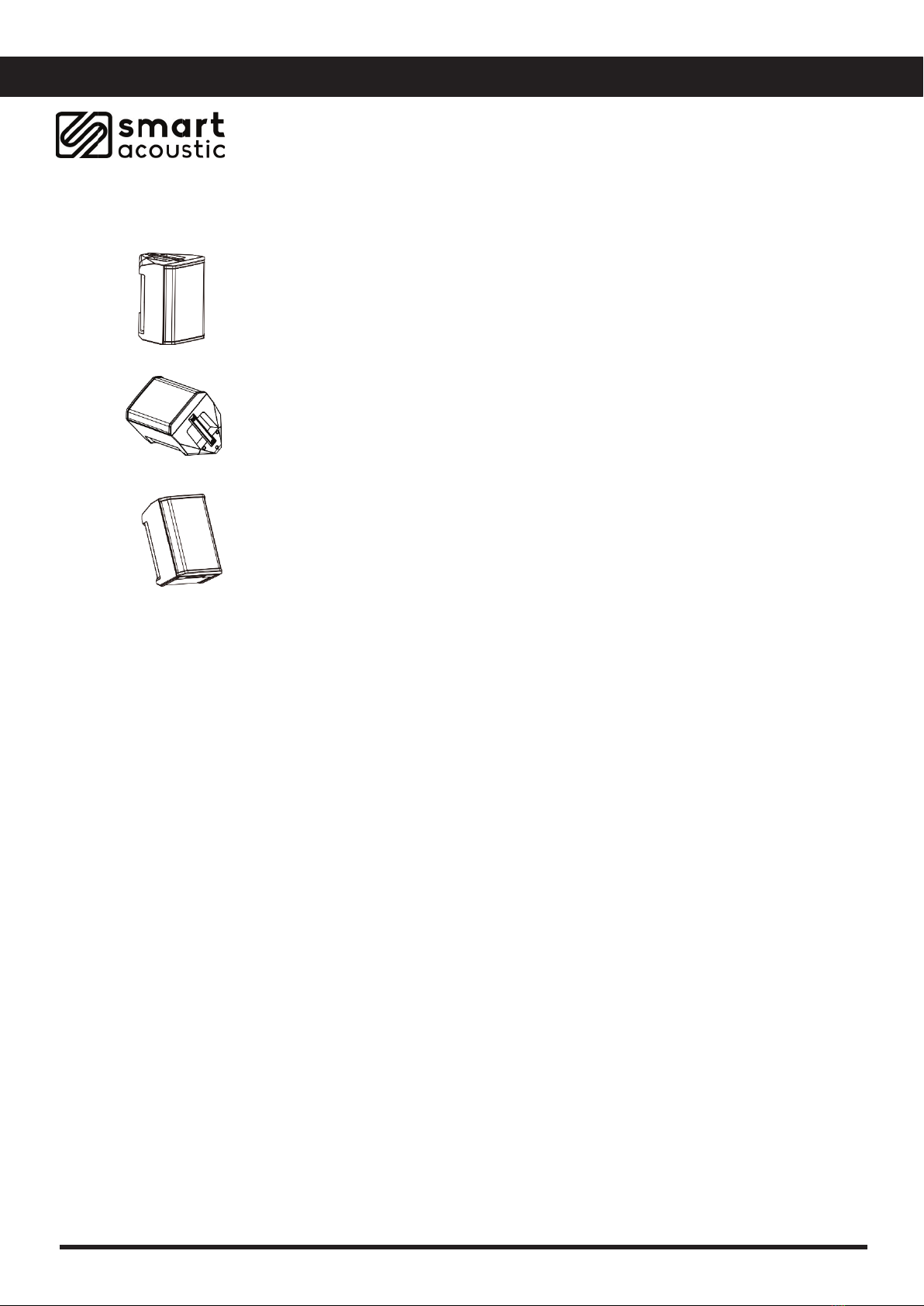
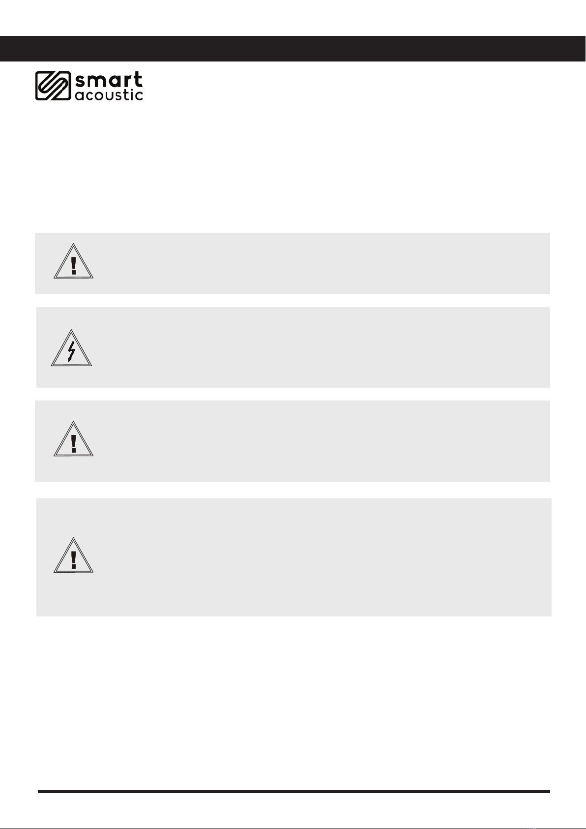
Upright / Elevated Surface
Position speaker on a stable surface or 35mm speaker stand. This projects sound
clearly and evenly throughout the audience, and ensures that audience members
enjoy the full frequency range of the system.
Fold Back Monitor
To use the speaker as a personal fl oor monitor, place it on the ground
horizontally, in front of and pointing toward the performer. Tilt the loudspeaker onto its
side edge.
Tilt-Back
For performances where your audience is close to you, tilt the speaker onto its back
edge. For best results, the performer should stand or sit to one side of the loudspeaker
to avoid blocking sound from the audience.
Position Scenarios
6
Bluetooth Pairing Function
- Turn your SM’S power switch to the ON position.
- Bluetooth Pairing mode will automatically engage, shown by fast fl ashing Blue LED.
- On your phone, tablet or Bluetooth enabled device select ‘Smart SM6’ or ‘Smart SM8’, from your
Bluetooth devices menu.
- SM unit will announce ‘Bluetooth Connected’ and blue LED will light Solid Blue.
- When Bluetooth audio is streamed from your device, the blue LED will fl ash slow and steady.
- To disconnect Bluetooth simply press and hold the ‘PAIR’ button or disconnect from your Bluetooth
devices menu on your streaming device.
Or simply switch the SM unit power button to OFF.

M
odel: SM6
Product type:
Multi-purpose Portable PA Speaker
Type:
Active
Low/mid driver dimensions :
6.5"
Woofer magnet:
Ferrite
Vertical array system:
3x2.75"Wideband Speakers
Amplifier:
2 x Class D
RMS:
100W+100W
Peak power:
200W+200W
Frequency response:
65Hz-20kHz
SPL(1W/1m):
93dB
Max.SPL:
110dB
Protection circuits:
Short circuit overcurrent
Controls:
Master, Volume, Treble (High), Bass (Low), Reverb, Line/Mic Switch
Indicators:
Charge, Battery, status, Power, Limit
Audio Inputs:
2 x XLR/6.3mm Jack combo / RCA / 3.5mm/ Bluetooth
Line inputs:
3
Mix outputs:
1
Line output connectors:
XLR
Operating Voltage:
Fuse Type
AC 100-240V 50/60Hz
T2A/250V
Battery capacity
6 hours 100% power / 10 hours 50% power // 28.8V /5,200mAh (typical usage)
Cabinet material:
Polypropylene
Cabinet construction:
Vented
Other features:
35mm stand mount, transport handle
Dimensions(WxHxD):
365 x 480 x 320mm
Weight:
8.12kg
M
odel: SM8
Product type:
Multi -purpose Portable PA Speaker
T
ype: Active
L
ow/mid driver dimensions : 8"
W
oofer magnet: Ferrite
V
ertical array system: 3x2.75"Wideband Speakers
A
mplifier: 2xClass D
R
MS:120W+120W
P
eak power: 240W+240W
F
requency response: 50Hz-20kHz
S
PL(1W/1m): 95dB
M
ax.SPL: 120dB
P
rotection circuits: Short circuit overcurrent
C
ontrols: Master, Volume, Treble (High), Bass (Low), Reverb, Line/Mic Switch
I
ndicators: Charge, Battery Status/Power, Limit
A
udio Inputs: 2 x XLR/6.3mm Jack combo / RCA / 3.5mm/ Bluetooth
L
ine inputs: 3
M
ix outputs: 1
L
ine output connectors: XLR
O
perating Voltage: AC 100-240V 50/60Hz
B
attery capactity:
6hours 100% power /10
hours 50% power // 28.8V /5,200mAh
(typical usage)
C
abinet material: Polypropylene
Cabinet construction:
vented
O
ther features: 35mm stand mount, transporthandle
D
imensions(WxHxD): 410 x 515 x 362mm
W
eight: 9.46kg
Fuse Type
T2A/250V
7

This manual suits for next models
1
Table of contents


