Smart-Fly PowerExpander Eq10 User manual

Receive Power LED Indicators
The receiver power LEDs indicate the receiver is getting power. It
does not actually recognize if the receiver is getting the 5V it should
get.
Optional Failsafe-switch
Warning: Always ake sure the failsafe-switch is off
before charging through the PowerExpanerEq. Failure
to do so ay result in the servos getting a voltage too
high for the resulting in servo failure.
The failsafe-switch and charge jacks can only be used
when batteries are plugged directly into the
PowerExpander.
The PowerExpander E 10 supports the addition of a failsafe switch
(optional package) for use when batteries are being used without
regulators. The PowerExpander E 10 supports 5-cell NiCd or NiMH
or 2-cell lithium packs, ion or poly. When using the failsafe-switch, the
switch lead is plugged into the input marked “Sw” near the bottom
right of the servo connections as shown on the reference drawing.
Smart-Fly provides two types of failsafe switches. First is the standard
slide switch that most people are familiar with. This is a small slide
switch with out a charge jack. The second failsafe-switch is the
Pin&Flag switch, where a pin, with a flag on in, is inserted into the
switch to turn the system off. To fly, the pin is pulled out of the switch.
The advantage of the Pin&Flag switch is that the system cannot
accidentally be turned off, as can be the case with a slide switch. The
failsafe switch lead can be extended using a standard Futaba extension.
The PowerExpander E 10 also supports charging the batteries through
the two “Chg” connections, one on the bottom of each servo output rail
as shown on the reference drawing. The optional failsafe-switch
package includes two charge leads and two Ernst charge jack mounts.
The charge leads have a Futaba male on one end and a JR male on the
other end. You may use these by plugging either end into the
PowerExpander E 10 and the other end into the charge jack holder.
The charge jacks on the PowerExpander E 10 can also be used to
connect to a battery meter. One thing to keep in mind when using a
battery meter and the failsafe-switch is that the jacks are not switched
off when the unit is off so the battery meter will continue to draw
power when the unit is turned off.
Typical Installation Configurations
Additional information and technical help can be found at
www.Smart-Fly.com
Quest Engineering & Development, Inc.
6125 South Ash Avenue, STE B-8
Tempe, AZ 85283
Ph: (480) 460-2652 Fax: (480) 460-2653
P
PP
P
P
PP
Po
oo
o
o
oo
ow
ww
w
w
ww
we
ee
e
e
ee
er
rr
r
r
rr
rE
EE
E
E
EE
Ex
xx
x
x
xx
xp
pp
p
p
pp
pa
aa
a
a
aa
an
nn
n
n
nn
nd
dd
d
d
dd
de
ee
e
e
ee
er
rr
r
r
rr
r
E
EE
E
E
EE
Eq
qq
q
q
qq
q1
11
1
1
11
10
00
0
0
00
0
User Guide
Thank you for purchasing the
Smart-Fly PowerExpander Eq10
This manual takes you through the installation and operation of
the Smart-Fly PowerExpander E 10 unit. The unit is a power
distribution unit that supplies full power to your servos while
supplying a clean, regulated voltage to your receiver. Features
of the PowerExpander E 10 are:
Light weight, 2.6oz, 74g
Co pact design, footprint is 4-1/2” x 3”
Input Voltage range of 5.5V-8.5V
End-loading and top-loading receivers supported
Filtered and regulated 5.0V power to the receiver
1-a p receiver regulator
“S art-Sense” inputs for error detection
Long servo lead line atching
LED power indicators for input and receiver power
Fully buffered outputs on all channels
Full RF filtering of all signals in and out of the unit
High-current Deans UltraPlug power input
connectors
Optional failsafe-switch and charge jack package
available
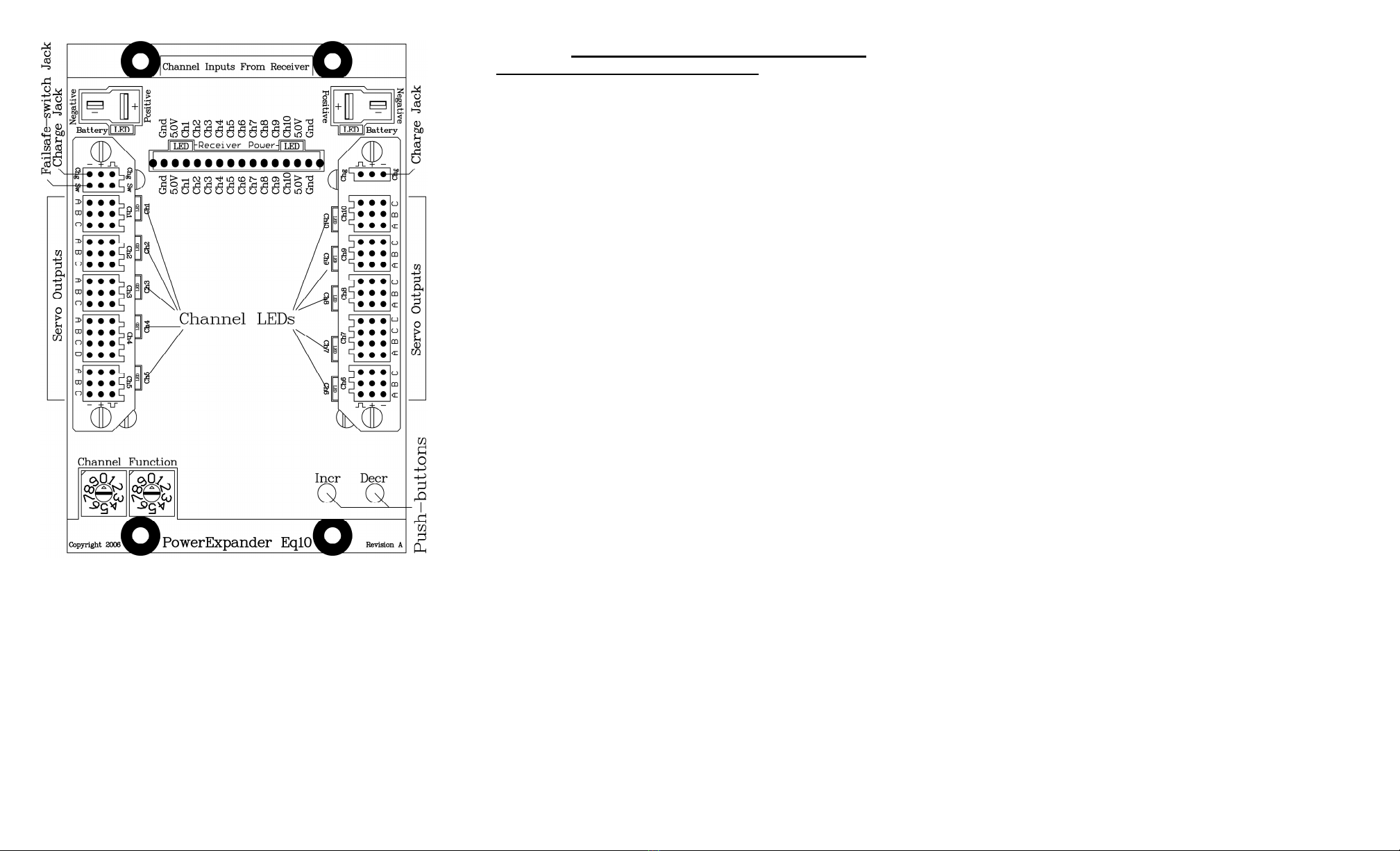
Reference Drawing
Receiver Mounting
The receiver mounts in the center of the unit. 3M dual-lock mounting
tape has been supplied to mount the receiver. This tape’s holding power
is extremely strong so it is recommended that the whole 1”x2” piece not
be used. Instead it is recommended that you cut some 1”x ½” strips and
use these on either end of the receiver.
Receiver Connections
CAUTION: Do not plug any receiver pigtails into the battery
input of your receiver. On PCM it will put your receiver into
DSC ode, on a 2.4GHz receivers it ay cause your receiver
to unbind. All connections fro the PowerExpander are
eant to ONLY plug into servo outputs.
The receiver servo outputs are connected to the pigtails coming out of
the PowerExpander E 10 in the area marked “Channel Inputs From
Receiver” on the reference drawing. The two channels on the end
(“Chan 1” and “Chan 10”) have power connections to the receiver in
addition to the signal connection. It is recommended that if you have a
receiver that has less than ten channels that you still use both the end
connections as this will provide you with power redundancy to the
receiver in event that a power or ground lead should fail.
The unit will accommodate both end-loading receivers and top-loading
receivers. All signals coming from the receiver into the PowerExpander
E 10 are RF filtered. This prevents noise from the servos from going
out the receiver connectors into the receiver. If not all channels are
going to be used then the unused pigtail can be tucked away.
Connections Directly To Receiver
If you want to connect a device directly to the receiver instead of going
through the PowerExpander E 10, make sure the current draw of the
receiver and the device is less than one amp.
We do not recommend plugging any servos directly into the receiver.
They can draw too much current, even analog servos. Devices that may
be plugged directly into the receiver are the Smart-Fly Ignition Cutoff
and some smoke pumps.
Servo Connections
Servos are connected to the PowerExpander E 10 along the two rails on
either side of the receiver. The servo connectors are universal in that
they will work with Futaba or JR connectors. When using a JR
connector please be careful to observe the polarity of the connection.
The negative servo power lead (black on Futaba, brown on JR) is
indicated by the “minus” sign. The positive servo power lead (red on
Futaba and JR) is indicated by the “plus” sign. The servo signal line
(white on Futaba, orange on JR) is indicated by the “top hat” symbol.
All receiver channels have each servo signal output individually
buffered. If a servo were to short out its signal wire, the other servos on
that channel would not be affected. Eight of the channels have three
servo outputs and two of the channels have four servo outputs. The
channels with four servo outputs correspond to Futaba and JR’s
assignments of the rudder channel.
The unit also RF filters each signal output and matches line impedance
resulting in a cleaner signal down long servo leads. The impedance
matching reduces the electrical “ringing” that can occur on long servo
leads. Ringing can generate RF interference and can reduce receiver
range.
“S art-Sense” Power Connections
Power is connected to the unit through the two Deans UltraPlug male
connectors. The polarity of the Deans connector is shown on the
reference drawing. The “Smart-Sense” power inputs will show, by the
LED for that input being lit, that the input connector is enabled. When
an input is enabled, the voltage drop into the unit is less than 0.15V at
five amps and less than 0.3V at ten amps. This is much less than a diode
voltage drop, which most other units use. The Smart-Sense” input
recognizes this by the fact the two input sources are within 20 millivolts
of each other. When the LED for an input is not lit that input is turned
off and power cannot flow out of the connector, as would be the case if a
pack shorted.
If one LED is not lit then the power on that connector may have
something wrong with it. This could be one of several things. If you
have batteries connected directly to the unit then the two packs may not
be charged to the same level. The higher pack will be drawn from until
the two packs e ualize in voltage. After the pack voltages e ualize
power will be drawn from both batteries. If one pack has lost a cell and
is at a much lower voltage this e ualization will never happen and the
power to the system will come from the good pack. If a pack should
short, that input will be disabled and the system will run off the good
pack.
If regulators are being used on the two inputs then one regulator may be
set more than 20 millivolts below the regulator that has the LED lit or
the regulator may have gone bad. The “Smart-Sense” inputs can be used
to get dual regulators in the “neighborhood” of being e ual but it should
be remembered that regulators will not draw evenly when their outputs
are connected together, unless they are matched to less than a hundredth
of a volt which is very hard to do and may be impossible for a given set
of regulators. One thing to remember if you are using adjustable
regulators and one battery pack is going down faster than the other,
adjust the voltage up of the regulator on the battery pack that is being
used less.
It is highly recommended that you beef up the power wiring between
the battery and the PowerExpander E 10 above the standard 22ga
wiring. Failure to do this will diminish the effectiveness of the
PowerExpander E 10 at providing the highest possible voltage to the
servos. Servos operating at lower voltages produce less tor ue than they
are rated.


