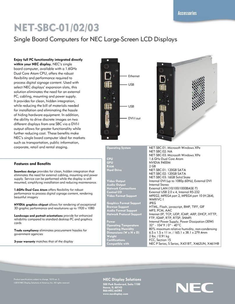
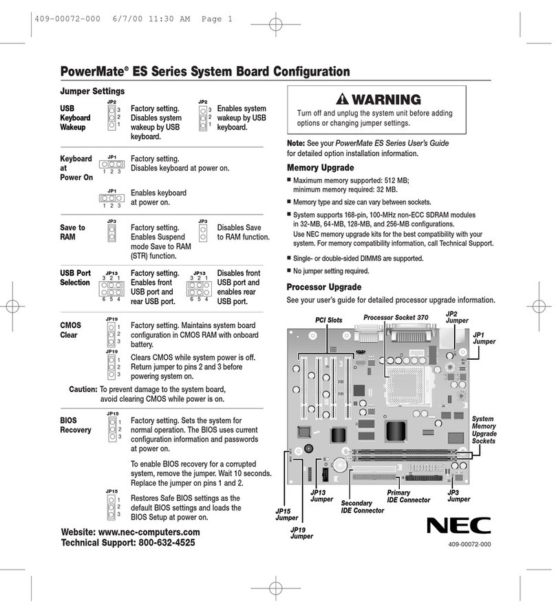
NEC PG-FPL2 User manual

Document No. U17307EJ2V0UM00 (2nd edition)
Date Published December 2004 NS CP(K)
Printed in Japan
2004
User’s Manual
PG-FPL2
Flash Memory Programmer

User’s Manual U17307EJ2V0UM
2
[MEMO]

User’s Manual U17307EJ2V0UM 3
Windows and Windows NT are either registered trademarks or trademarks of Microsoft Corporation in the
United States and/or other countries.
PC/AT is a trademark of International Business Machines Corporation.
Pentium is a trademark of Intel Corporation.
The information in this document is current as of December, 2004. The information is subject to
change without notice. For actual design-in, refer to the latest publications of NEC Electronics data
sheets or data books, etc., for the most up-to-date specifications of NEC Electronics products. Not
all products and/or types are available in every country. Please check with an NEC Electronics sales
representative for availability and additional information.
No part of this document may be copied or reproduced in any form or by any means without the prior
written consent of NEC Electronics. NEC Electronics assumes no responsibility for any errors that may
appear in this document.
NEC Electronics does not assume any liability for infringement of patents, copyrights or other intellectual
property rights of third parties by or arising from the use of NEC Electronics products listed in this document
or any other liability arising from the use of such products. No license, express, implied or otherwise, is
granted under any patents, copyrights or other intellectual property rights of NEC Electronics or others.
Descriptions of circuits, software and other related information in this document are provided for illustrative
purposes in semiconductor product operation and application examples. The incorporation of these
circuits, software and information in the design of a customer's equipment shall be done under the full
responsibility of the customer. NEC Electronics assumes no responsibility for any losses incurred by
customers or third parties arising from the use of these circuits, software and information.
While NEC Electronics endeavors to enhance the quality, reliability and safety of NEC Electronics products,
customers agree and acknowledge that the possibility of defects thereof cannot be eliminated entirely. To
minimize risks of damage to property or injury (including death) to persons arising from defects in NEC
Electronics products, customers must incorporate sufficient safety measures in their design, such as
redundancy, fire-containment and anti-failure features.
NEC Electronics products are classified into the following three quality grades: "Standard", "Special" and
"Specific".
The "Specific" quality grade applies only to NEC Electronics products developed based on a customer-
designated "quality assurance program" for a specific application. The recommended applications of an NEC
Electronics product depend on its quality grade, as indicated below. Customers must check the quality grade of
each NEC Electronics product before using it in a particular application.
The quality grade of NEC Electronics products is "Standard" unless otherwise expressly specified in NEC
Electronics data sheets or data books, etc. If customers wish to use NEC Electronics products in applications
not intended by NEC Electronics, they must contact an NEC Electronics sales representative in advance to
determine NEC Electronics' willingness to support a given application.
(Note)
•
•
•
•
•
•
M8E 02. 11-1
(1)
(2)
"NEC Electronics" as used in this statement means NEC Electronics Corporation and also includes its
majority-owned subsidiaries.
"NEC Electronics products" means any product developed or manufactured by or for NEC Electronics (as
defined above).
Computers, office equipment, communications equipment, test and measurement equipment, audio
and visual equipment, home electronic appliances, machine tools, personal electronic equipment
and industrial robots.
Transportation equipment (automobiles, trains, ships, etc.), traffic control systems, anti-disaster
systems, anti-crime systems, safety equipment and medical equipment (not specifically designed
for life support).
Aircraft, aerospace equipment, submersible repeaters, nuclear reactor control systems, life
support systems and medical equipment for life support, etc.
"Standard":
"Special":
"Specific":
User’s Manual U17307EJ2V0UM
4
GENERAL PRECAUTIONS FOR HANDLING THIS PRODUCT
1. Circumstances not covered by product guarantee
•If the product was disassembled, altered, or repaired by the customer
•If it was dropped, broken, or given another strong shock
•Use at over voltage, use outside guaranteed temperature range, storing outside guaranteed
temperature range
•If power was turned on while the USB cable or target system connection was in an unsatisfactory
state
•If the USB cable, target cable, or the like was bent or pulled excessively
•If the product got wet
•If the product and target system were connected while a potential difference existed between the
GND of the product and the GND of the target system
•If a connector or cable was removed while the power was being supplied to the product
•If an excessive load was placed on a connector or socket
2. Safety precautions
•If used for a long time, the product may become hot (50°C to 60°C). Be careful of low temperature
burns and other dangers due to the product becoming hot.
•Be careful of electrical shock. There is a danger of electrical shock if the product is used as
described above in 1Circumstances not covered by product guarantee.

User’s Manual U17307EJ2V0UM 5
Regional Information
• Device availability
• Ordering information
• Product release schedule
• Availability of related technical literature
• Development environment specifications (for example, specifications for third-party tools and
components, host computers, power plugs, AC supply voltages, and so forth)
• Network requirements
In addition, trademarks, registered trademarks, export restrictions, and other legal issues may also vary
from country to country.
[GLOBAL SUPPORT]
http://www.necel.com/en/support/support.html
NEC Electronics America, Inc. (U.S.)
Santa Clara, California
Tel: 408-588-6000
800-366-9782
NEC Electronics Hong Kong Ltd.
Hong Kong
Tel: 2886-9318
NEC Electronics Hong Kong Ltd.
Seoul Branch
Seoul, Korea
Tel: 02-558-3737
NEC Electronics Shanghai Ltd.
Shanghai, P.R. China
Tel: 021-5888-5400
NEC Electronics Taiwan Ltd.
Taipei, Taiwan
Tel: 02-2719-2377
NEC Electronics Singapore Pte. Ltd.
Novena Square, Singapore
Tel: 6253-8311
J04.1
N
EC Electronics (Europe) GmbH
Duesseldorf, Germany
Tel: 0211-65030
•Sucursal en España
Madrid, Spain
Tel: 091-504 27 87
Vélizy-Villacoublay, France
Tel: 01-30-67 58 00
•Succursale Française
•Filiale Italiana
Milano, Italy
Tel: 02-66 75 41
•Branch The Netherlands
Eindhoven, The Netherlands
Tel: 040-244 58 45
•Tyskland Filial
Taeby, Sweden
Tel: 08-63 80 820
•United Kingdom Branch
Milton Keynes, UK
Tel: 01908-691-133
Some information contained in this document may vary from country to country. Before using any NEC
Electronics product in your application, pIease contact the NEC Electronics office in your country to
obtain a list of authorized representatives and distributors. They will verify:

User’s Manual U17307EJ2V0UM
6
PREFACE
Target Readers This manual is intended for users who use the PG-FPL2 when designing and
developing a system using an NEC Electronics on-chip flash memory
microcontroller.
Purpose This manual is intended to give users an understanding of the basic specifications
and correct use of the PG-FPL2.
By using the PG-FPL2, programs can be easily erased from or written to the flash
memory of an NEC Electronics 78K0S/Kx1+ Series on-chip flash memory
microcontroller, or can be verified on WindowsTM screens, while the microcontroller is
mounted on the user board.
Organization This manual includes the following sections.
•Overview
•Hardware installation
•Software installation
•Operation using GUI software
•Usage examples
•Connectors and cables
•Notes on target system
•Circuit diagrams
•Troubleshooting
How to Read This Manual To understand the overall functions and usage of the PG-FPL2, read this manual in
the order of the CONTENTS.
Be sure to read CHAPTER 4 OPERATION USING GUI SOFTWARE because this
chapter presents important information for using the PG-FPL2.
It is assumed that the readers of this manual have general knowledge of electricity,
logic circuits, and microcontrollers.
In the explanations of the operation of the applications, it is also assumed that the
readers have sufficient knowledge of Windows.
For the usage and terminology of Windows 98, Windows Me, Windows 2000, and
Windows XP, refer to each Windows manual.
The mark shows major revised points.

User’s Manual U17307EJ2V0UM 7
Conventions Note: Footnote for item marked with Note in the text.
Caution: Information requiring particular attention
Remark: Supplementary information
Numeral representation: Binary … ×××× or ××××B
Decimal … ××××
Hexadecimal … 0××××H or ××××H
“ ”: Any character or item on screen
OK : Name of button
[ ]: Menu
< >: Dialog box name
Terminology The meanings of the terms used in this manual are as follows.
Term Meaning
FPL2 Abbreviation of flash memory programmer PG-FPL2
GUI software Windows application to operate PG-FPL2 using GUI software
Target device NEC Electronics on-chip flash memory microcontroller
Target system User-designed board on which NEC Electronics on-chip flash
memory microcontroller is mounted
FP4 connector Abbreviation of PG-FP4 target connector (type A)
FA adapter Adapter board to write programs to NEC Electronics on-chip flash
memory microcontrollerNote
78K0S/Kx1+ Generic name of 78K0S/KU1+, 78K0S/KY1+, 78K0S/KA1+, and
78K0S/KB1+
Note The FA adapter board is a product of Naito Densei Machida Mfg. Co., Ltd.
If you have any questions about the FA adapter board, contact:
Naito Densei Machida Mfg. Co., Ltd. Tel: +81-45-475-4191

User’s Manual U17307EJ2V0UM
8
CONTENTS
CHAPTER 1 OVERVIEW......................................................................................................................... 10
1.1 Features .................................................................................................................................... 10
CHAPTER 2 HARDWARE INSTALLATION .......................................................................................... 11
2.1 System Requirements .............................................................................................................11
2.2 Package Contents .................................................................................................................... 11
2.3 System Configuration and Components ............................................................................... 12
2.3.1 FPL2 display specifications, connector, and MODE switch settings ...............................................12
2.3.2 FPL2-FA connector.........................................................................................................................13
2.3.3 Target system .................................................................................................................................13
2.3.4 USB connector................................................................................................................................13
2.3.5 Target cable....................................................................................................................................13
2.3.6 Connection procedure.....................................................................................................................14
2.3.7 Disconnection procedure ................................................................................................................16
CHAPTER 3 SOFTWARE INSTALLATION ........................................................................................... 17
3.1 GUI Software Installation......................................................................................................... 17
3.2 USB Driver Installation ............................................................................................................ 23
3.2.1 Installation in Windows 98/Me ........................................................................................................23
3.2.2 Installation in Windows 2000 ..........................................................................................................26
3.2.3 Installation in Windows XP..............................................................................................................29
3.3 Confirmation of USB Driver Installation ................................................................................ 31
3.4 Uninstallation............................................................................................................................ 32
3.4.1 Driver uninstallation ........................................................................................................................32
3.4.2 GUI software uninstallation .............................................................................................................32
CHAPTER 4 OPERATION USING GUI SOFTWARE .......................................................................... 35
4.1 Introduction .............................................................................................................................. 35
4.2 Starting up GUI Software......................................................................................................... 35
4.3 Toolbar ...................................................................................................................................... 36
4.4 Menus ........................................................................................................................................ 36
4.4.1 [File] menu ......................................................................................................................................36
4.4.2 [Device] menu.................................................................................................................................38
4.4.3 [View] menu ....................................................................................................................................46
4.4.4 [Help] menu ....................................................................................................................................47
4.5 Programmer Parameter Window ............................................................................................ 48
CHAPTER 5 USAGE EXAMPLE ............................................................................................................ 49
CHAPTER 6 CONNECTORS AND CABLES........................................................................................ 55
6.1 USB Connector (FPL2) ............................................................................................................55
6.2 Target Cable Connector (FPL2) .............................................................................................. 56

User’s Manual U17307EJ2V0UM 9
6.3 Target Cable Specifications.....................................................................................................57
6.4 Target Connector (FPL2-FA)....................................................................................................57
6.5 FP4 Connector (FPL2-FA) ........................................................................................................58
6.6 List of Interface Connections ..................................................................................................59
CHAPTER 7 NOTES ON TARGET SYSTEMS.....................................................................................60
CHAPTER 8 CIRCUIT DIAGRAMS.........................................................................................................63
CHAPTER 9 TROUBLESHOOTING ........................................................................................................65
9.1 Trouble During Setup ...............................................................................................................65
9.2 Trouble During Operation (Main Unit) ....................................................................................66
9.3 Trouble During Operation (Communication) .........................................................................66
APPENDIX A PRODUCT SPECIFICATIONS .........................................................................................68
A.1 Hardware Specifications ..........................................................................................................68
A.2 Dimensions................................................................................................................................69
APPENDIX B WARRANTY AND SUPPORT...........................................................................................72
B.1 Warranty ....................................................................................................................................72
B.2 Support ......................................................................................................................................72
APPENDIX C REVISION HISTORY ........................................................................................................73

User’s Manual U17307EJ2V0UM
10
CHAPTER 1 OVERVIEW
The PG-FPL2 is a tool that erases and writes programs on an NEC Electronics 78K0S/Kx1+ Series on-chip flash
memory single-chip microcontroller on the target board or FA adapter board.
1.1 Features
•The PG-FPL2 is a compact flash memory programmer for an on-chip flash memory microcontroller, and is
designed for development.
•The USB interface is available for connection with the host.
•The PG-FPL2 allows on-board programming without removing the target device from the target system.
•Only single-wire UART interface is supported for data transfer to the target device.
•Device-specific parameters required for programming can be read from the parameter file (PRM file).

User’s Manual U17307EJ2V0UM 11
CHAPTER 2 HARDWARE INSTALLATION
2.1 System Requirements
Host PC A PC supporting Windows 98, Windows Me, Windows 2000, or Windows XP is required to run
the FPL2 in the graphical user interface (GUI) mode.
About 2 MB of free hard disk space is required to install the GUI software.
Host machine IBM PC/ATTM or compatible
CPU: PentiumTM 100 MHz or more
RAM: 32 MB or more
Host interface USB interface that enables communication based on USB (Ver. 1.1 or later).
File formats Program files can be used in Motorola HEX file format or Intel HEX file format.
2.2 Package Contents
Please verify that you have received all the parts listed in the package contents list included with the FPL2
package. If any part is missing or seems to be damaged, please contact an NEC Electronics sales representative or
distributor.

CHAPTER 2 HARDWARE INSTALLATION
User’s Manual U17307EJ2V0UM
12
2.3 System Configuration and Components
The FPL2 system configuration is as given in the diagram below.
Figure 2-1. FPL2 System Configuration
USB cable
(Mini-B type)Note 1
Target system
compatible with FP4
connector
Host machine
Target cable FPL2-FA
PG-FPL2
FA adapterNote 2
ID78K0S-QB Disk
Target system not
compatible with FP4
connector
Notes 1. Use the USB cable (Mini-B type) included with the QB-78K0SKX1MINI.
2. The FA adapter board is a product of Naito Densei Machida Mfg. Co., Ltd.
The FPL2 is connected to the host machine via the USB cable (Mini-B type). The FPL2 is connected to the user
system via the target cable. For the detailed specifications of the target cable and connector, refer to CHAPTER 6
CONNECTORS AND CABLES.
2.3.1 FPL2 display specifications, connector, and MODE switch settings
Figure 2-2. Layout Drawing of Connectors and LEDs
MODE switch
Target cable connector
USB connector
Power LED Status LED

CHAPTER 2 HARDWARE INSTALLATION
User’s Manual U17307EJ2V0UM 13
Target cable connector: Used to connect the connector of the target cable.
USB connector: Used to connect the USB cable to be connected to the host machine.
Power LED: Turned on in green when the FPL2 is connected to the host machine.
Status LED: Blinks in red when the FPL2 is communicating with the target device.
MODE switch: Switches power to be supplied to the target system.
Target: Used to supply VDD from the target system.
3 V: Used to supply power to the target system with 3.0 V VDD from
the FPL2.
Caution When the Status LED is blinking, communication with the target device is in progress. Do not
disconnect the target cable and USB cable.
2.3.2 FPL2-FA connector
Figure 2-3. Layout Drawing of FPL2 Connectors
Target connector: Used to connect the tip of the target cable.
FP4 connector: Used to connect the FA adapter board or target system.
2.3.3 Target system
The target system must be equipped with a device interface that complies with the target cable specifications.
Refer to CHAPTER 6 CONNECTORS AND CABLES for details.
2.3.4 USB connector
The shape of the USB connector is a Mini-B type.
Refer to CHAPTER 6 CONNECTORS AND CABLES for details.
2.3.5 Target cable
The tip of the target cable can be connected to the header pin that is 0.635 mm by 0.635 mm.
Refer to CHAPTER 6 CONNECTORS AND CABLES for details.
Target connector
FP4 connector
Component side (front) Soldering side (rear)

CHAPTER 2 HARDWARE INSTALLATION
User’s Manual U17307EJ2V0UM
14
2.3.6 Connection procedure
The procedure for connecting the FPL2 is described below.
Caution Be sure to install the software (GUI software driver) before making connections.
(1) Set the MODE switch according to the power supply of the target system.
Caution Be sure to set the MODE switch before making connections with the host machine and target
system. If connections are made based on an incorrect setting, the FPL2 and target system
may be damaged.
Figure 2-4. MODE Switch Setting
(2) Connect the host machine with the FPL2 via the USB cable. (Check that the Power LED is turned on in green.)
Cautions 1. Be sure to perform this step before making a connection with the target system. If
connections are made in an incorrect order, the FPL2 and target system may be damaged.
2. When the MODE switch is set to 3 V (power is supplied from the FPL2), the voltage output
to the VDD pin when the FPL2 is connected with the host machine.
(3) Connect the target system with the FPL2.
(a) When FPL2 is connected with a target system that has a 16-pin connector usable with the FP4 connector
<1> Connect the tip of the target cable with the target connector of the FPL2-FA.
Connect the tip of the target cable with the target connector of the FPL2-FA so that the number
marked on the tip of the target cable matches to the number marked on the FPL2-FA board.
Remark The FPL2-FA is connected with the target cable at shipment.
Set the MODE switch.

CHAPTER 2 HARDWARE INSTALLATION
User’s Manual U17307EJ2V0UM 15
Figure 2-5. Connecting Target Cable with FPL2-FA
<2> Make sure that the power to the target system is not turned on.
Caution Make sure that the power to the target system is not turned on before connecting
the target cable. If the target cable is connected after the power to the target system
is turned on, the FPL2 may be damaged.
<3> Connect the FP4 connector with the connector installed in the target system.
Caution When the MODE switch is set to 3 V (power is supplied from the FPL2), VDD is always
output from the FP4 connector. Be sure to remove the FP4 connector before
inserting or removing a device in the target system.
<4> Be sure to turn on the power to the target system.
(When the MODE switch is set to 3 V, power is supplied from the FPL2, so this step is not required.)
(b) When the FPL2 is connected with the target system without using the FPL2-FA
<1> Disconnect the FPL2-FA from the target cable.
<2> Make sure that the power to the target system is not turned on.
Caution Make sure that the power to the target system is not turned on before connecting
the target cable. If the target cable is connected after the power to the target system
is turned on, the FPL2 may be damaged.
<3> Connect the tip of the target cable marked "0.GND" to GND of the target system.
Caution Be sure to connect "0.GND" at the beginning. If connections are made in an
incorrect order, the FPL2 and target system may be damaged.
<4> Make sure that the power to the target system is not turned on.
0. GND
Match the number.
Tip of target cable

CHAPTER 2 HARDWARE INSTALLATION
User’s Manual U17307EJ2V0UM
16
<5> Connect the tip of the target cable marked "2.VDD" to VDD of the target system.
Caution Be sure to make connections in the order from "0.GND" to "2.VDD" to "other signals".
If connections are made in an incorrect order, the FPL2 and target system may be
damaged.
<6> Connect the tips of other target cables to the target system.
<7> Turn on the power to the target system.
(When the MODE switch is set to 3 V, power is supplied from the FPL2, so this step is not required.)
2.3.7 Disconnection procedure
(1) When communication with the target system ends, terminate the GUI software.
(2) Disconnect the FPL2-FA from the target system.
(a) When the FPL2 is connected with the target system by using the FPL2-FA
<1> Turn off the power to the target system.
(When the MODE switch is set to 3 V, power is supplied from the FPL2, so this step is not required.)
<2> Disconnect the FPL2-FA from the target system.
Caution When the MODE switch is set to 3 V, the FPL2 outputs power at all times. Be sure to
disconnect the FP4 connector from the target system before disconnecting the
target device.
(b) When the FPL2 is connected with the target system without using the FPL2-FA
<1> Turned off the power to the target system.
(When the MODE switch is set to 3 V, power is supplied from the FPL2, so this step is not required.)
<2> Disconnect the tips of the target cables marked "1./RESET", "3.DGCLK", and "4.DGDATA" from the
target system.
Caution Be sure to disconnect the target cables in this order. If the target cables are
disconnected in an incorrect order, the target system or the FPL2 may be damaged.
<3> Disconnect the tip of the target cable marked "2.VDD" from the target system.
<4> Disconnect the tip of the target cable marked "0.GND" from the target system.
(3) Disconnect the USB cable from the host machine. (Make sure that the Power LED is turned off.)
(4) Disconnect the USB cable from the FPL2.

User’s Manual U17307EJ2V0UM 17
CHAPTER 3 SOFTWARE INSTALLATION
3.1 GUI Software Installation
The GUI software allows easy and comfortable access to all features of the FPL2 flash programmer.
The installation program is contained in the CD-ROM (ID78K0S-QB Disk) included with the QB-78K0SKX1MINI
package.
Execute the following steps to install the GUI software.
(1) When using Windows XP, log on as the computer administrator. When using Windows 2000, log on as the
Administrator.
(2) Insert the CD-ROM (ID78K0S-QB Disk) included with the QB-78K0SKX1MINI package into the CD-ROM drive.
(3) Double-click "My Computer", "CD-ROM", "PG-FPL2", and "SETUP" in that order. Double-click "setup.exe" in
the SETUP folder.
Figure 3-1. SETUP Folder
Double-click

CHAPTER 3 SOFTWARE INSTALLATION
User’s Manual U17307EJ2V0UM
18
(4) Select a language to be used for installation ("English" in this example), then click OK .
Figure 3-2. Setup Language Selection
(5) After selecting the language, the window shown below is displayed.
Click Next > to continue installation.
Figure 3-3. Installation Start
Select language

CHAPTER 3 SOFTWARE INSTALLATION
User’s Manual U17307EJ2V0UM 19
(6) The software License Agreement window appears. Read the displayed license agreement carefully, then click
Yes if you accept the agreement. You need to accept the agreement before using the PG-FPL2. If you do not
accept the agreement, click No to terminate the installation of the software.
Figure 3-4. License Agreement Window
(7) Check that "Typical" is selected, then click Next > .
Figure 3-5. Setup Type
Check that "Typical" is selected.

CHAPTER 3 SOFTWARE INSTALLATION
User’s Manual U17307EJ2V0UM
20
Remark By selecting Custom, only the GUI software or document can be installed. The GUI software
installation destination can be changed by clicking Browse... . This manual assumes the default
installation folder.
•When Browse... is clicked
The directory selection window is displayed. Specify the path for the installation folder and then click OK .
Figure 3-6. Changing Installation Folder
•When Custom is clicked
Select the checkbox of the item to be installed and then click Next > .
Figure 3-7. Custom Installation
Specify an installation destination folder path.
Chec
k
here when installin
g
the GUI software.
Check here when installing documents.
Click after confirming the check boxes.
Table of contents
Other NEC Motherboard manuals

NEC
NEC MultiSync X462HB User manual

NEC
NEC MultiSync P521 User manual

NEC
NEC IE-703081-MC-EM1 User manual

NEC
NEC 78K0R/L 3 Sense it! Series User manual

NEC
NEC POWERMATE ES Series User manual

NEC
NEC PowerMate CT User manual

NEC
NEC 78K0R - Save It! User manual

NEC
NEC IE-78K0-NS-P04 User manual

NEC
NEC PG-FPL3 User manual

NEC
NEC 78K0R - Save It! User manual
Popular Motherboard manuals by other brands

Gigabyte
Gigabyte GA-8IRXP user manual

Linear Technology
Linear Technology DC1668A-B Demo Manual

Analog Devices
Analog Devices SCP-LT8604C-BEVALZ Demo Manual

Texas Instruments
Texas Instruments TPS6420xEVM-023 user guide

ASROCK
ASROCK Q77M vPro Quick installation guide

ASROCK
ASROCK P67 PRO3 SE - ANNEXE 409 manual