smart home 1625 TempLinc User manual

TempLinc™
X10/PLC compatible temperature sensor
Model #1625 TempLinc
1625_web.qxd 6/24/2004 1:11 PM Page 1

Congratulations!
Congratulations on purchasing TempLincTM, a small power line carrier (PLC) based
thermometer/thermostat that can be easily placed anywhere in any room with an AC
outlet. The TempLinc offers an easy way to monitor and/or control the temperature
in a room through PLC X10 communications protocol. The TempLinc can be set-up
in variety of different ways depending on the project's needs. TempLinc can be pro-
grammed as follows:
• To sendan updated temperature when a change in room's temperature is detected
• Send temperature when requested
• Act as a thermostat
• Operate in a combination mode that combines the thermostat mode with either a
report on change or report on request
All of this can be done in either Fahrenheit or Celsius temperature scales depending
on the project's requirements.
TempLinc is designed to be a general-purpose temperature sensor for home
automation use. It should not be relied upon for to prevent damage that may occur
if temperatures drop too low or rises too high. Because of the nature of PLC com-
munications, there is a possibility that signals sent by TempLinc may not be
received. The electrical components in TempLinc and its PowerLinc II™ powerline
communications interface module may fail or lockup upon exposure to temperature
extremes, even those that the TempLinc manual specifies that TempLinc can sense.
Additionally, like all home automation products, TempLinc should never be used for
life saving or life-preserving situations. TempLinc is not a replacement for smoke or
fire detectors and should not be relied upon as the only means of protecting a home
from freezing temperatures.
Key Features
• Reports temperatures between -60°F and 131°F
• Reports temperature in Fahrenheit or Celsius
• Programmable to transmit upon temperature changes
• Programmable set point reporting
• Uses RCS-compatible temperature chart
• Small sized sensor
• Includes new PowerLinc II Interface module with pass-through AC outlet
• Compatible with Smarthome Live and Smarthome Action
Compatibility with Third Party Home Automation Programs
TempLinc uses the same translation table as the RCS family of powerline control-
lable thermostats. Many home automation programs already support these thermo-
stats. When setting up the TempLinc for use with a home automation program, look
for support of RCS model TX15-B (it might also be described at "Bi-Directional" or "2-
Way").
2
1625_web.qxd 6/24/2004 1:11 PM Page 2

Parts included with TempLinc
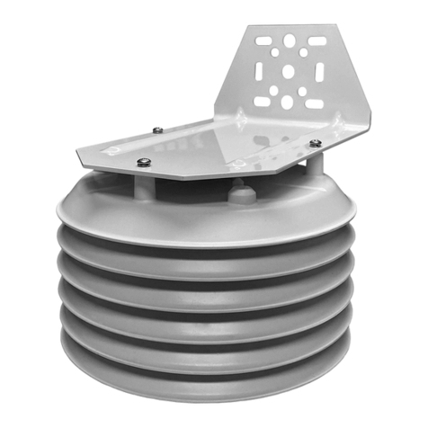
• The TempLinc sensor
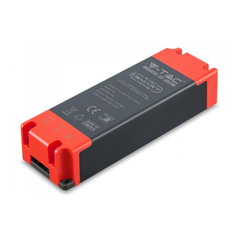
• PowerLinc II PowerLine Interface Module
• PowerLinc II connecting cable
• Double-sided foam tape and mounting screws
Please note that this PowerLinc II interface is
designed to only work with the TempLinc sensor.
While it resembles our regular # 1132B PowerLinc
II interface, the two are incompatible and not interchangeable. The included
PowerLinc Interface contains different circuitry and programming to support only the
TempLinc sensor. The AC outlet on the front of the PowerLinc II interface is a pass-
through outlet for any 120-volt electrical device. It does not have any automation
functions.
Installation
Locate the TempLinc in an area that has good airflow and is located near an electri-
cal power outlet. The TempLinc can be mounted either vertically or horizontally, for
best results it is recommended that a vertical position be used. TempLinc is not
weatherproof and should not be used outdoors or for measuring water temperature.
Doing so may shorten the life of the sensor module.
1. The TempLinc comes with double-sided tape to secure it to the surface. Once
the location is chosen, make sure the mounting surface is clean and free from
dust, dirt, and debris.
2. Remove the protective sheet from one side of the double-sided tape to expose
the adhesive portion and apply it to the back of the TempLinc
3. Remove the protective sheet from the other side of the double-sided tape to
expose the other adhesive portion and place it over the mounting surface and
press firmly to secure it.
4. With the TempLinc secured in placed, connect the cable between the
PowerLinc and the jack of the TempLinc.
Do not plug the PowerLinc in until instructed to do so in the programming section of
this manual.
Because of the way TempLinc communicates over the AC wires, it may be difficult to
have other modules on the same house code used by TempLinc. You may want to
study the signals sent between the TempLinc and your home automation control
program(s) to find addresses for other modules. Or, simply set-aside the entire
house code for TempLinc's exclusive use.
Quick Start Instructions
1. Un-plug the PowerLinc II from the AC outlet for 10 seconds
2. Plug in the PowerLinc II into the outlet and wait three seconds
3. Within one minute of plugging in the PowerLinc II, send the following:
i. Send the base house/unit code of the TempLinc three times in a row
ii. Send the house/unit code for the Operation Mode
(see Table 1 on page 7 for operating modes)
iii For Thermostat modes, send the set point using unit codes
(See page 7 for more detailed instructions) 3
1625_web.qxd 6/24/2004 1:11 PM Page 3

New Features in TempLincs with the PowerLinc II interface
With the changeover to the new PowerLinc II interface, we have taken some time to
implement some user-suggested improvements. Since most of the brains of the
TempLinc system are in the PowerLinc II interface, any TempLinc sensor and cable
will have these improvements when used with the PowerLinc II interface.
(Remember, the TempLinc must be used with a specially made and programmed
PowerLinc II interface.)
Status Request signals can be sent in any mode
Status Request commands are now accepted and responded to in any mode the
TempLinc is programmed into. Previously, TempLinc would only respond to Status
Request commands if it was programmed in the "Report on Request" mode.
PLC signals are now sent twice
To improve signal reliability, the TempLinc will send ON and OFF commands twice
(when set to one of the thermostat modes). Additionally, the TempLinc will hold off
transmitting if it detects signals on the powerline from other PLC transmitters. (This
is sometimes called Polite Mode or Signal Collision Avoidance.) By sending the sig-
nal twice, the odds are increased that a complete transmission of data will arrive at
the receiver(s).
Transmissions after a power failure
When the TempLinc is powered up (for the first time or after a power failure),
TempLinc will check the temperature and if it is beyond the programmed set point
(in the thermostat mode), it will send a PLC signal to activate the controlled device.
Send on Change mode now ignores small temperature changes
This was an improvement suggested by many of our users. TempLinc will no longer
send PLC signals if a small change in temperature is detected. Previously, when
TempLinc was in the Send on Change mode, it would send a PLC signal every time a
temperature change was detected. In some cases, this could cause a flood of PLC
signals and unnecessary cycling of equipment controlled due to TempLinc's temper-
ature reporting. With this improvement, the TempLinc will not send a PLC signal if
the temperature changes back to the previous temperature.
See Chart below
4
1625_web.qxd 6/24/2004 1:11 PM Page 4

Temperature sensing for Report on Change Modes changed
The TempLinc will now check for temperature changes every minute rather than
every eight milli-seconds. This change was requested because in some cases, the
TempLinc was detecting changes as a result of minor temperature disturbances.
For example, someone walks by the sensor or there is a sudden gust of airflow
across the sensor, the old TempLinc would have sent a flurry of PLC signals in
response to every change. When in the Thermostat Mode, it will still send an ON or
OFF the instant it senses a temperature change.
Programming and controlling the TempLinc
Using a Max-controller
The TempLinc will need to be programmed with a Maxi-Controller
(Smarthome #4020) or an equivalent transmitter capable of send-
ing Housecode and Unit Codes without ON or OFF commands. The
buttons are separated into Addresses and Command functions,
which allow it to send individual commands. Transmitters in which
one button is pressed to turn a load on or off WILL NOT WORK.
When using a Maxi-Controller or an equivalent transmitter, be care-
ful when pressing the buttons. Commands will be ignored if some
commands are not sent in the right sequence. "Fat-Fingering" or accidentally press-
ing the same button twice may prevent the programming from being accepted. This
same transmitter is also used for setting scenes, addresses, and other advanced
features in Smarthome plug-in modules, light switches, and KeypadLinc wall-mount-
ed transmitters.
For more info visit: http://www.smarthome.com/4020.html
Windows-based TempLinc Program
Smarthome has created a small Windows-based PC pro-
gram to help program and monitor TempLinc. It is avail-
able as a free download from the TempLinc product
page on Smarthome.com:
http://www.smarthome.com/1625.html
It requires the use of a Serial PowerLinc interface.
The program gives you access to all the features of the
TempLinc. It also includes step-by-step commands to
aid in the programming of the TempLinc.
Third-party programs
As of this manual's publication, we have found that the programs below offer some
support and control for the TempLinc.
• Home Control Assistant (version 4.15 and above)
• HomeSeer Home Automation Software
• Indigo Software for Mac (version 1.3.0 and above)
• Zeus Home Control (version 3.1 and above)
Please note: there are no guarantees that these programs operate flawlessly or that they will continue to
include support for TempLinc. Smarthome make no guarantees or endorsements of these products.
#4020 MMaxi-
Controller
5
1625_web.qxd 6/24/2004 1:11 PM Page 5

Modes of Operations
The TempLinc can be setup in a variety of different ways depending on the project's
needs. To make programming more of a simple task, decide ahead of time which
mode of operation the TempLinc is to work in. There are eight operation modes that
can be chosen among: Additionally, these modes can measure or report in the
Fahrenheit or Celsius temperature scales.
Report on Change
TempLinc will report the new room temperature whenever a change is detected.
TempLinc will send a house/unit code and preset dim (B15 - Predim6) that corre-
sponds to the current temperature. Refer to Table 2 for a list of temperatures and
their corresponding codes. It will also respond to Status Requests commands
Report on Request
TempLinc will report the room temperature whenever a status request signal is
received. Sending the house/unit code plus the house code/status request (B1 - B
Status Request) to TempLinc will return house/unit code and preset dim of the cur-
rent temperature. Refer to Table 2 for a list of temperatures and their corresponding
codes).
Thermostat (Cooling)
TempLinc will act like a thermostat in cooling mode. Set the temperature set point
by sending a house/unit code combination described in the programming section.
Once the temperature set point is programmed, TempLinc will send out its
house/unit code and house code + "ON" (B1 - BON) if the temperature is higher
than the set point or house code + "OFF" (B1 - BOFF) if the temperature is lower
than the set point.
Cooling Combination 1
This combination combines the report on change feature along with the thermostat
cooling mode feature.
Cooling Combination 2
This combination combines the report on request feature along with the thermostat
cooling mode feature.
Thermostat (Heating)
TempLinc will act like a thermostat in heating mode. Set the temperature set point
by sending a house/unit code combination described in the programming section.
Once the temperature set point is programmed, TempLinc will send out its
house/unit code and house code + "ON" (B1 - BON) if the temperature is lower than
the set point or house code + "OFF" (B1 - BOFF) if the temperature is higher than
the set point.
Heating Combination 1
This combination combines the report of change feature along with the thermostat
heating mode feature.
Heating Combination 2
This combination combines the report of request feature along with the thermostat
heating mode feature.
6
1625_web.qxd 6/24/2004 1:11 PM Page 6

Programming
With the mode of operation determined, the TempLinc can now be programmed.
Programming will require a PLC transmitter that can send separate unit and function
codes. A Maxi-transmitter, Smarthome #4020 or X10 #SC503 or PHC02 is ideal for
programming the TempLinc. All programmed settings are stored in an EEPROM and
will not be lost if the power is removed or disrupted.
1. Put TempLinc into programming mode by plugging the PowerLinc interface
module into a 120-volt wall receptacle.
2. Within one minute after plugging the PowerLinc into the wall, send the base
house/unit code of the TempLinc three times in a row (D5, D5, D5).
3. Set the operating mode from the table below by sending the house and unit
code (the house code is the same as the one used for the base address)
Code to Send Operation Mode Scale Example
House code + "1" Report on change Fahrenheit D1
House code + "2" Report on request Fahrenheit D2
House code + "3" Thermostat (cooling) Fahrenheit D3
House code + "4" Report on change and thermostat
cooling mode combination Fahrenheit D4
House code + "5" Report on request and thermostat
cooling mode combination Fahrenheit D5
House code + "6" Thermostat (heating) Fahrenheit D6
House code + "7" Report on change and thermostat
heating mode combination Fahrenheit D7
House code + "8" Report on request and thermostat
heating mode combination Fahrenheit D8
House code + "9" Report on change Celsius D9
House code + "10" Report on request Celsius D10
House code + "11" Thermostat (cooling) Celsius D11
House code + "12" Report on change and thermostat
cooling mode combination Celsius D12
House code + "13" Report on request and thermostat
cooling mode combination Celsius D13
House code + "14" Thermostat (heating) Celsius D14
House code + "15" Report on change and thermostat
heating mode combination Celsius D15
House code + "16" Report on request and thermostat
heating mode combination Celsius D16
Table 1
Example:
If the TempLinc was to be put in the report on request mode in Celsius scale and
the desired base address to be D5, send D5, D5, D5 and D10 within one minute
after power-up.
For all modes, other than the thermostat mode, programming is completed and
the TempLinc is ready for use. 7
1625_web.qxd 6/24/2004 1:11 PM Page 7

Programming(continued)
Setting the Set Point in the Thermostat Mode
An additional step is needed for thermostat mode, programming the temperature
set point. After sending the mode command, send a house/unit code combination
that corresponds to the temperature set point at which the TempLinc sends ON or
OFF signals. The first unit code sent is the first digit of the set point temperature
and the second unit code is the second digit. Unit codes 1 through 9 represent dig-
its 1 through 9, for 0 use unit code 10. The set point temperature is limited to a
positive two-digit number between 00 and 99. If the project requires the use of set
points above 99 degrees Fahrenheit, use the TempLinc in the Celsius mode.
Example:
To put the TempLinc in thermostat cooling mode with a set point of 78° in the
Fahrenheit scale and the base address to be L15, send L15, L15, L15, L3, L7, and
L8. The unit codes 7 and 8 will set the temperature to 78°F.
The hysteresis in thermostat mode is 2°F (1°C). In cooling mode, the thermostat
will shut off about 2° lower than the set point. In heating mode, the thermostat will
shut off about 2° higher than the set point.
Any time the TempLinc needs to be reprogrammed or updated, unplug PowerLinc
and leave it unplugged for about 10 seconds. Afterwards, plug the PowerLinc back
in and follow the programming procedure from the beginning.
TempLinc Temperature Reporting
When the TempLinc is in the Report on Change or Report on Request modes, it will
transmit a house/unit code and preset dim level to represent the temperature.
Table 2 shows the temperatures that correspond to each house/unit code and pre-
set dim. The Temperature to PLC Code Translation Table is directly supported by
many home automation systems.
Decoding the Current Temperature Sensed by TempLinc
1. Look at the house and unit code that the TempLinc transmitted. The house
code will match the base house code of the TempLinc and the unit code will
either be 11,12, 13, 14, 15, or 16
2. Select the column that matches the house/unit code sent by the TempLinc
3. Look at the preset dim that was transmitted by TempLinc and match it to the
preset dim value in the left column
4. Once matched, follow that row to the right until house/unit code column is
matched
5. The number that is in the box where the row and column meet is the tempera-
ture
8
1625_web.qxd 6/24/2004 1:11 PM Page 8

Preset Dim
Level
House
Code +
"11"
House
Code +
"12"
House
Code +
"13"
House
Code +
"14"
House
Code +
"15"
House
Code +
"16
0% -60 -28 4 36 68 100
3% -59 -27 5 37 69 101
6% -58 -26 6 38 70 102
10% -57 -25 7 39 71 103
13% -56 -24 8 40 72 104
16% -55 -23 9 41 73 105
19% -54 -22 10 42 74 106
23% -53 -21 11 43 75 107
26% -52 -22 12 44 76 108
29% -51 -19 13 45 77 109
32% -50 -18 14 46 78 110
35% -49 -17 15 47 79 111
38% -48 -16 16 48 80 112
42% -47 -15 17 49 81 113
45% -46 -14 18 50 82 114
48% -45 -13 19 51 83 115
52% -44 -12 20 52 84 116
55% -43 -11 21 53 85 117
58% -42 -10 22 54 86 118
61% -41 -9 23 55 87 119
65% -40 -8 24 56 88 120
68% -39 -7 25 57 89 121
71% -38 -6 26 58 90 122
74% -37 -5 27 59 91 123
77% -36 -4 28 60 92 124
81% -35 -3 29 61 93 125
84% -34 -2 30 62 94 126
87% -33 -1 31 63 95 127
90% -32 0 32 64 96 128
94% -31 1 33 65 97 129
97% -30 2 34 66 98 130
100% -29 3 35 67 99 131
Table 2 - Temperature to PLC Code Translation Table
The House code is the same as the base address house code.
Temperatures are read in both Fahrenheit and Celsius. 78°F will give House Code
+ "15" and preset dim 32%. 23°C will give House Code + "13" and preset dim 61%.
9
1625_web.qxd 6/24/2004 1:11 PM Page 9

Using TempLinc with
Smarthome Live
SmarthomeLive is a full-fea-
tured monitoring and control
application that lets you see
inside your home, receive e-
mails or text messages when
motion is detected, and
remotely control electronics,
from anywhere in the world
where you can access the
Internet.
Unlike other home monitoring
systems that only let you see
inside your house, or provide passive alerts when motion is detected,
SmarthomeLive is one of the only systems available that gives you on-command
control of your electronics. For just a few dollars a month, you'll be able to control
lights, turn the stereo on or off, or even tell your TiVo to record a show if you're held
up at the office and won't be home in time to watch it live.
SmarthomeLive is ready to
work with up to four TempLinc
sensors (each on a different
housecode). You can place
TempLincs in temperature
sensitive areas of your home.
For example, place one in
your basement to monitor for
potential freezes. Alerts can
be set up so that if the tem-
perature sensed by any
TempLinc exceeds a value
you've set, an Email will be
sent to you.
TempLinc Windows Desktop Application
This cool application is available to all SmarthomeLive reg-
istered users. It will display the temperatures from all your
TempLincs on your Windows Desktop without having to
login to SmarthomeLive. By setting the TempLincs to the
"Report on Change" mode, the temperature data will be
automatically routed via the Internet to your computer any-
where in the world. You may also query your thermostats to
ensure your temperature is up to date. This program works
for all operating systems that allow the desktop to be set as
a web page.
Please note that SmarthomeLive is an evolving product. These
screen captures and features described here may change. For the
latest information, please visit the SmarthomeLive web site at:
http://www.smarthomelive.com
10
1625_web.qxd 6/24/2004 1:12 PM Page 10

Using TempLinc in areas with extreme temperatures
The TempLinc sensor head can reliable measure temperatures from -60°F and
131°F. However, the PowerLinc Interface, which contains the processing electronics
of the TempLinc system is only rated to work between 32°F and 120°F. If the
PowerLinc Interface is exposed to temperature beyond its rated limit, the whole sys-
tem may lock-up, or report erratic data. Keep the PowerLinc Interface in an area
where the temperatures are between 32°F and 120°F for reliable operation. The
data cable between the sensor head and the PowerLinc Interface can be reliably
extended with Smarthome #1132E 12 ft. PowerLinc Extension Cable.
Having trouble....?
If you cannot resolve an issue you’re having with the TempLinc;
• Search our on-line knowledge base at: http://smarthome.custhelp.com
• Call our Technical Support Dept. at 949-221-9200
Suggestions and product feedback are welcome
If you would like to suggest a product improvement or tell us about your experience
with the TempLinc, we would like to hear from you. Our Engineering team monitors
the feedback we receive at Smarthome. Please send your comments to:
beta at smarthome dot com
Please note that we will not likely be able to respond to your message.
11
Invest in better Home
Automation Products
Unlike most electric items, many PLC-
based products haven't changed much
over the years.
Our Marketing and Customer Service teams surveyed our cus-
tomers, like you, and our engineers have invented new and bet-
ter wall switches and plug-in modules. We include more fea-
tures, higher load handling, and better signal sensitivity for a
superior user experience. While in some cases, they cost
more; we hope you'll agree that not having to replace a dead
module every couple years is worth the added expense and
reduced aggravation. Please visit a retailer or distributor for
the complete line of automation products from Smarthome
Design. Check out our web site at:
http://www.smarthome.com/smarthomedesignstore.html
KeypadLinc 6 with
450W integrated
dimmer
1625_web.qxd 6/24/2004 1:12 PM Page 11

About PowerLinc II’s Certification
The PowerLinc Interface has been thoroughly tested by ITS ETL SEMKO,
a nationally recognized independent third-party testing laboratory.
Products bearing North American ETL Listed mark signifies that the
product has been tested to and has met the requirements of a widely
recognized consensus of U.S. and Canadian product safety standards,
that the manufacturing site has been audited, and that the manufactur-
er has agreed to a program of quarterly factory follow-up inspections to
verify continued conformance.
Smarthome Limited Warranty
Smarthome warrants to the original consumer purchaser of this product that, for a period of two years
from the date of purchase, this product will be free from defects in material and workmanship and will
perform in substantial conformity to the description of the product in this Owner's Manual. This warranty
shall not apply to defects or errors caused by misuse or neglect.
If the product is found to be defective in material or workmanship or if the product does not perform as
warranted above during the warranty period, Smarthome will either repair it, replace it or refund the pur-
chase price, at its option, upon receipt of the product at the address below, postage prepaid, with proof of
the date of purchase and an explanation of the defect or error. The repair, replacement, or refund that is
provided for above shall be the full extent of Smarthome's liability with respect to this product.
For repair or replacement during the warranty period, call Smarthome customer service to receive an
RA# (return authorization number), properly package the product (with the RA# clearly printed on the
outside of the package) and send the product, along with all other required materials, to:
Smarthome
ATTN: Receiving Dept.
16542 Millikan Ave
Irvine, CA 92606-5027
Limitations:
THE ABOVE WARRANTY IS IN LIEU OF AND SMARTHOME DISCLAIMS ALL OTHER WARRANTIES,
WHETHER ORAL OR WRITTEN, EXPRESS OR IMPLIED, INCLUDING ANY WARRANTY OF MERCHANTABILI-
TY OR FITNESS FOR A PARTICULAR PURPOSE. ANY IMPLIED WARRANTY, INCLUDING ANY WARRANTY
OF MERCHANTABILITY OR FITNESS FOR A PARTICULAR PURPOSE, WHICH MAY NOT BE DISCLAIMED OR
SUPPLANTED AS PROVIDED ABOVE SHALL BE LIMITED TO THE ONE YEAR PERIOD OF THE EXPRESS
WARRANTY ABOVE. NO OTHER REPRESENTATION OR CLAIM OF ANY NATURE BY ANY PERSON SHALL
BE BINDING UPON SMARTHOME OR MODIFY THE TERMS OF THE ABOVE WARRANTY AND DISCLAIMER.
IN NO EVENT SHALL SMARTHOME BE LIABLE FOR SPECIAL, INCIDENTAL, CONSEQUENTIAL OR OTHER
DAMAGES RESULTING FROM THE POSSESSION OR USE OF THIS PRODUCT, INCLUDING WITHOUT LIMI-
TATION DAMAGE TO PROPERTY AND, TO THE EXTENT PERMITTED BY LAW, PERSONAL INJURY, EVEN IF
SMARTHOME KNEW OR SHOULD HAVE KNOWN OF THE POSSIBILITY OF SUCH DAMAGES.
Some states do not allow limitations on how long an implied warranty lasts and/or the exclusion or limi-
tation of damages, in which case the above limitations and/or exclusions may not apply to you. You may
also have other legal rights, which may vary from state to state.
SwitchLinc, KeypadLinc, SignaLinc, LampLinc, PowerLinc, ToggleLinc, BoosterLinc, ApplianceLinc,
ControLinc, TesterLinc, FilterLinc, ProbeLinc, TempLinc, TouchLinc, IR Linc & SmarthomeLive are
trademarked by Smarthome, Inc.
© Copyright 2004 Smarthome, 16542 Millikan Ave., Irvine, CA 92606-5027
800.SMART.HOME - 949.221.9200- www.smarthome.com
rev 062404
1625_web.qxd 6/24/2004 1:12 PM Page 12
Table of contents

