Smart Life EXTRALINK BRYZA ESF-40D-BL User manual

1
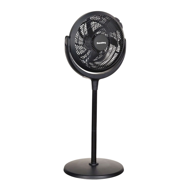
EXTRALINK BRYZA STANDING FAN 16” 40CM
Model: ESF-40D-BL
EN - USER MANUAL ----------------------------------------------------------------- 2
DE - BETRIEBSANLEITUNG --------------------------------------------------------- 6
PL - INSTRUKCJA OBSŁUGI ------------------------------------------------------- 10
ES - MANUAL DE INSTRUCCIONES --------------------------------------------- 14
IT - MANUALE ---------------------------------------------------------------------- 18
FR - INSTRUCTIONS D'UTILISATION ------------------------------------------- 22
CZ - NÁVOD K POUŽITÍ ------------------------------------------------------------ 24
TR - KULLANIM KILAVUZU --------------------------------------------------------28

2
EXTRALINK BRYZA STANDING FAN 16” 40CM
Model: ESF-40D-BL
USER MANUAL

3
1. Installers and Users please note:
These instructions should be read carefully and left with the user of the product for future
reference.
2. Assembly
1. Loosen the screws on the base bars. Cross the two bars as shown and align with the flange.
Secure with the four screws, and slider the base cover over the assembly.
2. Loosen the clamp screw but do not remove it, then slide the fan assembly down over the
inner tube, and tighten the tube to hold it in place.
3. Unscrew the plastic nut from the motor housing. Locate the rear guard on the motor
housing - the two holes in the guard align with the two round pegs on the motor housing. Push
the guard firmly into place and secure with the plastic nut.
4. Insert the motor shaft through the blades, aligning the pin on the motor shaft with the slot
on the back of the blades. Secure the blades in place with the spinner. Rotate anti-clockwise to
tighten - it has a left-handed thread.
5. Check that the blades are free to rotate.
6. Attach the logo badge to the front guard using the plastic clip supplied.
7. Attach the front guard to the rear guard using the clips built into the front guard.
8. Using a screwdriver, secure the two parts of the guard together with the screw and nut
provided.
WEEE Disposal and Recycling Information
All products bearing this symbol are waste electrical and electronic equipment
(WEEE as in directive 2012/19/EU) which should not be mixed with unsorted
household waste. Instead, you should protect human health and the environment
by handing over your waste equipment to a designated collection point for the
recycling of waste electrical and electronic equipment, appointed by the government or local
authorities. Correct disposal and recycling will help prevent potential negative consequences
to the environment and human health. Please contact the installer or local authorities for
more information about the location as well as terms and conditions of such collection points.

4
3. Description of device components
1 –Blades Guard
2 –Cover
3 –Blades
4 –Control Panel
5 –Telescopic Shaff
6 –Clamp Screw
7 –Height Adjustment
8 –Lower Shaft
9 –Base Cover
10 –Base Bars

5
4. Operation
- Plug the mains lead into mains socket.
- If connecting via an extension lead, make sure that the lead is rated at 3 Amps or more, and
that it is fully unwound.
- Use the height adjustment knob (see diagram on page 3) to adjust the tube to the optimum
height.
- Use the push-button switches to the speed required:
1. Low Speed = 3000 m3/h airflow
2. Medium Speed = 3300 m3/h airflow
3. High Speed = 3600 m3/h airflow
- Oscillation is selected by pressing the oscillation knob downwards, and switched off by
pulling it upwards
- It is normal for the motor to become warm in normal use.
- Unplug the appliance from the mains when not in use.
5. Product Safe
• This appliance can be used by children aged from 8 years and above and persons with
reduced physical, sensory or mental capabilities or lack of experience and knowledge if they
have been given supervision or instruction concerning use of the appliance in a safe way and
understand the hazards involved.
• Children shall not play with the appliance.
• Cleaning and user maintenance shall not be made by children without supervision.
• Do not use in close proximity to gas appliances
• Do not use unless correctly installed. Do not cover when in use.
• Do not place the mains lead beneath a carpet or rug.
• Do not use the appliance in locations where paint, petrol or other flammable liquids are used
or stored.
• Do no insert any object into the appliance through the grilles. This may damage the
appliance or result in overheating or electric shock.
• Do not use this appliance in the immediate surroundings of a bath, a shower or a swimming
pool.
• The appliance is fitted with an overload cut-out which will operate if the motor overheats or
is stalled. If this happens, disconnect from the mains supply immediately, and allow the motor
to cool down.
Importer:
BATNA Sp. z o.o.
ul. 1 Maja 23
42-202 Częstochowa
www.batna24.com

6
EXTRALINK BRYZA STANDLÜFTER 16” 40CM
Model: ESF-40D-BL
BETRIEBSANLEITUNG

7
1. Informationen für Benutzer:
Dieses Handbuch sollte sorgfältig gelesen und zum späteren Nachschlagen aufbewahrt
werden.
2. Montage des Produkts
1. Lösen Sie die Schrauben an beiden Elementen des Sockels(10). Die beiden Teile kreuzen und
ausrichten, den Ventilatorsockel(8) installieren und mit vier Schrauben befestigen. Schieben
Sie die Sockelabdeckung auf(9).
2. Lösen Sie die Klemmschraube an der Oberseite des Lüfters(6), aber ziehen Sie sie nicht
heraus, schieben Sie dann die Lüfterbaugruppe auf das Rohr und ziehen Sie die
Klemmschraube an, um sie zu befestigen.
3. Schrauben Sie die Kunststoffmutter vom Motorgehäuse ab. Setzen Sie die hintere
Abdeckung so auf das Motorgehäuse, dass die beiden Löcher in der Abdeckung mit den beiden
runden Stiften am Motorgehäuse übereinstimmen. Schieben Sie die Haube an ihren Platz und
sichern Sie sie mit der Kunststoffmutter.
4. Das Ventilatorlaufrad auf die Motorwelle aufsetzen und mit einer Mutter gegen den
Uhrzeigersinn sichern.
5. Prüfen Sie, ob sich die Messer frei drehen können.
6. Befestigen Sie die Logoplakette mit der mitgelieferten Kunststoffklammer an der
Frontabdeckung.
7. Befestigen Sie die vordere Abdeckung mit den in der vorderen Abdeckung integrierten
Klammern an der hinteren Abdeckung.
8. Befestigen Sie die beiden Teile der Abdeckung mit Hilfe eines Schraubendrehers mit der
mitgelieferten Schraube und Mutter.
WEEE-Informationen zur Entsorgung und zum Recycling
Alle mit diesem Symbol gekennzeichneten Produkte sind Elektroschrott und
Elektrogeräte (WEEE entsprechend EU-Richtlinie 2012/19/EU) und dürfen nicht mit
unsortiertem Haushaltsmüll vermischt werden. Schützen Sie stattdessen Ihre
Mitmenschen und die Umwelt, indem Sie Ihre zu entsorgenden Geräte an eine dafür
vorgesehene, von der Regierung oder einer lokalen Behörde eingerichtete Sammelstelle zum
Recycling von Elektroschrott und Elektrogeräten bringen. Eine ordnungsgemäße Entsorgung
und Recycling helfen, negative Auswirkungen auf die Gesundheit von Umwelt und Menschen
zu vermeiden. Wenden Sie sich bitte an den Installateur oder lokale Behörden, um
Informationen zum Standort und den allgemeinen Geschäftsbedingungen solcher
Sammelstellen zu erhalten.

8
3. Beschreibung der Gerätekomponenten
1 –Abdeckung
2 –Logoplakette
3 –Rotorblätter
4 –Bedienfeld
5 –Höhenverstellbares Rohr
6 –Feststellschraube
7 –Höhenverstellung
8 –Untere Lüfterhalterung
9 –Sockelabdeckung
10 –Basis

9
4. Hinweise zur Handhabung
- Stecken Sie das Netzkabel in die Steckdose.
- Wenn Sie das Gerät mit einem Verlängerungskabel anschließen, achten Sie darauf, dass das
Kabel für mindestens 3 A ausgelegt ist und vollständig ausgezogen ist.
- Verwenden Sie den Höheneinstellknopf (7), um das Rohr auf die optimale Höhe einzustellen.
- Mit den Drucktastenschaltern stellen Sie die gewünschte Geschwindigkeit ein:
1. niedrige Geschwindigkeit = 3000 m3/h Luftstrom
2. mittlere Geschwindigkeit = 3300 m3/h Luftstrom
3. hohe Geschwindigkeit = 3600 m3/h Luftdurchsatz
- Die Oszillation/Lüfterdrehung wird durch Drücken des Oszillationsknopfes nach unten
eingeschaltet und durch Ziehen nach oben ausgeschaltet.
- Es ist normal, dass sich der Motor erwärmt, wenn das Gerät in Betrieb ist.
- Trennen Sie das Gerät vom Netz, wenn es nicht benutzt wird.
5. Leitlinien zur Sicherheit
• Das Gerät kann von Kindern ab 8 Jahren und Personen mit eingeschränkten körperlichen,
sensorischen oder geistigen Fähigkeiten oder mangelnder Erfahrung und Kenntnis benutzt
werden, wenn sie beaufsichtigt werden oder Anweisungen zum sicheren Gebrauch des Geräts
erhalten haben und die damit verbundenen Risiken verstehen.
• Kinder sollten nicht mit dem Gerät spielen.
• Die Reinigung und Wartung darf nicht von unbeaufsichtigten Kindern durchgeführt werden.
• Nicht in der Nähe von Gasgeräten verwenden.
• Verwenden Sie das Gerät nicht, wenn es nicht ordnungsgemäß zusammengebaut wurde.
Während des Gebrauchs nicht abdecken.
• Legen Sie das Netzkabel nicht unter einen Teppich.
• Verwenden Sie das Gerät nicht in Bereichen, in denen Farbe, Benzin oder andere brennbare
Flüssigkeiten verwendet oder gelagert werden.
• Stecken Sie keine Gegenstände durch das Abdeckgitter in das Gerät. Dies kann zu Schäden
am Gerät, Überhitzung oder Stromschlag führen.
• Benutzen Sie dieses Gerät nicht in der Nähe einer Badewanne, einer Dusche oder eines
Schwimmbeckens.
• Das Gerät ist mit einem Überlastungsschalter ausgestattet, der auslöst, wenn der Motor
überhitzt oder stehen bleibt. Trennen Sie in diesem Fall das Gerät sofort vom Stromnetz und
lassen Sie den Motor abkühlen.
Importer:
BATNA Sp. z o.o.
ul. 1 Maja 23
42-202 Częstochowa
www.batna24.com

10
EXTRALINK BRYZA WENTYLATOR STOJĄCY 16” 40CM
Model: ESF-40D-BL
INSTRUKCJA OBSŁUGI

11
1. Informacja dla użytkowników:
Niniejszą instrukcję należy dokładnie przeczytać i pozostawić w celu wykorzystania jej w
przyszłości.
2. Montaż produktu
1. Należy poluzować śruby na obu elementach podstawy(10). Skrzyżować oba elementy i
wyrównać, zamontować podstawę wentylatora(8), zabezpieczyć czterema śrubami. Nasunąć
pokrywę podstawy(9).
2. Należy poluzować śrubę zaciskową górnej części wentylatora(6), ale jej nie wyciągać,
następnie wsuń zespół wentylatora na rurkę i dokręć śrubę zaciskową, aby zamontować go na
miejscu.
3. Odkręcić plastikową nakrętkę z obudowy silnika. Umieścić tylną osłonę na obudowie silnika
tak, aby dwa otwory w osłonie pokrywały się z dwoma okrągłymi kołkami na obudowie silnika.
Wcisnąć osłonę na miejsce i zabezpieczyć plastikową nakrętką.
4. Zamontować wirnik wentylatora na wale silnika oraz zabezpieczyć nakrętką, obracając w
kierunku przeciwnym do ruchu wskazówek zegara.
5. Należy sprawdzić, czy ostrza mogą się swobodnie obracać.
6. Przymocować plakietkę z logo do osłony przedniej za pomocą dostarczonego plastikowego
klipsa.
7. Przymocować osłonę przednią do osłony tylnej za pomocą zacisków wbudowanych w osłonę
przednią.
8. Używając śrubokręta, należy przymocować obie części osłony ze sobą za pomocą
dostarczonej śruby i nakrętki.
Informacje dotyczące utylizacji i recyklingu WEEE
Wszystkie produkty oznaczone tym symbolem są uznane za odpady sprzętu
elektrycznego i elektronicznego (WEEE zgodnie z Dyrektywą 2012/19/UE) i nie mogą
być wyrzucane po zakończeniu okresu użytkowania wraz z innymi odpadami. W celu
ochrony zdrowia ludzi oraz środowiska naturalnego należy przekazać zużyty sprzęt
do wyznaczonego punktu utylizacji wyznaczonego przez instytucje rządowe lub lokalne.
Prawidłowe usunięcie zużytego produktu pomaga w zapobieganiu potencjalnym negatywnym
skutkom oddziaływania na środowisko
naturalne i zdrowie ludzi. Więcej informacji można uzyskać w urzędzie lokalnym lub od
instalatora.

12
3. Opis elementów urządzenia
1 –Osłona
2 –Plakietka z logo
3 –Łopatki wirnika
4 –Panel kontrolny
5 –Rura do regulacji wysokości
6 –Śruba mocująca
7 –Regulacja wysokości
8 –Dolny wspornik wentylatora
9 –Pokrywa podstawy
10 –Podstawa

13
4. Instrukcja obsługi
- Podłączyć przewód zasilający do gniazda sieciowego.
- W przypadku podłączania za pomocą przedłużacza należy upewnić się, że przewód ma
dopuszczalne natężenie 3A lub więcej i że jest całkowicie rozwinięty.
- Użyć pokrętła regulacji wysokości (7), aby ustawić rurę na optymalnej wysokości.
- Za pomocą przełączników przyciskowych ustawić wymaganą prędkość:
1. Niska prędkość = 3000 m3/h przepływu powietrza
2. Średnia prędkość = 3300 m3/h przepływu powietrza
3. Wysoka prędkość = 3600 m3/h przepływu powietrza
- Oscylację/obrót wentylatora włącza się naciskając pokrętło oscylacji w dół, a wyłącza
pociągając je do góry.
- Normalnym zjawiskiem jest nagrzewanie się silnika podczas użytkowania urządzenia.
- Należy odłączyć urządzenie od sieci, gdy nie jest używane.
5. Wytyczne dotyczące bezpieczeństwa
• Urządzenie może być używane przez dzieci w wieku od 8 lat wzwyż oraz osoby o
ograniczonych możliwościach fizycznych, sensorycznych lub umysłowych lub osoby nie
posiadające doświadczenia i wiedzy, jeżeli otrzymały one nadzór lub instrukcje dotyczące
bezpiecznego użytkowania urządzenia i rozumieją związane z tym zagrożenia.
• Dzieci nie powinny bawić się urządzeniem.
• Czyszczenie i konserwacja nie mogą być wykonywane przez dzieci bez nadzoru.
• Nie stosować w pobliżu urządzeń gazowych.
• Nie należy korzystać z urządzenia, jeśli nie zostało prawidłowo zmontowane. Nie przykrywać
w trakcie użytkowania.
• Nie umieszczaj przewodu zasilającego pod dywanem lub wykładziną..
• Nie używaj urządzenia w miejscach, gdzie używane lub przechowywane są farby, benzyna lub
inne łatwopalne ciecze.
• Nie wolno wkładać żadnych przedmiotów do urządzenia przez kratkę osłony. Może to
spowodować uszkodzenie urządzenia, przegrzanie lub porażenie prądem.
• Nie należy używać tego urządzenia w pobliżu wanny, prysznica lub basenu.
• Urządzenie jest wyposażone w wyłącznik przeciążeniowy, który zadziała w przypadku
przegrzania lub zatrzymania silnika. W takim przypadku należy natychmiast odłączyć
urządzenie od sieci elektrycznej i pozwolić silnikowi ostygnąć.
Importer:
BATNA Sp. z o.o.
ul. 1 Maja 23
42-202 Częstochowa
www.batna24.com

14
EXTRALINK BRYZA VENTILADOR DE PIE 16” 40CM
Modelo: ESF-40D-BL
MANUAL DE INSTRUCCIONE

15
1 Información para los usuarios:
Lea atentamente este manual y guárdelo para futuras consultas.
2. Montaje del producto
1. Afloje los tornillos de ambos elementos de la base(10). Cruce las dos piezas y alinee, instale
la base del ventilador(8), asegure con cuatro tornillos. Deslice la tapa de la base(9).
2. Afloje el tornillo de apriete de la parte superior del ventilador(6) pero no lo extraiga, luego
deslice el conjunto del ventilador sobre el tubo y apriete el tornillo de apriete para ajustarlo en
su sitio
3. Desenrosque la tuerca de plástico de la carcasa del motor. Coloque la tapa trasera en el
alojamiento del motor de forma que los dos orificios de la tapa coincidan con los dos
pasadores redondos del alojamiento del motor. Empuje el capó en su sitio y fíjelo con la tuerca
de plástico.
4. Coloque el impulsor del ventilador en el eje del motor y fíjelo con una tuerca, girando en
sentido contrario a las agujas del reloj.
5. Compruebe que las cuchillas pueden girar libremente.
6. Fije la placa del logotipo a la cubierta frontal utilizando el clip de plástico suministrado.
7. Fije la tapa delantera a la tapa trasera mediante las abrazaderas incorporadas en la tapa
delantera.
8. Con un destornillador, fije las dos partes de la tapa con el tornillo y la tuerca suministrados.
Directiva RAEE de información de eliminación y reciclaje
Todos los productos que llevan este símbolo son residuos de aparatos eléctricos y
electrónicos (RAEE según la directiva 2012/19/UE) que no deben mezclarse con
residuos domésticos sin clasificar. En su lugar, debe proteger la salud humana y el
medio ambiente entregando sus equipos de desecho a un punto de recogida para el
reciclaje de residuos de equipos eléctricos y electrónicos, designado por el gobierno o las
autoridades locales. La eliminación y el reciclado correctos ayudarán a evitar posibles
consecuencias negativas para el medio ambiente y la salud humana. Póngase en contacto con
el instalador o con las autoridades locales para obtener más información sobre la ubicación y
las condiciones de dichos puntos de recogida.

16
3. Descripción de los componentes del dispositivo
1 –Funda
2 –Placa con logotipo
3 –Palas del rotor
4 –Panel de control
5 –Tubo de ajuste de altura
6 –Tornillo de fijación
7 –Ajuste de la altura
8 –Soporte inferior del ventilador
9 –Cubierta base
10 –Base
4. Manual de instrucciones

17
- Enchufa el cable de alimentación a la toma de corriente.
- Si la conexión se realiza mediante un alargador, asegúrese de que el cable tiene una
capacidad nominal de 3 A o más y de que está totalmente extendido.
- Utilice el botón de ajuste de altura (7) para ajustar el tubo a la altura óptima.
- Utilice los pulsadores para ajustar la velocidad deseada:
1. Baja velocidad = 3000 m3/h de caudal de aire
2. Velocidad media = caudal de aire de 3300 m3/h
3. Alta velocidad = 3600 m3/h de caudal de aire
- La oscilación/rotación del ventilador se conecta pulsando el botón de oscilación hacia abajo y
se desconecta tirando de él hacia arriba.
- Es normal que el motor se caliente cuando la unidad está en uso.
- Desconecte el aparato de la red eléctrica cuando no lo utilice.
5. Normas de seguridad
- El aparato puede ser utilizado por niños a partir de 8 años y por personas con capacidades
físicas, sensoriales o mentales limitadas o con falta de experiencia y conocimientos, si han
recibido supervisión o instrucciones sobre el uso seguro del aparato y comprenden los riesgos
que conlleva.
- Los niños no deben jugar con el aparato.
- La limpieza y el mantenimiento no deben ser realizados por niños sin supervisión.
- No utilizar cerca de aparatos de gas.
- No utilice el aparato si no ha sido montado correctamente. No cubrir durante el uso.
- No coloque el cable de alimentación debajo de una alfombra o moqueta.
- No utilice el aparato en zonas donde se utilice o almacene pintura, gasolina u otros líquidos
inflamables.
- No introduzca ningún objeto en la unidad a través de la rejilla de la cubierta. Esto puede
provocar daños en el aparato, sobrecalentamiento o descargas eléctricas.
- No utilice este aparato cerca de una bañera, ducha o piscina.
- El aparato está equipado con un interruptor de sobrecarga que se activará si el motor se
sobrecalienta o se para. Si esto ocurre, desconecte inmediatamente el aparato de la red
eléctrica y deje que el motor se enfríe.
Importador:
BATNA Sp. z o.o.
ul. 1 Maja 23
42-202 Częstochowa
www.batna24.com

18
EXTRALINK BRYZA VENTILATORE A STELO 16” 40CM
Modello: ESF-40D-BL
MANUALE

19
1 Informazioni per gli utenti:
Il presente manuale deve essere letto attentamente e conservato per future consultazioni.
2. Assemblaggio del prodotto
1.Allentare i bulloni su entrambi gli elementi della base(10). Incrociare i due pezzi e allinearli,
installare la base del ventilatore(8), fissandola con quattro viti. Inserire il coperchio della
base(9).
2. Allentare la vite del morsetto superiore della ventola (6) senza estrarla, quindi far scorrere il
gruppo della ventola sul tubo e stringere la vite del morsetto per inserirlo in posizione.
3. Svitare il dado di plastica dall'alloggiamento del motore. Posizionare il coperchio posteriore
sull'alloggiamento del motore in modo che i due fori sul coperchio coincidano con i due perni
rotondi sull'alloggiamento del motore. Spingere il coperchio in posizione e fissarlo con il dado
di plastica.
4. Montare la girante del ventilatore sull'albero del motore e fissarla con un dado, girando in
senso antiorario.
5. Verificare che le pale del ventilatore possano ruotare liberamente.
6. Fissare il badge del logo al coperchio anteriore utilizzando la clip di plastica in dotazione.
7. Fissare il coperchio anteriore al coperchio posteriore utilizzando i morsetti incorporati nel
coperchio anteriore.
8. Con un cacciavite, fissare le due parti del coperchio con la vite e il dado in dotazione.
Informazioni sullo smaltimento e sul riciclaggio dei RAEE
Tutti i prodotti contrassegnati da questo simbolo sono rifiuti di apparecchiature
elettriche ed elettroniche (RAEE in base alla direttiva 2012/19/UE) che non devono
essere smaltiti assieme a rifiuti domestici non differenziati. Al contrario, è necessario
proteggere l’ambiente e la salute umana consegnando i rifiuti a un punto di raccolta
autorizzato al riciclaggio di rifiuti di apparecchiature elettriche ed elettroniche, predisposto
dalla pubblica amministrazione o dalle autorità locali. Lo smaltimento e il riciclaggio corretti
aiutano a prevenire conseguenze potenzialmente negative all’ambiente e alla salute umana.
Contattare l’installatore o le autorità locali per ulteriori informazioni sulla sede e per i termini e
le condizioni di tali punti di raccolta.

20
3. Descrizione dei componenti dell'apparecchiatura
1 - Scudo
2 - Targa con logo
3 - Pale del rotore
4 - Pannello di controllo
5 - Tubo di regolazione dell'altezza
6 - Bullone di fissaggio
7 - Regolazione dell'altezza
8 - Supporto della ventola inferiore
9 - Coperchio della base
10 - Base
Table of contents
Languages:
Other Smart Life Fan manuals
Popular Fan manuals by other brands
MAHA
MAHA Air 1 Original operating instructions
Nederma
Nederma Series 591 instruction manual
Lasko
Lasko 2680M Important instructions & operating manual
ACME
ACME BreezeMaster BDR36 W/WSS Installation & maintenance instructions
Fanelite
Fanelite KYT-30B user manual

ENERVEX
ENERVEX RS 009 Installation & operating manual
LUCCI Air
LUCCI Air AIRFUSION AKMANI Installation, operation, maintenance & warranty information
Maico
Maico HDR 12 Mounting and operating instructions
Greenheck
Greenheck Combination Fire Smoke Damper FSD-211 Specification sheet
HOMCOM
HOMCOM 824-043V70 Assembly & instruction manual
Hunter
Hunter 42753-01 Owner's guide and installation manual

Dantherm
Dantherm HCV 300 manual

