Smart Living SmartModem100 User manual
SmartModem100 1
Instructions
SmartModem100 è il modem necessario per
programmare e controllare le centrali INIM della serie
SmartLiving da telefono.
SmartModem100 permette quindi di programmare e
verificare tutti i parametri di funzionamento della
centrale. La scrittura e la lettura di tutti i parametri è
possibile solo se la centrale ha tutte le aree disinserite
(con la sola eccezione del registro eventi che può
essere letto anche con le aree inserite) e se l'utente ha
abilitato la teleassistenza.
Collegamento del
modem
SmartModem100 deve essere collegato,
tramite il cavo USB in dotazione, al PC sul
quale deve essere installato il software
INIM-SmartLeague. La linea telefonica va
collegata al connettore PSTN.
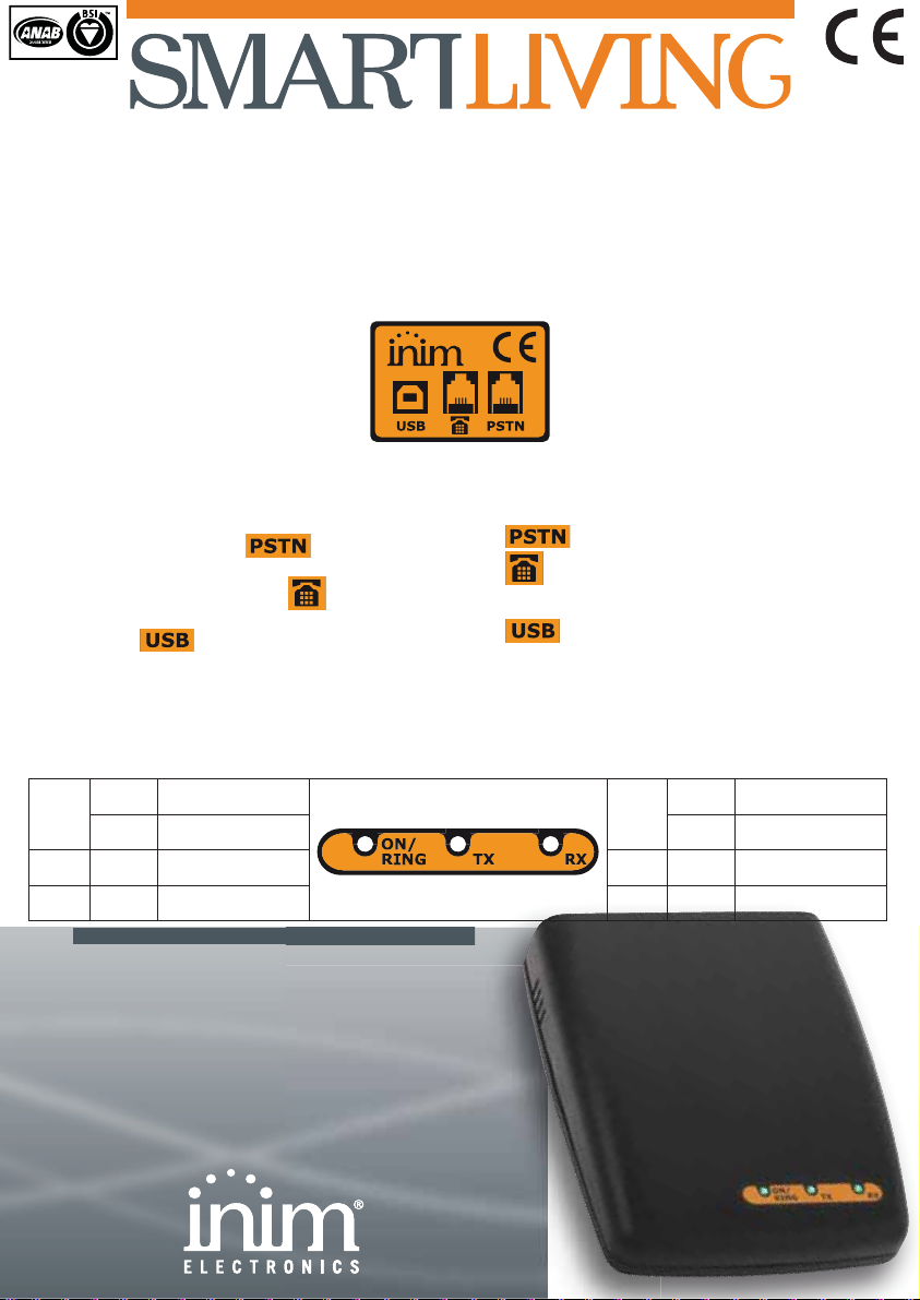
Nella parte posteriore del modem sono presenti, da
sinistra a destra, 3 plugs di connessione indicati
dall’etichetta a fianco.
1. Collegare il plug telefonico proveniente dalla presa
telefonica al connettore del modem.
2. Collegare eventuali apparecchi telefonici a valle
del modem ovvero alla presa del modem.
3. Collegare il cavo USB proveniente dal computer
alla presa del modem.
Il modem viene alimentato non appena viene collegato
il cavo USB al computer.
Indicazioni dei LED
I LED posti nella parte anteriore del modem indicano i
seguenti stati:
SmartModem100 is the modem necessary to program
and monitor the INIM control panels of the
SmartLiving series remotely by phone.
SmartModem100 allows you to program and verify all
the parameters of the control panel. It is possible to
write and read all the parameters only if all the
partitions are disarmed (with the exception of event
log that can be read with the partitions armed) and if
the teleservice is enabled.
Connecting the
modem
SmartModem100 must be connected via
the USB cable (supplied) to the PC which
must have the INIM-SmartLeague software
installed. The phone line must be
connected to the PSTN port.
The product label (on the back of the device) shows
you how to employ the 3 connectors located on the
back of the modem.
1. connects to the landline telephone cable.
2. connects to the main telephone device (in
this way, all telephone devices will be connected
downstream to the modem).
3. connects to the computer USB port.
The modem is powered on once the USB connections
is complete.
LED signalling
The LEDs on the front of the modem signal the
following conditions:
ON/
RING
acceso
fisso Modem alimentato
ON/
RING
On
solid Modem power OK
lampeg
giante Squillo riconosciuto blinking Incoming-ring
recognition
TX
lampeg
giante Dati in uscita dal
modem
TX
blinking Outgoing data
RX
lampeg
giante Dati in entrata dal
modem
RX
blinking Incoming data
SmartModem100
Istruzioni
Instructions
2SmartModem100
Istruzioni
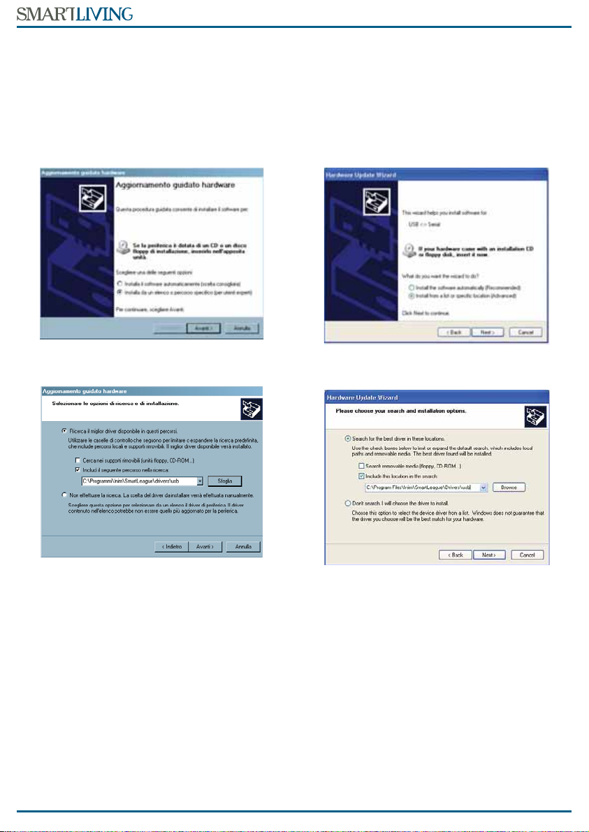
Installazione del driver
Il driver viene fornito (ma non installato) con il
software SmartLeague.
La prima volta che il modem viene collegato al
computer, se quest’ultimo non ha installato il driver
appropriato, Windows chiederà di installarlo.
Di seguito sono indicati i passi per installare
correttamente il driver.
Nella finestra qui sotto selezionare:
Installa da un elenco o percorso specifico (per utenti esperti)
Se SmartLeague è installato su un computer dotato di
Windows XP™, selezionare il percorso:
C:\Programmi\Inim\SmartLeague\drivers\usb
Se SmartLeague è installato su un computer dotato di
Windows Vista™ o Seven™, selezionare il percorso:
C:\Programmi\Inim\SmartLeague\drivers\usb-vista
A questo punto il driver è stato installato quindi ogni
successivo collegamento del modem al computer non
richiederà più questa procedura.
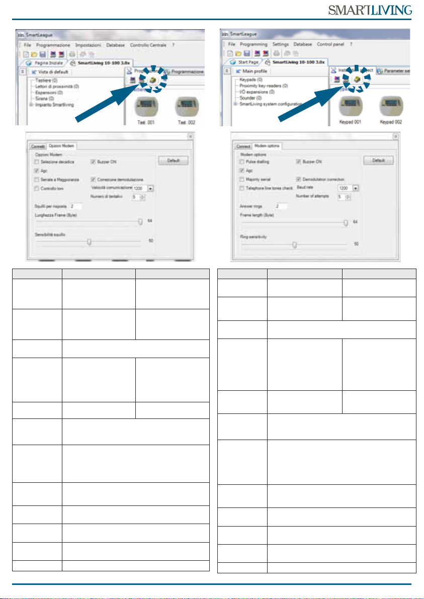
Collegamento alla centrale
via SmartModem100
1. Lanciare il software SmartLeague.
2. Accedere alla scheda “Progettazione” e premere il
pulsante indicato dalla freccia in figura.
3. Nella finestra che appare, selezionare la scheda
Opzioni Modem (vedi figura dopo) e leggere (pul-
sante “Leggi Opzioni”) o scrivere (pulsante “Salva
Opzioni”) le opzioni.
Installing the driver
The appropriate driver can be found (uninstalled) with
the SmartLeague software.
If you attempt to connect the modem to your
computer without first installing the driver, Windows
will request its installation.
Work carefully through the following steps to install
the driver.
Working from the window below, select:
Install from a list or a specific location (Advanced)
If you are working on a computer with Windows XP™
operating system, select:
C:\Program Files\Inim\SmartLeague\Drivers\usb
If you are working on a computer with Windows
Vista™ or Seven™ operating system, select:
C:\Program Files\Inim\SmartLeague\Drivers\usb-vista
The selected method installs the appropriate driver on
your computer, therefore, it is not necessary to install
it for each “modem-to-computer” connection.
Connecting to the control
panel via SmartModem100
1. Launch the SmartLeague software.
2. Access the “Installation project” page then press
the button indicated by the arrow in the figure.
3. Select Modem options on the window which
appears (refer to the following figure), then
upload (via “Upload” button) or download (via
“Download” button) the options.
SmartModem100 3
Instructions
OPZIONE
SE SELEZIONATA SE NON SELEZIONATA
Selezione
decadica
La composizione del
numero telefonico
viene effettuata ad
impulsi
La composizione del
numero telefonico
viene effettuata a toni
DTMF
Agc
Viene effettuato
l’adattamento
automatico alla linea
telefonica
Seriale a
maggioranza
Lasciare selezionata questa opzione
Controllo
toni
Viene effettuato il
controllo dei toni di
occupato, invito a
selezionare e fuori
servizio della linea
telefonica
Buzzer ON
Il buzzer del modem è
abilitato Il buzzer del modem è
disabilitato
Correzione
demodula
zione
Lasciare selezionata questa opzione
Velocità
comunica
zione
Selezionare la velocità scegliendo tra 1200,
600, 300 e V21.
Diminuire progressivamente la velocità
qualora si verificassero numerosi errori
durante la comunicazione
Numero di
tentativi
Numero di tentativi di comunicazione che il
modem effettua con la centrale remota prima
di segnalare l’errore
Squilli per
risposta
Numero di squilli dopo i quali il modem
risponde ad una chiamata entrante
Lunghezza
frame
Con il cursore, regolare il numero massimo di
bytes per frame.
Sensibilità
squillo
Con il cursore, regolare la sensibilità al
riconoscimento dello squillo
Default
Pulsante per il ripristino dei dati di fabbrica
OPTION
IF SELECTED IF UNSELECTED
Pulse
dialling
The device will dial
in touch tone
T
he device will dial
in DTMF mode
Agc
T
he device will adapt
automatically to the
telephone line
Majority
serial
Do not unselect this option
Telephone
lines tone
check
T
he device will check
for the engaged,
line-down and dial-
ling tones and will
dial only after reco-
gnition of the dial-
ling tone
Buzzer ON
T
he modem buzzer
will provide audible
signals
T
he modem buzzer
will be silent
Demodula
tion
correction
Do not unselect this option
Baud rate
Select the desired transmission speed –
1,200, 600, 300 or V21.
If errors occur during transmissions, you must
try to find the most suitable transmission
speed by lowering the selected value
progressively.
Number of
attempts
Number of attempts of communication
between the modem and the remote control
panel before reporting the fault.
Answer
rings
N
umber of rings the modem must allow
before answering incoming calls
Frame
lenght
R
egulate the number of bytes per frame
by means of the curso
r
Ring
sensitivity
Regulate the ring-recognition sensibility
by means of the cursor
Default
Button to restore factory data.
4SmartModem100
Istruzioni
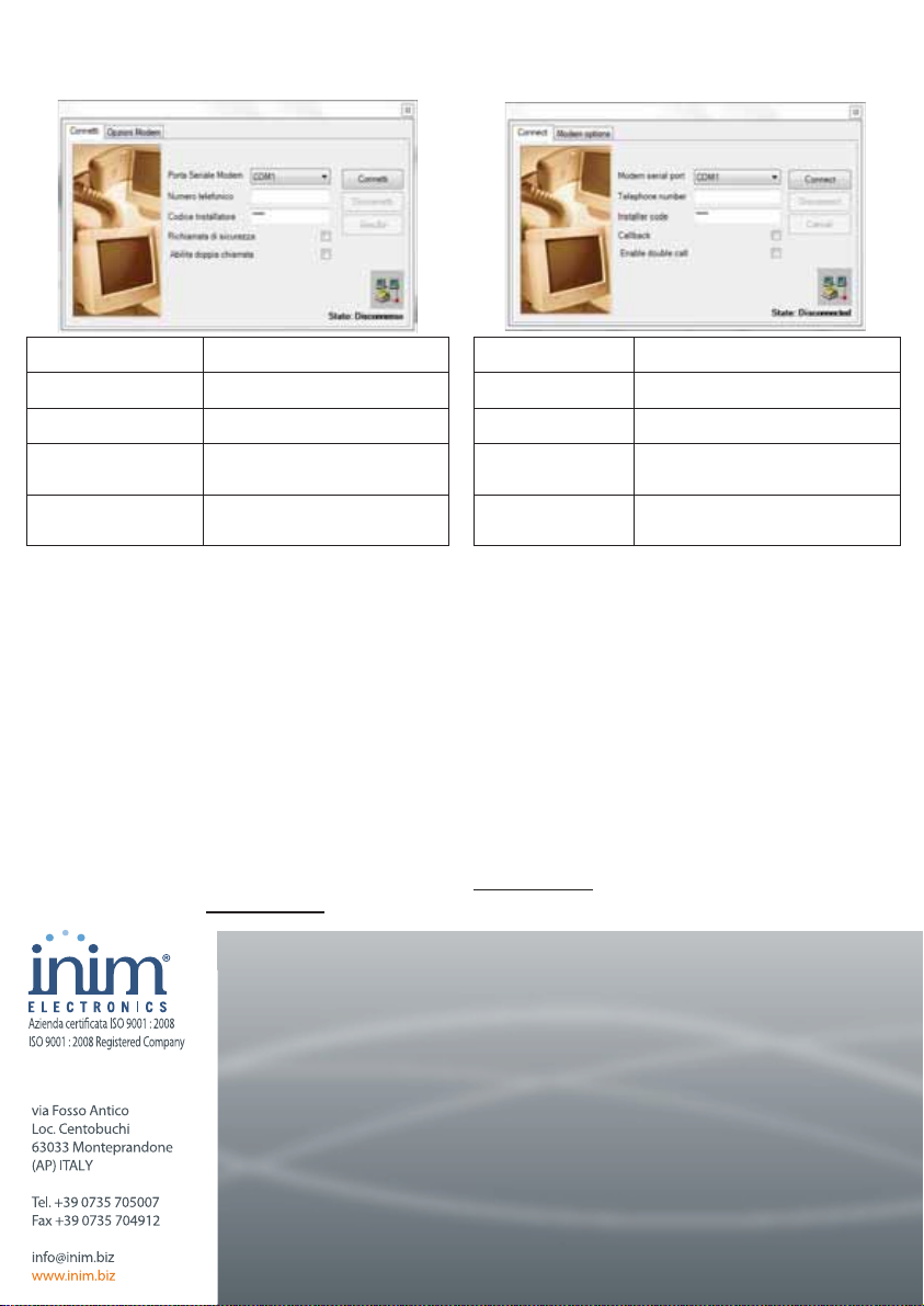
4. Selezionare la scheda Connetti (vedi figura sotto)
ed impostare i parametri.
Terminate le impostazioni sopra descritte, premere il
pulsante
“Connetti”
per salvare le opzioni impostate ed
avviare la connessione del modem alla centrale; una
volta effettuata la connessione nell’angolo in basso a
destra della figura qui sopra, l’indicazione dello stato
commuterà da
“Disconnesso”
a
“Connesso”
e si
potranno quindi utilizzare tutte le pagine e sezioni del
software per leggere/scrivere i parametri della centrale.
5. Premere il pulsante “Disconnetti” per terminare la
teleassistenza.
Informativa sulla
conformità alla direttiva
1999/5/CE (R&TTE)
Con la presente INIM ELECTRONICS S.R.L. dichiara
che SmartModem100 è conforme ai requisiti essenziali
ed alle altre disposizioni pertinenti stabilite dalla
direttiva 1999/5/CE.
Le dichiarazioni di conformità dei dispositivi citati sono
reperibili presso l’URL: www.inim.biz
Porta Seriale Modem
E’ la porta seriale cui è connesso il
modem
Numero telefonico
E’ il numero telefonico della
centrale cui collegarsi
Codice Installatore
E’ il PIN del codice installatore
della centrale cui collegarsi
Richiamata di
sicurezza
Selezionarla se si vuole la funzione
“Richiamata di sicurezza” (Manuale
di Installazione SmartLiving)
Abilita doppia
chiamata
Se anche in centrale è impostata la
doppia chiamata, il modem
effettua due chiamate alla centrale
4. Click-on the Connect tab (refer to the following
figure) and configure the modem.
When you have completed all the operations, press the
Connect button to save the options and initiate the
“modem-to panel” connection. Once the connection is
established, the status (indicated on the bottom left of
the screen) will switch from “Disconnected” to
“Connected” and you will be allowed to work on the
software and view/change the control panel
parameters.
5. Press the Disconnect button to end the session.
Directive 1999/5/CE
(R&TTE) compliance
Hereby INIM ELECTRONICS S.R.L. declares that the
SmartModem100 is in compliance with the essential
requirements and other relevant provisions of
Directive 1999/5/CE.
The full declarations of conformity of the above-
mentioned devices are available at URL:
www.inim.biz
Modem serial port
S
elect the port the modem is con-
nected t
Telephone number
T
elephone number of the control
panel the modem must connect to
Installer code
Installer code PIN of the control
panel the modem must connect to
Callback
R
equired, select the “Callback”
function (SmartLiving Installation
Manual for details)
Enable double call
If the control panel has the option
“double call” enabled, the modem
makes two calls to the control panel
DCMIINIESMODEM-R110-20101020


