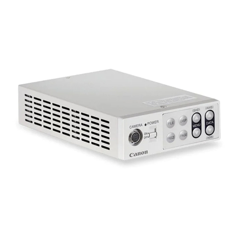
SMART-SCAN MAGSAFE 785-093 User manual

SMARTSCANMAGSAFE785093INSTALLATIONSHEETGUIDE
CD229/2307071
MAGSAFE785093(4MAGNETCONTROLUNIT)
INSTALLATIONSHEET(CD233/240806)
A Unpacking
q Removeallpackagingmaterialandretainit
q Locateandkeepthedeliverynote
q Inspectallitemsfortransitdamage
q Matchgoodssuppliedtothosespecifiedonthedeliverynote
q KeeptheInstallationSheetinasafeplace
EachMagsafesystemsuppliedwouldnormallyinclude:
q ControlUnit
q Installationsheet
q Servicequestionnaireform
Storagerequirements
q Humidity<95%
q Temperaturerangebetween20° Cand+70°C

SMARTSCANMAGSAFE785093INSTALLATIONSHEETGUIDE
CD229/2307072
B Dimensions
ControlunitprotectionratingIP40.Thecontrolboxisnormallymountedin
anIP40compatibleenvironment.Ithassixglandedconnectorsandone8
wayconnector.Dimensions230x145x60mm.Mountingisprovidedvia4x
M6bolts.

SMARTSCANMAGSAFE785093INSTALLATIONSHEETGUIDE
CD229/2307073
C ConnectionDiagramandPCBLayout

SMARTSCANMAGSAFE785093INSTALLATIONSHEETGUIDE
CD229/2307074
1TB ThisprovidestheuserconnectionfortheOutput
SwitchingDevice,providingthefailsafeoutputsfor
connectiontothemachinecontrolsystem.
SW1 Dipswitchselectorfortherundowntimers,magnet
typeselectionandparitybitchecksetting.
Magnetconnection
board
Terminalconnectionsfor1to4monitoredmagnets,
dipswitchsettingsforselectingthenumberof
magnetsrequiredandtheelectronicstatusoutput
drivers.
EStopBoard Thisprovidestheemergencystop,ExternalDevice
Monitoring(EDM)connectionsandpowersupply
connection.
LEDStatusOutputs Statusoutputsformagnet,accesscondition(Run,
Wait&Enter),powerandsafetyoutputs.
MagnetExtenderBoard EStopBoard
1TB
SW1
LEDStatusOutputs

SMARTSCANMAGSAFE785093INSTALLATIONSHEETGUIDE
CD229/2307075
Note:TheEstopboardisusedforconnectingpowertothesystem
eveniftheEstopfunctionisnotbeingused.
1TB–UserConnectionforOSD1and2
1TB1 InternalConnection,DoNotUse
(+24VDC)
1TB2 InternalConnection,DoNotUse
(Ground)
1TB3 InternalConnection,DoNotUse
(0V)
1TB4 InternalConnection,DoNotUse
(KeyA)
1TB5 InternalConnection,DoNotUse
(KeyB)
1TB6 InternalConnection,DoNotUse
(COMnotused)
1TB7 InternalConnection,DoNotUse
(RUN,RedLEDindicator)
1TB8 InternalConnection,DoNotUse
(WAIT,YellowLEDindicator)
1TB9 InternalConnection,DoNotUse
(ENTER,GreenLEDindicator)
1TB10 OSD1–OutputSwitchingDeviceProvidethefailsafeoutputs
forconnectiontothemachinecontrolsystem.Connectterminals1TB10and
1TB11toonechannelofthemachine’sstopcircuitry.Outputsarevoltage
freecontacts. Maximumswitchingcurrentis1Aat 110VAC
1TB11 OSD1–(see1TB10)
1TB12 OSD2–OutputSwitchingDeviceProvidethefailsafeoutputs
forconnectiontothemachinecontrolsystem.Connectterminals1TB12and
1TB13toonechannelofthemachine’sstopcircuitry.Outputsarevoltage
freecontacts. Maximumswitchingcurrentis1Aat 110VAC
1TB13 OSD2–(see1TB12)

SMARTSCANMAGSAFE785093INSTALLATIONSHEETGUIDE
CD229/2307076
StatusIndication–785093
MainPCBBoard&LocalAccessController
KEYSWITCH
POSITION CONDITION
POWER
MAGNET
KEYSW
(A)
KEYSW
(B)
RUN
WAIT
ENTER
SAFE
OUTPUTS
LEDCOLOURSONPCBRED RED RED RED RED YEL GRN GRN
LEDCOLOURSONLOCAL
ACCESSCONTROLLERRED YEL GRN
LEDNUMBERONPCBD14 D25 D15 D16 D18 D19 D20 D17
ENTER GATE
CLOSED * * *
ENTER GATE
OPEN * * *
RUN GATE
OPEN * * * * *
RUN GATE
CLOSED * * * * * *
FROMRUN
TOENTER
DURING
RUNDOWN
PERIOD
* * *
RUN LOCKOUT
CONDITION * * * * * * *
* LEDSTEADYON * LEDFLASHING
MagnetExtenderBoard
TheredLEDSontheextenderboardlight
upwhentheindividualmagnetisinaclosed
positionandgoesoffwhenthemagnetis
open.
IndividualredLEDoutputsareprovidedon
theboard,asshownopposite,representing
magnets1through4fromlefttoright,D6=
magnet1,D8=magnet2,D10=magnet3
andD12=magnet4.

SMARTSCANMAGSAFE785093INSTALLATIONSHEETGUIDE
CD229/2307077
D14
D18
D19
D20
D17
D25
D15
D16
MainPCBBoardshowing
positioningoftheStatusLEDs
LocalAccessControllershowing
theStatusLEDs

SMARTSCANMAGSAFE785093INSTALLATIONSHEETGUIDE
CD229/2307078
D MechanicalInstallation
TheLocalAccessControllermustbepositionedsothatthedangerareacan
beseentobeclearofpersonsbeforethesystemisactivated.Atypicalgate
entrysystemwillhaveamagnetmountedatboththetopandbottomofthe
gate.Themagnetscomewithaflexiblemountingkitasstandardforeaseof
installationandalignment.

SMARTSCANMAGSAFE785093INSTALLATIONSHEETGUIDE
CD229/2307079
E SW1DipSwitchSettings
Rundowntimer
TherundowntimercontrolstheperiodoftimethatthecontrollerisinAmber
condition(magnet‘on’safetyoutput‘off’). Thetwotimersmustbesetthe
same.Thetimerallowstimeforthemachinetocometoasafecondition
beforethedoorscanbeopened.
Rundowntimerselectionismadeviadipswitches1and2.Timingoptionsare
0,2,8and32seconds.Thesystemisdualcircuitsothereare2rundown
timerstoset.Thedipswitchintheuppositionindicatesthatthesettinghas
beenselected.Therundowntimercontrolstheperiodoftimethatthelocal
accesscontrollerisinanAmbercondition(magnet‘on’safetyoutput‘off’).
Thetimerallowstimeforthemachinetocometoasafeconditionbeforethe
doorscanbeopened.
1 2 Rundowntimeinseconds
0
X2
X8
X X32
Dipswitches3to7arefactorysetforthestandard63mmplatedmagnets
(785070M),dipswitch4intheupposition.Dipswitch8isusedforsettingthe
evenparitycheck.
SetEvenParity
Switch8istheparityswitch.Theswitchsettingsaremadefailsafewiththis
switch.Thecontrollerscounthowmanyofthe8switchesareintheup
position.Thismustbeanevennumber.Intheexampleshownabove,dip
Note:Pleaseensuredipswitch4isintheuppositionanddipswitch8
hasbeensetcorrectly,seeSetEvenParitysectionbelow.

SMARTSCANMAGSAFE785093INSTALLATIONSHEETGUIDE
CD229/23070710
switch4isselectedmakingtheinitialselectionanoddnumber,thereforedip
switch8needstobeintheuppositiontomakethetotalnumberofswitches
selectedandevennumber.
Ifthenumberofswitchesintheuppositionequalsanevennumberthenparity
switch8mustbeinthedownposition.Ifthenumberofswitchesintheup
positionequalsanoddnumberthenparityswitch8mustbeintheupposition.
Havingsettheswitchesinthisway,ifanyswitchsubsequentlyfails,eitheron
oroff,theparitywillgotooddandthefaultwillbedetected.
F Specification
Providesspecification
informationforthe785B093
controlunit.
Note:Iftheparitycheckissetincorrectly,orchangedwhilethecontrol
unitisinoperationthesystemwillgointoanonoperationalcondition.

SMARTSCANMAGSAFE785093INSTALLATIONSHEETGUIDE
CD229/23070711
Magnetconnectionboard
showing4magnetsconnected
Magnetconnectionboardshowing
magnetdipswitchselector
G MagnetExtenderBoard
MagnetConnection
Themagnetsareconnectedviablocksof4terminalsallocatedto1TB,2TB,
3TBand4TB.Eachblockof4terminalsequalstheconnectionsfor1magnet.
Startingfrom1TBonthelefthandsidethemagnetwiresareconnectedinthe
followingcoloursequence,1TB1=Brown,1TB2=White,1TB3=Blueand
1TB4=Black.Thissequenceisrepeatedacross2TB,3TBand4TB
dependingonhowmanymagnetsarebeingused.Ifthemagnetsarenot
connectedinthissequencethesystemwillgointoaLockoutcondition.
Thereddipswitchblockisusedtoselectthenumberofmagnetswhichare
beingmonitored,14.Adipswitchsetintheuppositionindicatesthatithas
beenselected.

SMARTSCANMAGSAFE785093INSTALLATIONSHEETGUIDE
CD229/23070712
1 2 3 4 Numberofmagnetsbeingmonitored
1
X X2
X X3
X X4
IndividualredLEDoutputsareprovidedon
theboard,asshownopposite,representing
magnets1through4fromlefttoright,D6=
magnet1,D8=magnet2,D10=magnet3
andD12=magnet4.
StatusOutputDrivers
Themagnetconnectionboardalso
determineswhichmagnetsareinaclosed
position(forvisualindicationpurposes).This
informationisfedtotheLEDindicatorsasshown
aboveandisalsoavailableasa24VDCstatus
outputsignalfordrivingaPLCinput(highorlow)
toindicatemagnetstatus.Theconnectionis
madevia4terminalssituatedatTB5inthetop
righthandcorneroftheextenderboard,starting
atthetopwithmagnet1throughtomagnet4asshown.Thecurrentcapacity
oftheoutputsis20mAperchannel.
Note:The785071M(36mm)and785070M(63mm)magnetscannot
beusedonthesamecontrolbox.

SMARTSCANMAGSAFE785093INSTALLATIONSHEETGUIDE
CD229/23070713
H EStopBoard
TheEstopboardisfittedasstandardandallowstheusertoconnectan
externalemergencystopdevicetotheMagsafecontrolunit.Activationofthe
Estopremovespowertothecontrolunitandmagnets.TheEstopboardis
usedforconnectingpowertothesystemeveniftheEstopfunctionisnot
beingused.
TheEmergencystopfunctionisselectedviathejumpersJ1andJ2ontheE
stopboardshownabove.PositionthejumperonJ2iftheEstopfunctionis
requiredoronJ1ifnotrequired.
EstopboardshowingjumpersJ1andJ2
Note:Inadditiontotheseare2otherjumperslocateddirectlyabovethe
maincontrolboard.Pleasesetthesejumperstothe‘ON’positionaswell
iftheEstopfunctionisrequired.Positionpin1and2=‘ON’andposition
pin2and3=‘OFF’.ThejumpersonboththemainPCBboardandtheE
stopboardmustbeinthesamecondition,eitherEstopselectedornot
selected.

SMARTSCANMAGSAFE785093INSTALLATIONSHEETGUIDE
CD229/23070714
Note:Aninternalcircuitmonitorsforshortcircuitsandswitching
disparitybetweenthetwoinputchannels.Iftheinputsdonot
switchtogether(within100msofeachother)thesystemwillgo
intoalockoutcondition.Thisconfigurationmeetsthe
requirementsfor‘controlreliability’andcannotbeusedina
singlechannelconfiguration.
TB1isthelocationfortheuserterminalconnections1through13,positioned
alongthebottomoftheEStopboard.
1TB1 +24VDCAregulatedpowersupplyisrequired,2.5ARipple
<10%(diodeprotected)Protectwitha4A250Vfuse. Thepowersupplymust
bestabilisedwithnotmorethan3%variationoverthetemperaturerangeof
thesupply.Thisisbecausethevoltagesuppliedtothemagnetisnot
stabilisedinsidethecontrolbox.
2TB1 Ground
3TB1 0V
4TB1 Connectonechannelofthemachinesemergencystopcircuit
betweenterminals4TB1and5TB1andthesecondchannelbetween
terminals6TB1and7TB1.
5TB1 (see4TB1above)
6TB1 (see4TB1above)
7TB1 (see4TB1above)
8TB1 KeyA(ignoreifusingtheSmartscanLocalAccessController)
9TB1 KeyA(ignoreifusingtheSmartscanLocalAccessController)
10TB1 KeyB(ignoreifusingtheSmartscanLocalAccessController)
11TB1 KeyB(ignoreifusingtheSmartscanLocalAccessController)
12TB1 ExternalDeviceMonitor(EDM)Normallyclosedswitch
contacts,inseriesfromtheexternalpowerswitchingdevicesareconnected
acrossterminals12TB1and13TB1.Themonitoringcircuitchecksthatthe
powerswitchingdevicesbothdeenergiseatthesametimetheMagsafe
controlunitsafetyoutputswitchesdeenergise.Ifoneorbothofthepower
switchingdevicesfailtodeenergiseatthistimetheMagsafecontrolunitgoes
intoalockoutcondition,turningalloutputswitchesoff.

SMARTSCANMAGSAFE785093INSTALLATIONSHEETGUIDE
CD229/23070715
Note:Inaddition,JumperJ3locatedat3TBinthe
bottomrighthandcornerofthemaincontrol
board,asshownoppositeneedstobesettothe
‘ON’positioniftheEDMfunctionisrequired.
Positionpin1and2=‘ON’andpositionpin2and
3=‘OFF’
Toresetfromalockoutconditionitisnecessarytoremovethe24VDCsupply
fromtheMagsafecontrolunitandthenreapply.IftheEDMcircuitisnotused
ensurethejumperissettothe‘OFF’position.
13TB1 (see12TB1above)
WhenanEmergencystopiscleareditisnecessarytousetheRun/Enter
selectorswitchtoresetthecontrolunit.E.g.turntheselectorswitchfromRun
toEnterandbacktoRunagain.
I Commissioning
Fig.Ishowsthe
operationschartforthe
Magsafesystem.
q Beforeinstallation
readandunderstand
theInstallation
Sheetprovided.Pay
particularattention
toCandD.
q Everymonthcheck
theentireinstallation
payingparticular
attentiontoCandD.
q Iftheequipmentfailstooperateasintendedchecktheelectrical
connectionsasshowninC.

SMARTSCANMAGSAFE785093INSTALLATIONSHEETGUIDE
CD229/23070716
J Repairanddisposal
Fig.JoutlinestheprocedureforreturningaSmartscanproduct.
Ifafaultoccursthatcannotberesolvedortheequipmentisdamagedreturn
thesystemtothenearestSmartscandistributororSmartscanLtd.Indicatethe
natureofthefaultandthesymptomsdisplayedontheformprovided.

SMARTSCANMAGSAFE785093INSTALLATIONSHEETGUIDE
CD229/23070717
APPENDIX1
UserconnectionswhennotusingthestandardSmartscanLocalAccess
Controller(785080)withControlUnit785093
1TB–Userinput/outputterminalsandpowersupply
1TB1 FactorySet(+24VDC)
1TB2 FactorySet(Ground)
1TB3 FactorySet(0V)
1TB4 FactorySet(KeyA)
1TB5 FactorySet(KeyB)
1TB6 COM(Linkto0V,on1TB3)
1TB7 RUN,(RedLEDindicatorD18.
Contactratedat2A,+24VDCfor
drivingthecustomer’sdevice).
1TB8 WAIT,(YellowLEDindicatorD19.
Contactratedat2A,+24VDCfor
drivingthecustomer’sdevice).
1TB9 ENTER,(Green
LEDindicatorD20.
Contactratedat2A,
+24VDCfordriving
thecustomer’s
device).
1TB10 OSD1–Output
SwitchingDeviceProvidethefailsafeoutputsforconnectiontothemachine
controlsystem.Connectterminals1TB10and1TB11toonechannelofthe
machine’sstopcircuitry.Outputsarevoltagefreecontacts. Maximum
switchingcurrentis1Aat110VAC
1TB11 OSD1–(see1TB10)
1TB12 OSD2–OutputSwitchingDeviceProvidethefailsafeoutputs
forconnectiontothemachinecontrolsystem.Connectterminals1TB12and
1TB13toonechannelofthemachine’sstopcircuitry.Outputsarevoltage
freecontacts.Maximumswitchingcurrentis 1Aat 110VAC
1TB13 OSD2–(see1TB12)

SMARTSCANMAGSAFE785093INSTALLATIONSHEETGUIDE
CD229/23070718
Note:Aninternalcircuitmonitorsforshortcircuitsandswitching
disparitybetweenthetwoinputchannels.Iftheinputsdonot
switchtogether(within100msofeachother)thesystemwillgo
intoalockoutcondition.Thisconfigurationmeetsthe
requirementsfor‘controlreliability’andcannotbeusedina
singlechannelconfiguration.
EStopBoard
1TB1 +24VDCAregulatedpowersupplyisrequired,2.5ARipple
<10%(diodeprotected)Protectwitha4A250Vfuse. Thepowersupplymust
bestabilisedwithnotmorethan3%variationoverthetemperaturerangeof
thesupply.Thisisbecausethevoltagesuppliedtothemagnetisnot
stabilisedinsidethecontrolbox.
2TB1 Ground
3TB1 0V
4TB1 Connectonechannelofthemachinesemergencystopcircuit
betweenterminals4TB1and5TB1andthesecondchannel
betweenterminals6TB1and7TB1.
5TB1 (see4TB1above)
6TB1 (see4TB1above)
7TB1 (see4TB1above)
8TB1 KeyA(ConnecttoKeyswitch/Selectorswitch,Closed=‘ON’,it
isnecessarytoswitchbothKeyAandBtogetherorthesystem
willgointoaLockoutcondition)
9TB1 KeyA(as8TB1above)
10TB1 KeyB(ConnecttoKeyswitch/Selectorswitch,Closed=‘ON’,it
isnecessarytoswitchbothKeyAandBtogetherorthesystem
willgointoaLockoutcondition)
11TB1 KeyB(as8TB1above)
12TB1 ExternalDeviceMonitor(EDM)Normallyclosedswitch
contacts,inseriesfromtheexternalpowerswitchingdevicesareconnected
acrossterminals12TB1and13TB1.Themonitoringcircuitchecksthatthe
powerswitchingdevicesbothdeenergiseatthesametimetheMagsafe
controlunitsafetyoutputswitchesdeenergise.Ifoneorbothofthepower
switchingdevicesfailtodeenergiseatthistimetheMagsafecontrolunitgoes
intoalockoutcondition,turningalloutputswitchesoff.

SMARTSCANMAGSAFE785093INSTALLATIONSHEETGUIDE
CD229/23070719
Note:Inaddition,JumperJ3locatedat3TBinthe
bottomrighthandcornerofthemaincontrol
board,asshownoppositeneedstobesettothe
‘ON’positioniftheEDMfunctionisrequired.
Positionpin1and2=‘ON’andpositionpin2and
3=‘OFF’
Toresetfromalockoutconditionitisnecessarytoremovethe24VDCsupply
fromtheMagsafecontrolunitandthenreapply.IftheEDMcircuitisnotused
ensurethejumperissettothe‘OFF’position.
13TB1 (see12TB1above)
WhenanEmergencystopiscleareditisnecessarytousetheRun/Enter
selectorswitchtoresetthecontrolunit.E.g.turntheselectorswitchfromRun
toEnterandbacktoRunagain.
Popular Control Unit manuals by other brands
DeZurik
DeZurik APCO CVS-250 instruction manual
Feig Electronic
Feig Electronic OBID i-scan ID ISC.MAT-A Installation
Dometic GROUP
Dometic GROUP WAECO MagicSpeed MS-BE3 Installation and operating manual
Digi
Digi MiniCore RCM5700 Series user manual
Festo
Festo CPX-CM-HPP Description

Burkert
Burkert 2301 Series quick start
Nordson
Nordson Auto-Flo II Customer product manual
Johnson Controls
Johnson Controls A19ZBC Series Technical bulletin

AMES
AMES Maxim M300 Series Installation, Service, Repair Kits, Maintenance
Mitsubishi Electric
Mitsubishi Electric MELSEC iQ-R C Programming manual

GEM
GEM ZRSK operating instructions
TUYA
TUYA WB2L datasheet
