bonitron M3699 User manual

Model M3699
Voltage Limiter Module
Customer Reference Manual

Bonitron, Inc.
2
Bonitron, Inc.
Nashville, TN
An industry leader in providing solutions for AC drives.
ABOUT BONITRON
Bonitron designs and manufactures quality industrial electronics that improve the reliability of
processes and variable frequency drives worldwide. With products in numerous industries, and
an educated and experienced team of engineers, Bonitron has seen thousands of products
engineered since 1962 and welcomes custom applications.
With engineering, production, and testing all in the same facility, Bonitron is able to ensure its
products are of the utmost quality and ready to be applied to your application.
The Bonitron engineering team has the background and expertise necessary to design, develop,
and manufacture the quality industrial electronic systems demanded in today’s market. A strong
academic background supported by continuing education is complemented by many years of
hands-on field experience. A clear advantage Bonitron has over many competitors is combined
on-site engineering labs and manufacturing facilities, which allows the engineering team to have
immediate access to testing and manufacturing. This not only saves time during prototype
development, but also is essential to providing only the highest quality products.
The sales and marketing teams work closely with engineering to provide up-to-date information
and provide remarkable customer support to make sure you receive the best solution for your
application. Thanks to this combination of quality products and superior customer support,
Bonitron has products installed in critical applications worldwide.

Bonitron, Inc.
3
AC DRIVE OPTIONS
In 1975, Bonitron began working with AC inverter drive specialists at synthetic fiber plants to
develop speed control systems that could be interfaced with their plant process computers. Ever
since, Bonitron has developed AC drive options that solve application issues associated with
modern AC variable frequency drives and aid in reducing drive faults. Below is a sampling of
Bonitron’s current product offering.
WORLD CLASS PRODUCTS
Undervoltage Solutions
Overvoltage Solutions
Uninterruptible Power for Drives
(DC Bus Ride-Thru)
Voltage Regulators
Chargers and Dischargers
Energy Storage
Braking Transistors
Braking Resistors
Transistor/Resistor Combo
Line Regeneration
Dynamic Braking for Servo Drives
Common Bus Solutions
Portable Maintenance Solutions
Single Phase Power Supplies
3-Phase Power Supplies
Common Bus Diodes
Capacitor Formers
Capacitor Testers
Power Quality Solutions
Green Solutions
12 and 18 Pulse Kits
Line Regeneration

M3699
4
This page intentionally left blank.

Table of Contents
5
1. INTRODUCTION..........................................................................................................................7
1.1. Who Should Use This Manual...................................................................................................... 7
1.2. Purpose and Scope........................................................................................................................ 7
1.3. Manual Version and Change Record............................................................................................7
Figure 1-1: M3699 ..........................................................................................................................................7
1.4. Symbol Conventions Used in this Manual and on Equipment.....................................................8
2. PRODUCT DESCRIPTION............................................................................................................9
2.1. Related Products...........................................................................................................................9
2.2. Part Number Breakdown ..............................................................................................................9
Figure 2-1: Example of Part Number Breakdown...........................................................................................9
2.3. General Specifications................................................................................................................10
Table 2-1: General Specifications .................................................................................................................10
2.4. General Precautions and Safety Warnings .................................................................................10
3. INSTALLATION INSTRUCTIONS................................................................................................11
3.1. Environment ...............................................................................................................................11
3.2. Unpacking................................................................................................................................... 11
3.3. Mounting ....................................................................................................................................11
Figure 3-1: M3699 Mounting Orientation.....................................................................................................11
3.4. Wiring and User Connections..................................................................................................... 12
Table 3-1: Wiring Specifications...................................................................................................................12
3.5. Fusing.........................................................................................................................................12
Figure 3-2: M3699 Wiring Connections .......................................................................................................13
4. OPERATION..............................................................................................................................15
4.1. Functional Description ...............................................................................................................15
4.2. Features....................................................................................................................................... 15
4.2.1. Voltage Present Indicator ..................................................................................................................15
4.3. Startup......................................................................................................................................... 15
4.3.1. Pre-Power Checks .............................................................................................................................15
4.3.2. Startup Procedure And Checks..........................................................................................................15
5. MAINTENANCE AND TROUBLESHOOTING...............................................................................17
5.1. Troubleshooting..........................................................................................................................17
5.1.1. LED Indicator Not Lit .......................................................................................................................17
5.1.2. No Output..........................................................................................................................................17
5.2. Technical Help –Before You Call .............................................................................................17
6. ENGINEERING DATA................................................................................................................19
6.1. Ratings........................................................................................................................................19
Table 6-1: M3699 Ratings Table...................................................................................................................19
6.2. Efficiency / Power Consumption................................................................................................19
Figure 6-1: M3699 Efficiency Chart .............................................................................................................19
6.3. Dimensions and Mechanical Drawing........................................................................................20
Figure 6-2: M3699 Chassis Dimensional Outline .........................................................................................20
Figure 6-3: M3699 Voltage Limiter Block Diagram.....................................................................................21

M3699
6
This page intentionally left blank.

User’s Manual
7
1. INTRODUCTION
1.1. WHO SHOULD USE THIS MANUAL
This manual is intendedfor use by anyone who is responsiblefor integrating, installing,
maintaining, troubleshooting, or using this equipment.
Please keep this manual for future reference.
1.2. PURPOSE AND SCOPE
This manual is a user’s guide for the Model M3699. It will provide the user with the
necessary information to successfully install, integrate, and use the M3699.
In the event of any conflict between this document and any publication and/or
documentation related to the application, the latter shall have precedence.
1.3. MANUAL VERSION AND CHANGE RECORD
Rev 00a is the initial printing of the manual for the M3699.
Added efficiency chart to engineering data in Rev 00b.
The manual template was updated in Rev 00c.
Updates to Tables 2-1 and 6-1, Figures 3-2 and 6-3 were made in Rev 01a.
Updates to Section 2.1 Related Products and to Figure 3-2 in Rev 01b.
Update to Section 4.1, Figure 3-2, and Figure 6-3 was made in Rev 01c.
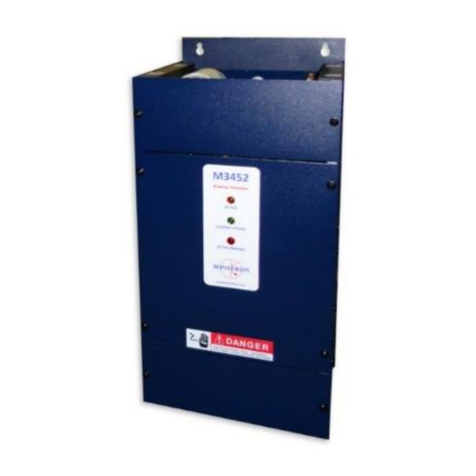
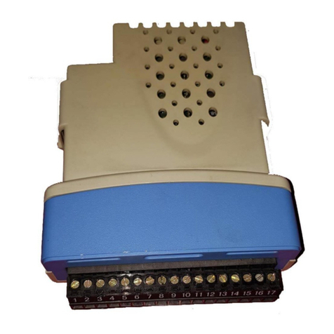
Figure 1-1: M3699

M3699
8
1.4. SYMBOL CONVENTIONS USED IN THIS MANUAL AND ON
EQUIPMENT
Earth Ground or Protective Earth
AC Voltage
DC Voltage
DANGER!
DANGER: Electrical hazard - Identifies a statement that indicates
a shock or electrocution hazard that must be avoided.
DANGER!
DANGER: Identifies information about practices or circumstances
that can lead to personal injury or death, property damage, or
economic loss.
CAUTION!
CAUTION: Identifies information about practices or circumstances
that can lead to property damage, or economic loss. Attentions
help you identify a potential hazard, avoid a hazard, and
recognize the consequences.
CAUTION!
CAUTION: Heat or burn hazard - Identifies a statement regarding
heat production or a burn hazard that should be avoided.

User’s Manual
9
2. PRODUCT DESCRIPTION
The M3699 Voltage Limiter accepts a wide DC input voltage range up to 1000VDC. The
voltage limiter reduces the input to a range acceptable by a common 24VDC isolated
switching power supply. The M3699 works as a regulator to provide non isolated 175VDC
referenced to the negative power rail.
2.1. RELATED PRODUCTS
M7001 MODULE
The M7001 is a 24VDC power supply with a wide range (190-1000VDC) input. For
backup systems using capacitors or batteries, such as Bonitron Uninterruptible Power
for Drives, the M7001 can provide backup to local control systems, sensors or
networks with 24VDC.
2.2. PART NUMBER BREAKDOWN
Figure 2-1: Example of Part Number Breakdown
BASE MODEL NUMBER
The Base Model Number for the voltage limiter modules is M3699.
CONTINUOUS POWER RATING
The continuous power rating is a 3 digit number to represent the power able to be
supplied by the M3699 in Watts.
For example, 135 represents 135 W.
CHASSIS SIZE
The chassis size used for the M3699 is DIN.
M3699
135
DIN
BASE MODEL NUMBER
CONT.POWER RATING
CHASSIS SIZE

M3699
10
2.3. GENERAL SPECIFICATIONS
Table 2-1: General Specifications
PARAMETER
SPECIFICATION
DC Input Operating Range
125-1000 VDC
DC Output Voltage
175 VDC Nominal
Power (Continuous)
135 W
Overload Capability
150% for 60 seconds
Indicators
Status LED
Cooling
Convection
Operating Temp
0C to 50C
Storage Temp
-20C to 65C
Humidity
Below 90%, non-condensing
Atmosphere
Free of corrosive gas or conductive dust
2.4. GENERAL PRECAUTIONS AND SAFETY WARNINGS
DANGER!
HIGH VOLTAGES MAY BE PRESENT !
NEVER ATTEMPT TO OPER ATE THIS PRODUCT WIT H THE
ENCLOSURE COVER REMOVED!
NEVER ATTEMPT TO SERVICE THIS PRODUCT WIT HOUT
FIRST DISCONNECTING POWER TO AND FROM THE UNIT!
ALWAYS ALLOW ADEQU ATE TIME FOR RESIDUAL
VOLTAGES TO DRAIN BEFORE REMOVING THE
ENCLOSURE COVER!
FAILURE TO HEED THESE WARNINGS MAY
RESULT IN SERIOUS BODILY INJURY OR DEATH!
CAUTION!
NO USER-SERVICEABLE PARTS AR E CONTAINED WITHIN
THIS PRODUCT .INOPERABLE UNITS SHOU LD BE
REPLACED OR RETURNED FOR EVALUAT ION AND/OR
REPAIR BY QUALIFIED TECHNICIANS.
ANY QUESTIONS AS TO APPLICATION, INSTALLATION, OR SERVICE SAFETY
SHOULD BE DIRECTED TO THE EQUIPMENT SUPPLIER.

User’s Manual
11
3. INSTALLATION INSTRUCTIONS
CAUTION!
Installation and/or removal of this product should only be performed by a
qualified electrician in accordance with National Electrical Code or local codes
and regulations.
Proper installation of the M3699 should be accomplished following the steps outlined
below. Be sure to refer to the system instruction manual as these steps are performed.
Please direct all installation inquiries that may arise during the installation and startup of
this product to the equipment supplier or system integrator.
3.1. ENVIRONMENT
The module should be installed in an area protected from moisture and falling debris.
Buildup of dust or debris may cause poor performance and possibly a failure.
Operating in a wet environment can pose a shock hazard. The recommended
temperature range for operating or storing this module is 0C to 50C.
3.2. UNPACKING
Upon receipt of this product, please verify that the product received matches the
product that was ordered and that there is no obvious physical damage to the unit. If
the wrong product was received or the product is damaged in any way, please contact
the supplier from which the product was purchased.
3.3. MOUNTING
The M3699 module has one method of mounting, which is a DIN rail.
Mounting dimensions can be found in Section 6.3.
The installation site for the module should be chosen with several considerations in
mind:
The unit requires a minimum clearance of two inches in all directions around it
when mounted near a non-heat source.
Unit should not be exposed to falling debris or condensation.
Once the installation site has been selected as outlined above, the unit should be
mounted in place. The unit should be mounted vertically as shown in Figure 3-1.
DO NOT mount the unit upside-down or on the underside of a mounting surface
DO NOT mount unit in a horizontal position with its side parallel to the mounting
surface or floor.
Figure 3-1: M3699 Mounting Orientation
DC INPUT
DC OUTPUT
M3699
VOLTAGE LIMITER
DIN RAIL

M3699
12
3.4. WIRING AND USER CONNECTIONS
For the maximum wire size accepted by the individual field connection terminals, refer
to Table 3-1. Wire types and sizes should be chosen in accordance with national and
local electrical codes to meet the voltage and current levels present for your
application.
Table 3-1: Wiring Specifications
3.5. FUSING
Fusing for the M3699 Voltage Limiter are internal and not user serviceable.
SIGNAL
TERMINAL
MINIMUM
WIRE SIZE
MAXIMUM
WIRE SIZE
TORQUE
Input DC -
TB1-1
18 AWG
10 AWG
16 lb-in
Input DC +
TB1-2
18 AWG
10AWG
16 ln-in
Output DC +
TB2-1
18 AWG
12 AWG
16 lb-in
Output DC -
TB2-2
18 AWG
12 AWG
16 lb-in
Ground
TB1-3
18AWG
10AWG
16 lb-in

User’s Manual
13
Figure 3-2: M3699 Wiring Connections
M3699
VOLTAGE LIMITER
+-
+ -
125-1000V INPUT
OUTPUT
ISOLATED
SWITCHING
24V POWER
SUPPLY
INPUT
24V OUTPUT
+ -
+ -
SOLAR ARRAY
DIN RAIL
DIN RAIL

M3699
14
This page intentionally left blank.

User’s Manual
15
4. OPERATION
4.1. FUNCTIONAL DESCRIPTION
Bonitron’s M3699 Voltage Limiter takes a 200 –1000 VDC input and converts it to a
non-isolated 175 ± 10% VDC referenced to the negative voltage supply.
The minimum DC input level is 125VDC. Between 125 –200VDC the output follows
the input voltage plus 20VDC.
The regulation range is 200 - 1000 VDC. For this range, the output voltage is then
limited to 175 ± 10% VDC.
4.2. FEATURES
4.2.1. VOLTAGE PRESENT INDICATOR
Green STATUS LED visible thru top cover.
4.3. STARTUP
This section covers basic checks and procedures that may be used when performing
a startup with a M3699.
4.3.1. PRE-POWER CHECKS
Ensure that all connections are tight and that all wiring is of the proper size
and rating for operation with proper fusing.
Ensure that the polarity of the DC link to the attached system is correct.
Check for exposed conductors that may lead to inadvertent contact.
Check for any debris, shavings, trimmings, etc. that may cause shorts or
obstruct ventilation on unit.
Perform the pre-power checks required for the attached system.
4.3.2. STARTUP PROCEDURE AND CHECKS
Monitor voltage output at TB2 and apply nominal input power to TB1. The
Green status light will come on andthe unit will hold output at 175VDC ± 10%.

M3699
16
This page intentionally left blank.

User’s Manual
17
5. MAINTENANCE AND TROUBLESHOOTING
Repairs or modifications to this equipment are to be performed by Bonitron approved
personnel only. Any repair or modification to this equipment by personnel not approved
by Bonitron will void any warranty remaining on this unit.
5.1. TROUBLESHOOTING
5.1.1. LED INDICATOR NOT LIT
Check incoming voltage
5.1.2. NO OUTPUT
If there is no output, check for the correct polarity on the input.
5.2. TECHNICAL HELP –BEFORE YOU CALL
If possible, please have the following information when calling for technical help:
Exact model number of affected units
Serial number of unit
Name and model number of attached drives
Name of original equipment supplier
Brief description of the application
This information will help us support you much more quickly. Please contact us at
(615) 244-2825 or through www.Bonitron.com

M3699
18
This page intentionally left blank.

User’s Manual
19
6. ENGINEERING DATA
6.1. RATINGS
Table 6-1: M3699 Ratings Table
MODEL
INPUT VOLTAGE
OUTPUT
VOLTAGE
OUTPUT
CURRENT
M3699-135-DIN
125 –1000 VDC
175 VDC
0 A –0.77 A
6.2. EFFICIENCY /POWER CONSUMPTION
The M3699 efficiency varies with the input DC voltage according to Fig. 6-1.
Figure 6-1: M3699 Efficiency Chart
84.0%
85.0%
86.0%
87.0%
88.0%
89.0%
90.0%
91.0%
100 200 300 400 500 600 700 800 900 1000
Efficiency
Volts (VDC)
Efficiency

M3699
20
6.3. DIMENSIONS AND MECHANICAL DRAWING
Figure 6-2: M3699 Chassis Dimensional Outline
.25
.7 4.80
3.150
.35
1.5
2.3
MOUNTING RAIL
5.90"
3.80"
1.90"
2.20"
(RAIL)
FOOTPRINT
Table of contents
Other bonitron Control Unit manuals

bonitron
bonitron M3528M2 User manual

bonitron
bonitron M3452 EIP User manual

bonitron
bonitron M3575R User manual

bonitron
bonitron M3460D User manual

bonitron
bonitron M3452 User manual

bonitron
bonitron M3628PUD User manual

bonitron
bonitron M3345D User manual

bonitron
bonitron M3460RD User manual

bonitron
bonitron M3452 User manual

bonitron
bonitron M3528M4 User manual
Popular Control Unit manuals by other brands

Viessmann
Viessmann VITOTRONIC 200 operating instructions

Hewlett Packard Enterprise
Hewlett Packard Enterprise Synergy 480 Gen10 Maintenance and service guide

Roc-Solid
Roc-Solid SC-2420 user manual

Wiznet
Wiznet WIZ630wi user manual

Atlas Copco
Atlas Copco G 4 Product instructions

Dewetron
Dewetron DAQP-HV Technical reference manual