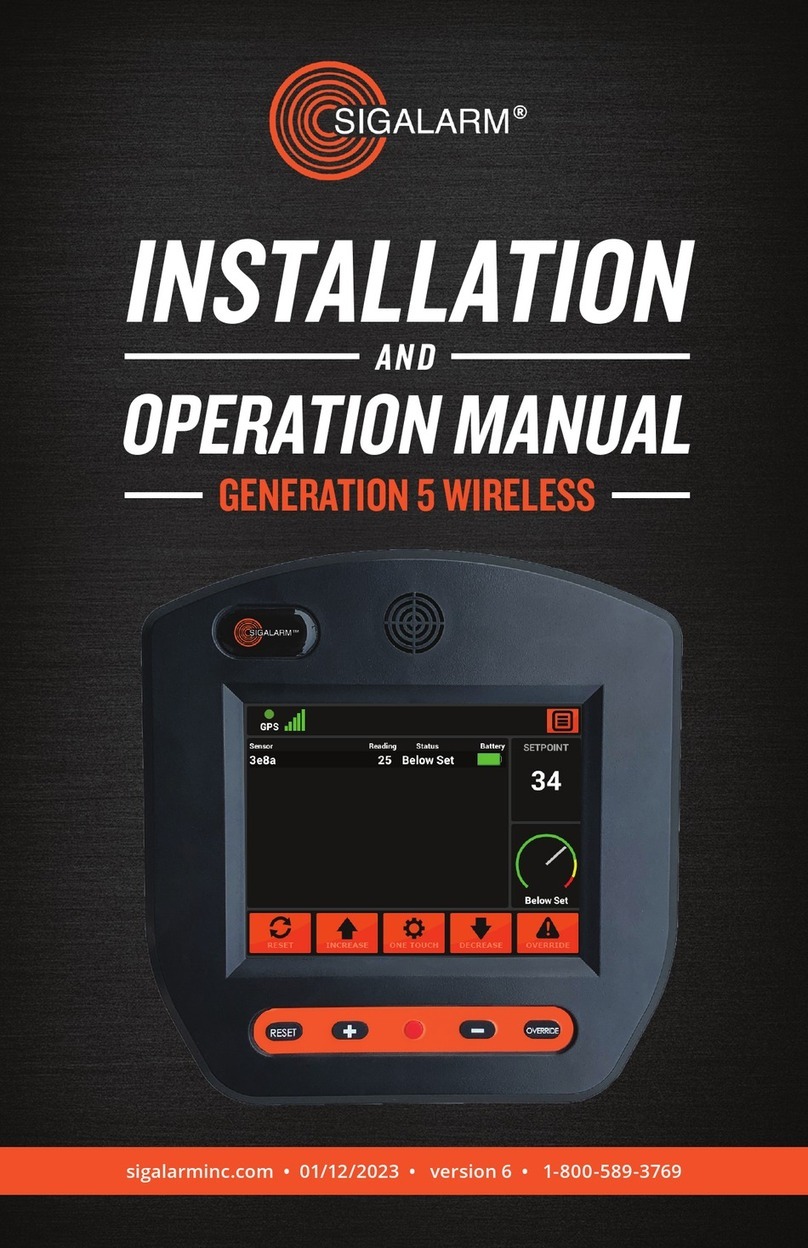
Sigalarm WCM4.0 User manual

SIGALARM INSTALLATION AND OPERATION MANUAL / GENERATION 4 WIRELESS
sigalarminc.com • 08/24/2018 • 1-800-589-3769
INSTALLATION
AND
OPERATION MANUAL
GENERATION 4 WIRELESS


PAY
WITH
PURCHASE ORDER
•••
NOW AVAILABLE AT
SIGALARMINC.COM/SHOP

SIGALARM INSTALLATION AND OPERATION MANUAL / GENERATION 4 WIRELESS
4
1. OVERVIEW....................................................5
1.1 Understanding E Field Detection ............5
1.2 Safety Regulations ....................................5
1.3 Safety Warnings ........................................5
2. INSTALLATION ...........................................6
2.1 Standard Packing List ...............................6
2.2 Installation Precautions ...........................6
2.3 Installation of the Control Module .........6
2.4 Connecting to a Power Source ................7
2.5 Installation of the Wireless Sensor(s) .....8
2.6 Installation of the Speaker .......................12
2.7 Relay Options .........................................13
2.8 Testing/Troubleshooting
the Installation ........................................14
3.MENU DISPLAY IDENTIFICATION..........15
3.1 Home screen/ Detail Overview ...............15
3.2ToolBar......................................................16
3.3SensorDashboard....................................16
3.4 Set Point Display .......................................16
3.5 Sensor Status Gauge ................................16
3.6 Work Zone Indicator ..............................16
(Coming soon)
3.7TouchScreenIcons...................................17
3.8 Knobs and Buttons ...................................17
3.9ActionsScreenOverview..........................18
3.10Admin ......................................................19
3.11 Display Setting ........................................21
3.12SetupDefaults.........................................21
3.13 Manage Sensors .....................................22
3.14ManageDevice........................................22
Information furnished by Allied Safety Systems Inc. DBA Sigalarm in this document is believed to be accurate.
Allied Safety Systems Inc. makes no warranty, express, statutory and implied or by description, regarding
the information set forth herein. Allied Safety Systems Inc. reserves the right to change specications at
any time and without notice. Allied Safety Systems Inc. products are intended for use in normal commercial
and industrial applications. Applications requiring extended temperature range or unusual environmental
requirements such as military, medical life-support or life sustaining equipment are specically not recom-
mended without additional testing on such application. Allied Safety Systems Inc. reserves the right to make
periodic modications of this product without obligation to notify any person or entity of such revision.
Copying, duplicating, selling, or otherwise distributing any part of this manual without the prior consent of
an authorized representative of Allied Safety Systems Inc. is prohibited.
Copyright 2017 Allied Safety Systems Inc. All rights reserved.
4. GETTING STARTED ..................................23
4.1 Initial Control Module Set Up ................23
5. OPERATIONS ............................................24
5.1 Warnings ..................................................24
5.2 Operating Procedures ............................24
5.3 Adjust the Set Point ................................25
5.4 Remote Control Operations ..................27
(Coming soon)
5.5 System Reset ...........................................27
5.6 Override Feature ....................................27
6. DATA MANAGEMENT ..............................28
6.1 Data logger ..............................................28
6.2 Downloading Data (Coming soon) ........28
6.3 Dashboard (Coming soon) .....................28
7. SPECIFICATIONS .....................................29
7.1 Dimensions .............................................29
7.2 Material ....................................................29
7.3 Power Supply Requirements .................29
7.4 E-eld Detection .....................................29
7.5 Range of Eectiveness ...........................29
7.6 Sensor Battery ........................................29
7.7 Control Module Screen ..........................30
7.8 Temperature Specications ..................30
7.9 Speaker ....................................................30
8. TROUBLE SHOOTING ..............................31
8.1 Control module trouble shooting .........31
8.2 Sensor trouble shooting ........................31
CONTENTS

5
SIGALARM INSTALLATION AND OPERATION MANUAL / GENERATION 4 WIRELESS
!
READ THIS MANUAL
IN ITS ENTIRETY
BEFORE
ATTEMPTING
INSTALLATION
OR
OPERATION

SIGALARM INSTALLATION AND OPERATION MANUAL / GENERATION 4 WIRELESS
6
1.1 UNDERSTANDING E-FIELD DETECTION
The Sigalarm system is a reliable and nely tuned “radio” designed to receive only
one selective source: the detectible E-eld present around all AC high voltage
power lines. The strength of the signal (E-eld) depends on the lines voltage and
the distance from the lines. Simple adjustment of the settings on the Sigalarm
unit will provide accurate and repeatable warnings. After the desired setting is
made, a visual and audible alarm will occur whenever the set point/E-eld reading
is detected.
1.2 SAFETY REGULATIONS
It is the equipment operator’s responsibility to know and follow all OSHA, employer,
utility, and equipment manufacturers’ instructions, rules, and regulations.
1.3 SAFETY WARNINGS
Overhead power lines are a constant danger to anyone working with or near
equipment that can come into contact with these high voltage lines. No warning
system should be used in place of standard safety rules and precautions. No
warning device can absolutely prevent an accident. When properly installed and
operated Sigalarm products will provide reliable and repeatable WARNINGS of the
presence of voltage.
1. OVERVIEW
NOT A DISTANCE MEASURING DEVICE
AC VOLTAGE DETECTION ONLY
Sigalarm products are warning systems and should not be used as distance
measuring devices.
Sigalarm products do NOT detect DC voltage

7
SIGALARM INSTALLATION AND OPERATION MANUAL / GENERATION 4 WIRELESS
2.1 STANDARD PACKING LIST
2.2 INSTALLATION PRECAUTIONS
It is highly recommended that Sigalarm products are installed by a certied
Sigalarm installer or competent person. Prior to use of Sigalarm products, training
should be given to the operator by a certied trainer or competent person. Always
test the installation at a safe distance from high voltage power lines. Use extreme
care and a spotter while testing this equipment.
2.3 INSTALLATION OF THE CONTROL MODULE; SIGALARM WCM4.0
The main component of the Sigalarm system is the control module WCM4.0. It
should be mounted in the immediate vicinity of the operator in plain view, without
obstructing their view of the work area.
Systems with an IP rating will be clearly marked. If your control
module does not have an IP rating displayed, do not assume it
is waterproof.
2. INSTALLATION
Part # QTY Description
WCM4.0 1 Control Module
WS4.0 1-16 Sensor(s)
7315-w 1 Parts Bag
WPASPC-5P 1 Horn
2.0wrly 1 Relay Cable
2.0spk 1 Speaker Cable
2.0pwr 1 Power Cable
727-04 1 Mounting Bracket

SIGALARM INSTALLATION AND OPERATION MANUAL / GENERATION 4 WIRELESS
8
2.4. CONNECTING THE CONTROL MODULE TO A POWER SOURCE
Attach the supplied power cable (2.0pwr) to a 12v to 48v DC power supply. The
2.0pwr cord has a red wire, black wire, and a white wire. It can be installed one of
two ways.
SWITCH POWER (Recommended)
Red (Pin 1) Positive -always on 12-48v DC
White (Pin 2) Switched power
Black (Pin 3) Negative -ground
POWER
Red (Pin 1) Positive - always on 12-48v DC
White (Pin 2) Twist together with Red
Black (Pin 3) Negative - ground
Front view of 2.0-pwr
1 2
3

9
SIGALARM INSTALLATION AND OPERATION MANUAL / GENERATION 4 WIRELESS
2.5 INSTALLATION OF THE SENSOR(S); SIGALARM WS4.0
The solar sensors are the component of the system that detects voltage.
TURN THE SENSOR ON:
Remove the sensor lid and put the switch (sw1) in the on position. Prior to operation
connect the solar panel in the lid to the (J3) connector in the base of the sensor.
Close the sensor insuring the solar panel cables are not caught between the seal.
Loosely assemble screws in the sequence shown below
Tighten all screws to an 8 inch-pound torque. There may appear to be a gap
between the lid and the base. This is normal. Over-tightening of screws to close the
gap is not recommended.
1
4 2
3
60 HZ OR 50 HZ
Sensors are shipped with a factory setting to detect 60Hz. Upon request
50Hz presets can be made prior to shipping. Customer may also switch
between 60 Hz to 50 Hz by utilizing the switch (sw2) on the sensor.

SIGALARM INSTALLATION AND OPERATION MANUAL / GENERATION 4 WIRELESS
10
VERIFY PAIRING:
Before permanently installing the sensor and after power is applied to the main
control module verify that the correct quantity of sensors are paired. (Refer to
section 3.13 Manage Sensors for further pairing instruction). Verify the correct
serial numbers are listed in the active sensor column.
PLACEMENT AND INSTALLATION:
The almost unlimited types sizes and congurations of equipment on which
Sigalarm products can be used make it impossible to cover every potential
installation conguration in the manual. However, the following explanation
should help you understand general sensor placement considerations.
Place a single sensor at the highest point of the equipment with the best line of
sight. Where equipment has varying points that can be higher at any given time
multiple sensors should be installed at each of those points. Sensors cannot
be obstructed by metal at any time. The sensors have an adjustable protection
zone, set by the operator on the main control module. Always install sensors with
protection zones overlapping. Please refer to the following suggested installation
diagrams for examples. Wireless Sigalarm systems are not appropriate for all types
of equipment or every jobsite. When in doubt consult a Sigalarm technician
MINIMUM APPROACH DISTANCE – MAD CONSIDERATIONS:
When installing multiple sensors on a piece of equipment, spacing between
sensors should be relative to minimum approach distance or MAD. The distance
between two sensors must not be greater than 1.75 x MAD. This ensures there
are no gaps in protection along the entire length of the boom. For example, if a
minimum approach distance is 20 feet, then the spacing between sensors should
be no more than 35 feet.
Wireless Sigalarm systems are not appropriate for all types of equipment or
every jobsite. When in doubt consult a Sigalarm technician.
NOT FOR ALL TYPES OF EQUIPMENT

11
SIGALARM INSTALLATION AND OPERATION MANUAL / GENERATION 4 WIRELESS
Distance between
sensors cannot
exceed 1.75 x MAD MAD
SENSOR PLACEMENT
The distance between two sensors must not be greater than 1.75 x MAD.
MINIMUM APPROACH DISTANCE - MAD EXAMPLE
If MAD = 20’ Then 1.75 x 20’ = 35’ Distance between sensors < 35’

SIGALARM INSTALLATION AND OPERATION MANUAL / GENERATION 4 WIRELESS
12
PLACEMENT SUGGESTIONS
SAMPLE SENSOR PLACEMENT
The following images are meant for a visual aid only. They are in no way real
life representations actual or implied. You must not rely on the information
in this diagram as an alternative to advice from an appropriately qualied
technician. If you have questions about any installation matter you should
consult an appropriately qualied professional.

13
SIGALARM INSTALLATION AND OPERATION MANUAL / GENERATION 4 WIRELESS
MOUNT THE SENSOR WITH OPTIMUM RADIO POSITIONING
The sensor radio should be placed with the best possible line of sight to the
control module. For example, rotating the sensor so the radio is on the left verses
the right could improve communication with the main control module under
certain circumstances.
Sensor radio
2.6 INSTALLATION OF THE SPEAKER; WPASPC-5P
An exterior weather proof speaker is provided with each system to warn persons
outside the equipment of danger. Place the speaker where it can easily be heard
by ground crew, but will not be damaged during equipment operation. Remove
the plug from the speaker by cutting it to expose the blunt wire. Connect the
blunt speaker wires to the supplied speaker cable (2.0spk) as follows: pin1 (white)
to white, and pin4 (red) to black. Connect the speaker cable to the speaker socket
located on the rear of the control module.
RADIO DISTANCE RATING
Zigbee radio communication is rated for up to 27 meters. Wireless
sensors should not be placed at a distance great than 27 meters from
the control module. Communication between Zigbee radios is aected by
many things. Always test your installation for eective communication in
multiple congurations where applicable.

SIGALARM INSTALLATION AND OPERATION MANUAL / GENERATION 4 WIRELESS
14
2.7 RELAY OPTIONS
Your Sigalarm has four relay ports that allow you to customize your installation.
These relays will open and close under dierent circumstances. A normal
operation, warning, or danger status will open or close these relays according
to the diagram. These relay outputs are for up to a maximum of 50Vdc/75Vac
only. A relay cable will be provided for you with every Sigalarm system. Each
cable has three conductors and pins. The cable can be used in relay ports 1, 2,
3 and 4. Additional relay cables can be purchased for multiple congurations.
Some common relay usage examples include:
▶Wiring the Sigalarm system to your vehicles hydraulics to stop hydraulic
operation (movement) while the system is in an “alarm/danger” state
▶Wiring the Sigalarm systems to an external light that remains lit in a
“Normal operation” (below setpoint) state

15
SIGALARM INSTALLATION AND OPERATION MANUAL / GENERATION 4 WIRELESS
Relay Port 3 & 4 Sigalarm Status
POWER OFF
NORMAL
OPERATION
WARNING
DANGER
Front view of control
module ports
Relay Port 1 & 2
1 2
3
1 2
3
123
123
1 2 3 1 2 3
1 2 31 2 3
1 2 3
1 2 3
RELAY INSTALLATION EXAMPLE
Auto shut down: To stop hydraulics moving when a danger state occurs
connect the supplied relay cable (2.0wrly) to relay port 3 on the rear of the
control module. The blunt end of the (2.0wrly) cable should be wired to
the equipment’s hydraulics using Pin 1(red) and 2(black) so the circuit is
interrupted and hydraulic movement is stopped in a danger status.
*Auto shut down in never recommend for equipment moving a load*
Use the relay diagram to customize the installation to your needs.
SIGALARM RELAY STATUS DIAGRAM
SIGALARM
STATUS DEFINITION OF STATUS RELAY 3 RELAY 4 RELAY 1 RELAY 2
PINS
1 & 2
PINS
1 & 3
PINS
1 & 2
PINS
1 & 3
PINS
1 & 2
PINS
1 & 3
PINS
1 & 2
PINS
1 & 3
power o no power supplied
to control module open closed open closed open closed open closed
normal
operation
sensor status below
set point value closed open closed open open closed open closed
warning approaching
setpoint value
closed open closed open closed open closed open
danger at or above
setpoint value open closed open closed closed open closed open

SIGALARM INSTALLATION AND OPERATION MANUAL / GENERATION 4 WIRELESS
16
▶Applypowertotheunitand verify
the LCD screen turns on and
the unit goes into a maximum
status. If no sensors are bonded
“no data” will appear.
▶Select the reset button and verify
the control module reverts from
max to the last displayed set
point. The set point auto saves
every 10 seconds.
▶Verify the correct quantities of
sensors installed are showing in
the home screen/ detail view, as
well as the active sensor column
of the manage sensors screen
▶Using the decrease icon or -
button lower the set point to
initiate a warning status. Verify
that the external and internal
speakers alarm. Also check that
visual warnings on the control
module are functioning.
▶If relay options are being
utilized verify they are
functioning properly.
▶Using the decrease icon or the -
button, lower the set point further
to initiate a danger status.
▶Verify that the external and
internal speakers alarm. Also
check that visual warnings on the
control module are functioning.
▶If relay options are being
utilized verify they are
functioning properly.
▶Depress the override icon and
adjust the setpoint back to the
desired level.
Verify your installation is correct, and complete the operation
set up prior to operating equipment near power lines.
2.8 TESTING THE INSTALLATION

17
SIGALARM INSTALLATION AND OPERATION MANUAL / GENERATION 4 WIRELESS
3.1 HOME SCREEN / DETAIL VIEW
The home screen or detail view provides the central point of access for
all the systems range of applications. It consists of the following sections:
HOME SCREEN / GAUGE VIEW
HINT
*
3. MENU DISPLAY IDENTIFICATION
▶Tool bar
▶Sensor dashboard
▶Set point display
▶Sensor status gauge
▶Touch screen button icons
You can drag the default home screen
to the left for an alternate gauge view

SIGALARM INSTALLATION AND OPERATION MANUAL / GENERATION 4 WIRELESS
18
3.2 TOOL BAR
3.3 SENSOR DASHBOARD
3.4 SET POINT DISPLAY
3.5 SENSOR STATUS GAUGE
Item Top Tool Bar Function
12 GPS Indicates if the Sigalarm system is receiving GPS service
13 GSM Indicates GSM signal strength; Optional
14 Compass Indicates direction
15 AZ/EI Indicates position
1Menu This icon opens the actions screen
Item Sensor Dashboard Function
11 Sensor EID Displays paired sensors
16 Sensor reading This is a numerical representation relative to the voltage
detected
17 Alert status Indicates the status of the sensor in relation to the set point
4 Battery life Indicates battery status for each sensor
Item Sensor Dashboard Function
2 Set Point The adjustable numerical value at which the operator
gets a danger status. Set point values range from
5-120
Item Status Gauge Function
3 Status Gauge This gauge is a visual representation of sensors read-
ings in relation to the set point
SET POINT DISTANCE CORRELATION
The higher the numerical value of the set point the closer you can get to a
power line. Example: A set Point of 90 will allow an operator to get closer to
a power line than a set point of 20

19
SIGALARM INSTALLATION AND OPERATION MANUAL / GENERATION 4 WIRELESS
3.6 TOUCH SCREEN ICONS
3.7 BUTTONS AND KNOBS
Item Tool Bar Function
5Override The override icon can be selected in a danger state. This
will put the unit in a warning state for 15 second count
down to allow the operator to move away from danger
*This is especially important when the auto shutdown
feature is utilized*
6Decrease Decreases the set point
7One touch Matches the set point to the current highest sensor
reading plus ve
8Increase Increases the set point
9Reset After power is applied reverts unit to last setpoint
Item Button/knobs Function
8a + Increase set point
6a - Decrease set point
10 Enter N/A
9a Reset • After power is applied reverts unit to last set point.
• Depressing the reset button for 15 seconds will reboot
the system, known as a hard reset.

SIGALARM INSTALLATION AND OPERATION MANUAL / GENERATION 4 WIRELESS
20
3.8 ACTIONS SCREEN OVERVIEW
The actions screen provides the point of access for all the following pages:
▶Admin
▶Display settings
▶Setup defaults
▶Manage sensors
▶Manage devices
▶Volume adjustment
Table of contents
Other Sigalarm Control Unit manuals
Popular Control Unit manuals by other brands

Cisco
Cisco PA-VXA Series Installation and configuration

OmarLift
OmarLift HEVOS HE650 operating instructions

HIMA
HIMA HIMax X-DO 12 51 manual

Elko
Elko iNels RFATV-2 quick start guide

Bardiani Valvole
Bardiani Valvole BBZK Instruction, use and maintenance manual

National Instruments
National Instruments NI 9474 Getting started guide

Kauber
Kauber TRIGGER 12V RF user manual

Omron
Omron NX Series manual

DALCNET
DALCNET DLM Series Device manual

XTREME TECHNOLOGIES
XTREME TECHNOLOGIES X-BT-01 quick start guide

Fenwal Controls
Fenwal Controls 05-50 Series manual

CALEFFI
CALEFFI 5335 Series Installation, commissioning and servicing instructions