Smart Storm USI HYDROCELL 4 User manual

Hydrocell 4-8 Toradex USER MANUAL v1.01 TEST page 1 of 38
Contents
Specifications.............................................................................................................2
1. General Information.............................................................................................3
Wiring and Handling Precautions......................................................................................4
2. Introduction..........................................................................................................6
3. Installing the Hydrocell.........................................................................................6
3.1. Location.......................................................................................................................6
3.2. Electrical Connections.................................................................................................6
4. Hydrocell Run Screens........................................................................................8
4.1. Home Screen. ..............................................................................................................8
START/STOP Button........................................................................................10
SPOT SAMPLE Button.....................................................................................12
Emptying the Bottle...........................................................................................13
Temperature Trend Graph..................................................................................16
LEDs..................................................................................................................17
SETTINGS.........................................................................................................17
5. Configuring the Hydrocell. .................................................................................20
5.1. Menu Screen..............................................................................................................21
5.2. Sampling Screen........................................................................................................21
Choosing the Sample Size. ................................................................................22
Entering the Sample and Purge Times...............................................................22
Reset Pump Tube...............................................................................................23
Sampling Mode..................................................................................................23
5.3. Change Over Screen..................................................................................................24
Bottle Status.......................................................................................................25
Programming Modes..........................................................................................26
5.4. Temperature Menu....................................................................................................33
5.5. About Screen.............................................................................................................35
Site Information.................................................................................................35
Change User Password. .....................................................................................35
Set Time and Date..............................................................................................36
6. Wastewater Refrigerated Sampler Service Tasks. ............................................37

Hydrocell 4-8 Toradex USER MANUAL v1.01 TEST page 2 of 38
Specifications
USER INTERFACE
Display
7 inch (800x480 pixels) full colour graphical display with anti-glare cover
Programming
Touch screen (optional wireless keypad)
Operating Systems
Windows CE 60 R3 (license included)
Enclosure rating
IP65
Logging
2GB SD Card records sampling events; alarm conditions; pump starts, pumped
volume and configuration.
SOFTWARE
Modes
Fully user programmable for calibration volume, line purge, start bottle, bottle
sequence’ continues or fixed cycle sample interval, refrigeration temperature.
Display Features
Graphical display of bottle filling action, current fill status, alarm conditions, spot
sampling
Engineering
Password protected engineering mode for diagnostics, testing and software
upgrades.
POWER
Supply (AC)
85-240V 315A
Supply (DC)
24V 12A
PUMP
Media source suitability
Wastewater from non-pressurised submersed sampling point
Type
Peristaltic with 24Vdc motor
Pump tube
Thick walled marprene tube, 8mm internal diameter
Intake tube
Braided LDPE up to 40m length
Maximum lift
7 metres (23 feet)
Repeatability
Typically, ±5ml (this may vary depending on the density of the liquid)
CONTROL
Sample trigger
Pulsed input / 4-20mA input / contact closure / timed
Time based
Fully user programmable
OUTPUTS AND COMMUNICATIONS
Alarms
2 x User programmable SPCO rated at 5A@230Vac
Digital
2 x USB, 1 x Ethernet
Table 1.1 –Device Specifications
Hydrocell 4-8 Toradex USER MANUAL v1.01 TEST page 3 of 38
1. General Information
The information contained in this manual has been carefully checked and is believed
to be accurate. However, Smart Storm assumes no responsibility for any inaccuracies
that may be contained in this manual. In no event will the Smart Storm be liable for
direct, indirect, special, incidental or consequential damages resulting from any defect
or omission in this manual, even if advised of the possibility of such damages. In the
interest of continued product development, Smart Storm reserves the right to make
improvements in this manual and the products it describes at any time, without notice
or obligation. Revised editions may be found on the Smart Storm’s web site
www.smartstorm.eu
•Safety information
Please read this entire manual before unpacking, setting up or operating this
equipment. Pay attention to all danger, warning and caution statements. Failure to do
so could result in serious injury to the operator or damage to the equipment. Make
sure that the protection provided by this equipment is not impaired, do not use or install
this equipment in any manner other than that specified in this manual.
DANGER
Smart Storm products are designed for outdoor use are provided with a high level of ingress protection against liquids and
dust (see specification for rating). If these products are connected to a mains electricity socket by means of a cable and
plug rather than by fixed wiring, the level of ingress protection of the plug and socket connection against liquids and dust
is considerably lower. It is the responsibility of the operator to protect the plug and socket connection in such a manner
that the connection has an adequate level of ingress protection against liquids and dust and complies with the local safety
regulations. When the instrument is used outdoors, it should be connected only to a suitable socket with at least IP44
rating (protection against water sprayed from all directions).
Hydrocell 4-8 Toradex USER MANUAL v1.01 TEST page 4 of 38
•Use of hazard information
DANGER
Indicates a potentially or imminently hazardous situation which, if not avoided, could result in death
or serious injury.
WARNING
Indicates a potentially or imminently hazardous situation which, if not avoided, could result in death
or serious injury.
CAUTION
Indicates a potentially hazardous situation that may result in minor or moderate injury.
NOTICE
Indicates a situation that, if not avoided, could result in damage to the instrument. It also indicates
information that requires special notice.
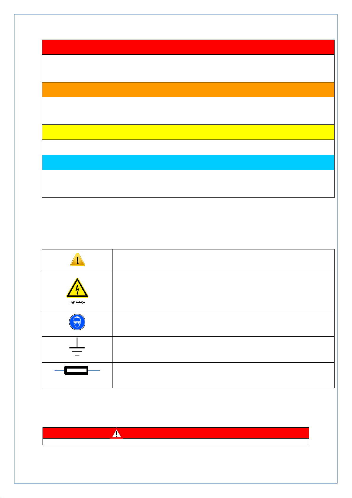
•Precautionary labels
Read all labels and tags attached to the instrument. Personal injury or damage to the instrument could occur if not
fully observed.
This symbol, if noted on the instrument, references the instruction manual
for operation and/or safety information.
This symbol, when noted on a product enclosure or barrier, indicates that a
risk of electrical shock and/or electrocution exists
This symbol, if noted on the product, indicates the need for protective eye
wear.
This symbol, when noted on the product, identifies the location of the
connection for Protective Earth (ground).
This symbol, when noted on the product, identifies the location of a fuse or
current limiting device.
Wiring and Handling Precautions
DANGER

Hydrocell 4-8 Toradex USER MANUAL v1.01 TEST page 5 of 38
Electrocution Hazard. Always disconnect mains supply before removing covers and
connecting any external wiring.
Only qualified Electricians should install this product. IET BS7671:2008 wiring
regulations must be adhered to when installing the product.
NOTICE
Delicate internal electronic components can be damaged by static electricity,
resulting in indeterminate instrument performance or eventual failure. Smart Storm
recommends taking the following steps to prevent ESD damage to your instrument:
•Before touching any instrument electronic components (such as printed
circuit cards and the components on them) discharge static electricity from
your body. The user can accomplish this by touching an earth - grounded
metal surface for 3 seconds such as the chassis of an instrument, or a metal
conduit or pipe.
•To reduce static build-up, avoid excessive movement. Transport static-
sensitive components in anti-static containers or packaging.
•To discharge static electricity from your body and keep it discharged, wear a
wrist strap connected by a wire to earth ground, especially when handling
circuit boards.
•Handle all static - sensitive components in a static - safe area. If possible,
use anti-static floor pads and work bench pads.
DANGER
Electrocution hazard. Always install a ground fault interrupt circuit (GFIC)/ residual
current circuit breaker (RCCB) with a maximum trigger current of 30 mA. If installed
outside, provide overvoltage protection through a MCB rated not greater than 5
Amps.
DANGER
With fixed wiring, a disconnecting device (local interruption) must be integrated into
the power supply line. The disconnecting device must meet BS7671:2008 standards
and regulations. It must be installed near the device, be able to be reached easily
by the operator and labelled as a disconnecting device.
If the connection is established using a mains connection cable that is permanently
connected to the power supply, the plug of the mains connection cable can serve
as local interruption.
DANGER
Ensure the relays are not subjected to loads great than 5 Amps as this will cause
internal damage and possible product destruction.

Hydrocell 4-8 Toradex USER MANUAL v1.01 TEST page 6 of 38
2. Introduction.
The Hydrocell Wastewater Sampler Range is designed to collect composite (flow, event or
time proportional) samples of trade effluent discharges in industrial applications.
The 2/4/8 bottles available for sampling in the Hydrocell gives flexibility in sampling and
collecting, allowing both Continuous and Single Programmed Sequences to be performed.
The Hydrocell 4 & 8 incorporates a refrigerated compartment to keep the samples cool and
help maintain the integrity of the effluent. The Thermo-electric cooler is also used for frost
protection to heat the samples if the temperature falls below 0ºC.
The large display and touch screen provide simple, user friendly programming and clear
reporting of the Sampler Status.
This Instruction manuals show screen shots for the 8-bottle sample for illustrative
purposes. The 2 &4 bottle samplers differ only in the number of the bottles shown on the
screen and all functionality (apart from the cooler) is the same on all 3 models.
3. Installing the Hydrocell.
3.1. Location.
The Hydrocell 8 is IP65 rated allowing it to be located outside and close to the required sample
point. Whilst it includes a High-Resolution Display, care should be taken when positioning the
Hydrocell to avoid direct sunlight. This will make the screen difficult to see and ultimately
cause permanent damage.
3.2. Electrical Connections.
The Hydrocell can be supplied in either 24Vdc or 85-240Vac versions and is supplied with a
pre-fitted 5-meter power cable:
24V version - Cable 1 +ve, Cable 2 -ve/GND
AC version –Cable 1/Brown Live, Cable 2/Blue Neutral, Green and Yellow GND.
The sampler will boot immediately the power is connected; it is recommended a local
switch/isolator is fitted to the power cable.
A 5-meter sample request cable with a 3-pin connector is supplied. This mates with the
connector on the side of the Hydrocell.

Hydrocell 4-8 Toradex USER MANUAL v1.01 TEST page 7 of 38
Intake Hose Connection
The Hydrocell is supplied with a 10-meter length of braided intake hose. One end should be
attached to the Peristaltic Pump and secured with a Jubilee Clip.
The other end should be placed in the effluent at the point from which the sample is to be taken.
The following points should be considered when fitting the intake tube:
•Keep the run as short as possible.
•Avoid U bends in the hose as this can lead to airlocks and inaccurate sample volumes.
Ideally, place the Hydrocell as high as possible such that the intake tube runs down and
horizontally.
•Ensure that the intake tube is below water level when a sample is requested –where a
low flow in anticipated, it may be necessary to fit a reservoir to collect the liquid (e.g.
after a flume).
•It may be advisable to fit a weight to the end of the Hose or to fit a solid pipe to ensure
there is no bending of the Hose above the waterline.
•During a purge and sample the effluent may be disturbed and cause incorrect flow
readings. If possible, place away from any open channel measuring equipment.
•Ensure the sample taken is representative of the effluent going to drain. Some systems
can be prone to acidic or caustic build up near the edge of tanks and flumes.
•Ensure the sample intake is clear of any build-up of sediment.
•Consider fitting a filter to the end of the Intake Hose to stop the Hose becoming blocked.

Hydrocell 4-8 Toradex USER MANUAL v1.01 TEST page 8 of 38
4. Hydrocell Run Screens.
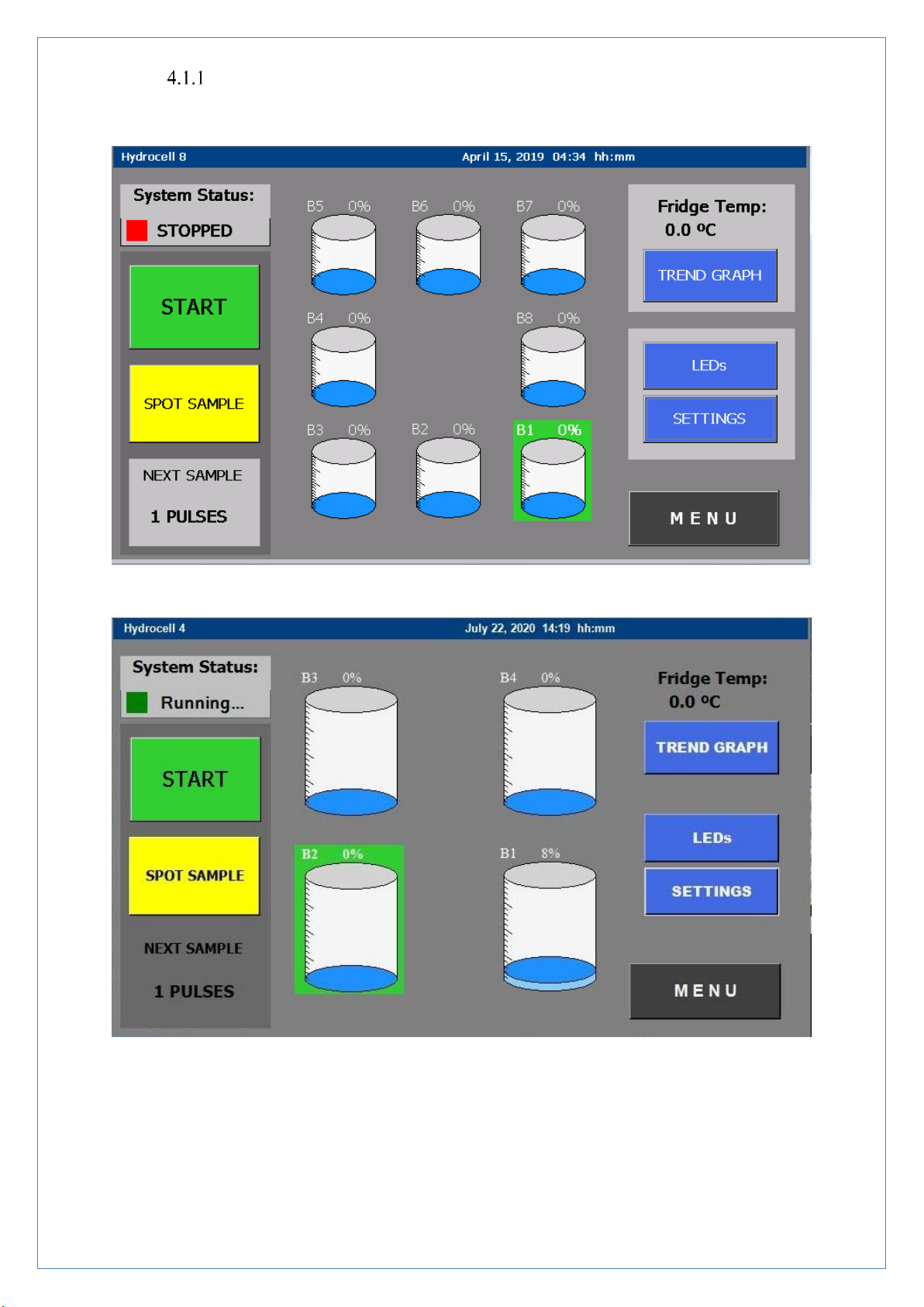
4.1. Home Screen.
Figure 5.1 HC 8 Home Screen.
Figure 5.1.1 HC 4 Home Screen
The Home Screen provides information about the current status of the Hydrocell. Each of the
bottles is shown on the Screen along with the percentage the bottle of effluent in the bottle.

Hydrocell 4-8 Toradex USER MANUAL v1.01 TEST page 9 of 38
The Active Bottle (Bottle 1 in figure 5.1) is shown with a green outline, and this is the bottle
into which samples are currently being taken. The System Status is displayed at the top left of
the screen immediately above the Stop/Start and Spot Sample Buttons.
An indication of the time/events to the next sample is displayed in the bottom left of the screen.
This may be the number of Pulses/Contact closures, the Time or the volume of Flow, depending
up on the configuration of the Sampling.
On the right of the display the current temperature of the Refrigerated Compartment is shown
and a button to allow the Temperature Trend Graph display screens. The LEDs button opens a
pop-up box to indicate the function of the six LEDs on the USI Fascia and the Settings button
allows access to Screens giving information regarding the Set-Up and History of the Hydrocell.
Finally, a button is provided to access the Menu for configuring the Hydrocell.
The Home Screen is also used to empty Bottles and take Spot Samples.
Hydrocell 4-8 Toradex USER MANUAL v1.01 TEST page 10 of 38
START/STOP Button
Figure 5.2 HC8 Pressing the Stop Button.
Figure 5.2.1 HC4 Pressing the Stop Button
When the Stop Button is pressed the Button will change to a green Start Button and the System
Status will change depending on the Programming Mode of the Hydrocell.

Hydrocell 4-8 Toradex USER MANUAL v1.01 TEST page 11 of 38
If the Hydrocell is in Continuous Mode, the System Status will show STOP and the Active
Bottle will remain unchanged until the Hydrocell is restarted and a Bottle Changeover Time is
reached.
If the Hydrocell is in Programmed Mode, the System Status will show PAUSE and the Active
Bottle will change when a Bottle Changeover Time is reached in order to remain synchronised
with the program.
In both Modes no samples will be taken whilst the Hydrocell is either STOPPED or PAUSED.

Hydrocell 4-8 Toradex USER MANUAL v1.01 TEST page 12 of 38
SPOT SAMPLE Button.
The Spot Sample Button is used to take a Manual Sample. This is typically used to check the
operation of the sampler (calibration and functionality) or to take an immediate, non-composite
sample for testing.
Figure 5.2 HC8 Spot Sample.
Figure 5.2.1 HC4 Spot Sample.

Hydrocell 4-8 Toradex USER MANUAL v1.01 TEST page 13 of 38
When the SPOT SAMPLE Button is pressed, the Button changes to a red STOP Button.
Pressing this Button at any time during the Sample Process will immediately halt the process
and return the sampler to its previous status.
The Spot Sample will mirror the process when a sample request is received, having the same
timings and sequence and sampling into the Active Bottle.
Following the SPOT SAMPLE request there will be a delay whilst the Hydrocell selects the
Active Bottle. The System Status will then change to Purging and the Peristaltic Pump will
rotate in the direction that will drive air out through the Intake Hose (if the pump is functioning
correctly this will cause bubbling in the effluent). The number of Purges is set on the Sampling
Page.
The System Status will then change to Sampling and the Peristaltic Pump will rotate in the
opposite direction. This will draw a sample up through the Intake Hose and into the Active
Bottle.
Finally, the Hydrocell will carry out a number of Post Purges designed to evacuate the INTAKE
HOSE of any liquid.
At the end of the Spot Sample Sequence the Hydrocell will return to its previous Status and the
percentage volume in the Bottle will increase by the volume set on the Sampling Page.
N.B. The Spot Sample will take a Sample even when the Status is STOPPED. Care must
be taken that it is not pressed when the Peristaltic Pump is being worked upon.
Emptying the Bottle.
The Hydrocell tracksthe volume of liquid in each Bottle by multiplying the number of Samples
taken into the Bottle by the Sample size. This volume is then shown as a percentage of the total
Bottle volume.
If the next Sample would make the Bottle exceed 95% of its volume, the Sample will not be
taken and a pop-up message will appear on the Display.


Hydrocell 4-8 Toradex USER MANUAL v1.01 TEST page 15 of 38
To empty the Bottle, select the Bottle to be emptied using the Touchscreen, the EMPTY Button
will appear in the centre of the Display.
Figure 5.4 HC8 Emptying the Bottle.
Figure 5.4 HC4 Emptying the Bottle
Press the EMPTY Button and the volume will be reset to 0% and the Hydrocell will now take
a Sample into that Bottle.

Hydrocell 4-8 Toradex USER MANUAL v1.01 TEST page 16 of 38
N.B. Emptying the Bottle only resets the volume of the Bottle it does not physically empty
the Bottle!
After resetting the volume, it is essential that all the effluent is removed from the Bottle
to prevent overfilling.
When the Hydrocell is running in Continuous Mode an option is provided to Pause the program
if the Active Bottle has not emptied since it was last filled. This is to maintain the integrity of
the sample to a single changeover time. It is therefore essential to ensure the Bottles are
regularly emptied.
Temperature Trend Graph.
The Hydrocell Home Screen shows the current temperature inside the refrigerated
compartment and a Trend Graph to ensure it is functioning correctly.
Figure 5.5 Temperature Trend Graph.
The ON temperature for the Thermo-electric Cooler is shown in red on the right-hand side of
the screen, and the OFF temperature is shown in Blue. The temperature is shown as a bar graph
with a blue line indicating the temperature is below the OFF temperature and a red line
indicating the temperature is above the ON temperature.
If the Refrigerating Unit is functioning correctly the Trend Graph will show a majority of green
lines.
Hydrocell 4-8 Toradex USER MANUAL v1.01 TEST page 17 of 38
The Hydrocell has two Thermistors one at the top and one at the bottom, either of which can
be used to regulate the temperature in the compartment. The Trend Graph for either Thermistor
can be selected by pressing T1 or T2.
Four time scales are selectable, to show the temperature over the last 1, 2, 4 and 8 hours and
the graph can be manually refreshed by pressing the selected time scale.
If the Hydrocell is turned off the information will be lost, and the Trend Graph will restart.
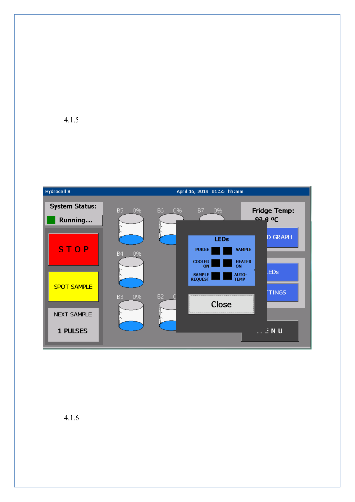
LEDs.
Pressing the LEDs Button on the Home Screen generates a pop-up which identifies the
functionality of the six LEDs on the Hydrocell Fascia.
Figure 5.6 LEDs.
To return to the Home Screen, press the Close Button.
SETTINGS.
The SETTINGS Button gives access to pages showing information regarding the Set-up and
operation of the Hydrocell. The different screens can be accessed using the left and right scroll
buttons at the bottom of the screen.

Hydrocell 4-8 Toradex USER MANUAL v1.01 TEST page 18 of 38
•Sampling Screen
Fig 5.7 Sampling Information.
Shows information on the Sampling and Purge times and Program Mode. These settings are
explained further in the Sampling set-up section.
•Site Information Screen
Fig 5.8 Site Information.
•Bottle Information

Hydrocell 4-8 Toradex USER MANUAL v1.01 TEST page 19 of 38
Fig 5.9 Bottle Information.
The Bottle Information screen shows details of the information programmed in the Change
Over menu.
The right hand side of the screen details the time and date that each of the Bottles became the
Active Bottle, with the current Active Bottle highlighted in green.
The Next Active Bottle and the time it becomes active is indicated on the top left of the screen.
•Cooler and Pump Information.
Fig 5.10 Cooler and Pump Information.
The Cooler Information details the settings in the Temperature Menu, with the addition of the
time the cooler was last switched ON and OFF. Monitoring these values gives an indication of
the performance of the Cooler and Insulation of the Hydrocell.
This manual suits for next models
2
Table of contents
Other Smart Storm Industrial Equipment manuals

Popular Industrial Equipment manuals by other brands


Newlong
Newlong NP-7A instruction manual

SCHUNK
SCHUNK LEG 400 Assembly and operating manual

APPLIED MATERIALS
APPLIED MATERIALS CoolEND 0190-13674 Installation, operation, basic service

schmersal
schmersal AZM300Z-I2-ST-SD2P-T Instructions for operation

Siemens
Siemens 3WN6 quick start guide

WNT
WNT ZSG Installation and operating instructions


