Smart Witness SVC300GPS User manual

SVC300GPS!
3 CAMERA VEHICLE JOURNEY RECORDER!
!!Thank you for purchasing this Journey Recorder.
!!Please ensure that you read and understand this USER GUIDE
and use it before connecting and installing this Recorder.
!!Please store the USER GUIDE in an easily accessible location.
VER 1.0.0 1st Edition
USER GUIDE!


Caution
Damages due to production malfunction, loss of data, or other damages occurring while
using this product shall not be the responsibility of the manufacturer. Although the
product is a device used for recording videos, the product may not save all videos in the
case of a malfunction. In the case of an accident, the sensor may not recognize the
shock when the impact is light and as a result it may not begin recording automatically.
SAFETY ADVICE
CAUTION
RISK OF ELECTRIC SHOCK
DO NOT OPEN
CAUTION: TO REDUCE THE RISK OF ELECTRIC SHOCK,
DO NOT REMOVE COVER.
NO USER-SERVICEABLE PARTS INSIDE.
REFER SERVICING TO QUALIFIED SERVICE PERSONNEL.
WARNING:
TO PREVENT FIRE OR ELECTRIC SHOCK HAZARD, DO NOT EXPOSE
THIS APPLIANCE TO RAIN OR MOISTURE.
Caution
Connect your vehicle’s power cable to the product after starting the vehicle.
The instant over voltage generated when starting up the vehicle may damage the
product if it is already connected.
Caution
Install the product where it does not block driver’s visibility and where there is
no airbag installed. This could cause an accident or might injure passengers in
case of accident
Please make sure you follow the safety advice/instructions given in the user guide.
3
Caution
RISK OF EXPLOSION IF BATTERY IS REPLACED BY AN INCORRECT TYPE.
DISPOSE OF USED BATTERIES ACCORDING TO THE INSTRUCTIONS.
Battery for RTC (Real Time Clock) inside

GPS RECEPTION
1.!Activate the product in an area without large buildings to
improve GPS reception.
2.!The temperature range for optimum operation of the
GPS receiver in your car is -10 ~ 50°C.
1.!When using the product for the first time or after a long
period (more than three days), it may take a little longer
to recognize your current location.
It may take between five and thirty minutes to get GPS reception.
GPS reception may be impaired under the following circumstances
1) If there is an object at the end of the GPS antenna
2) If your vehicle has metallic elements on the windshields
3) If equipment generating electromagnetic waves that interfere with the GPS
signal is installed in the vehicle e.g: Other GPS devices such as a certain
type of wireless activated alarms, MP3 and CD players and camera alarms
using GPS.
4) If you are using a receiver connected by cable, electric interference can be
avoided by simply changing the location of the receiver (antenna).
5) On heavily overcast or cloudy days, if the vehicle is in a covered location
such as under a bridge or raised roadway, in a tunnel, an underground
roadway or parking area, inside a building or surrounded by high-rise
buildings.
6) If GPS signal reception is poor, it may take longer to locate your current
position when the vehicle is moving than when it is stationary.
4
The commercial purpose GPS has the average range error of more
than 15 meters and the range error could be more than 100 meters
due to environmental conditions like buildings, roadside trees etc.
CONTENTS
5
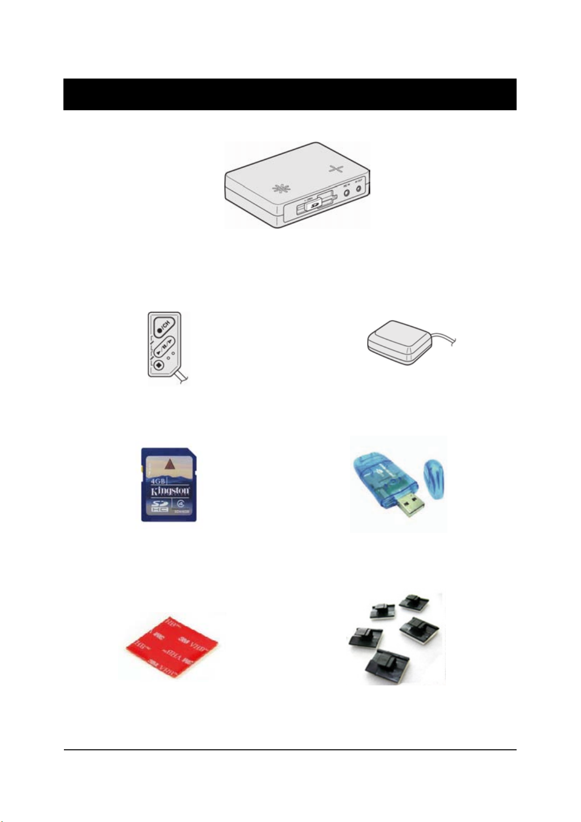
Wire Splice clips (x5)
Sticker for mounting
(double sided 3M tape x1)
Smart Witness SVC300GPS
Receiver & Recording Unit
4GB SD memory card
(Note: Analysis Software is
on this SD card)
USB SD Card Reader
Smart Witness SVC300
GPS Antenna Unit
Remote Controller
6
CONTENTS
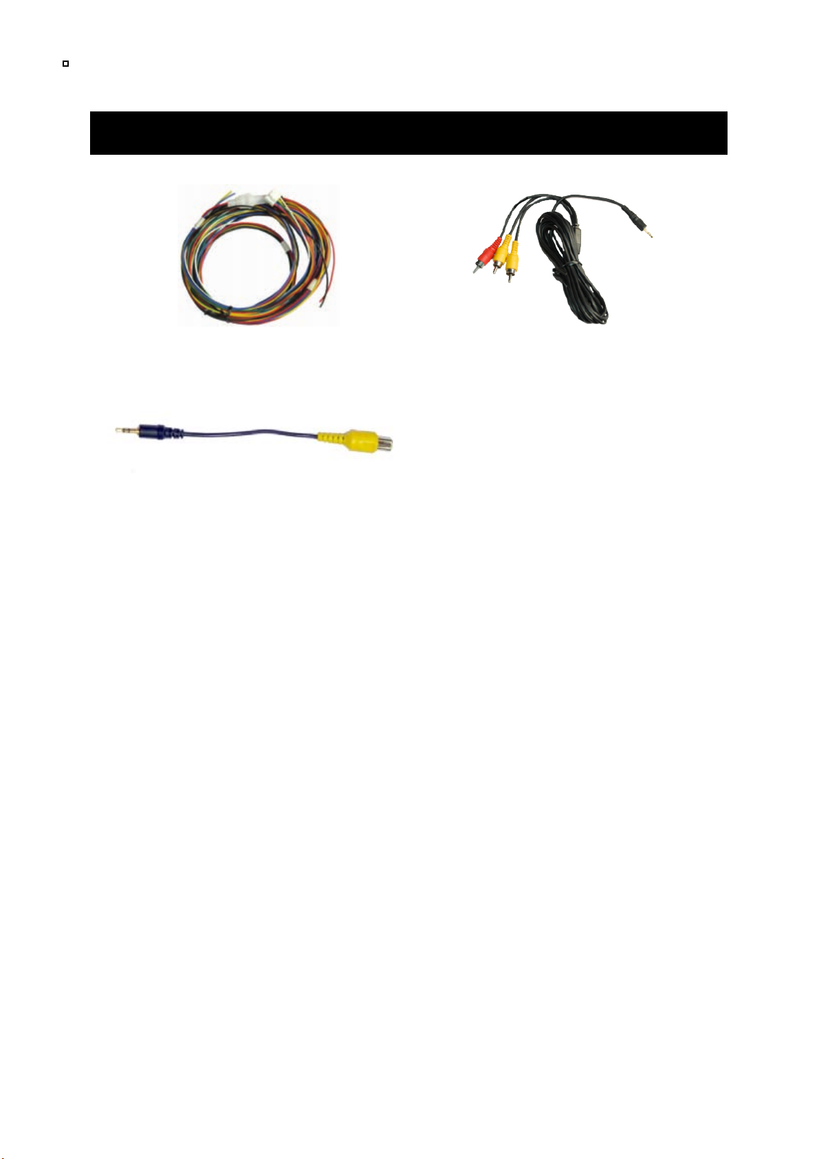
AV Output Cable
Power Cable
2x Camera Input Cable

IDENTIFYING PARTS
SVC300GPS JOURNEY RECORDER
REAR
7
SD Slot
SD Door
AV Output
External MIC
input
Speaker
Internal Microphone
Camera Input 1, 2
Remote Control Input
GPS Input
Power Input & Alarm
(Car Signal) Input
Rear View
Camera Input
FRONT
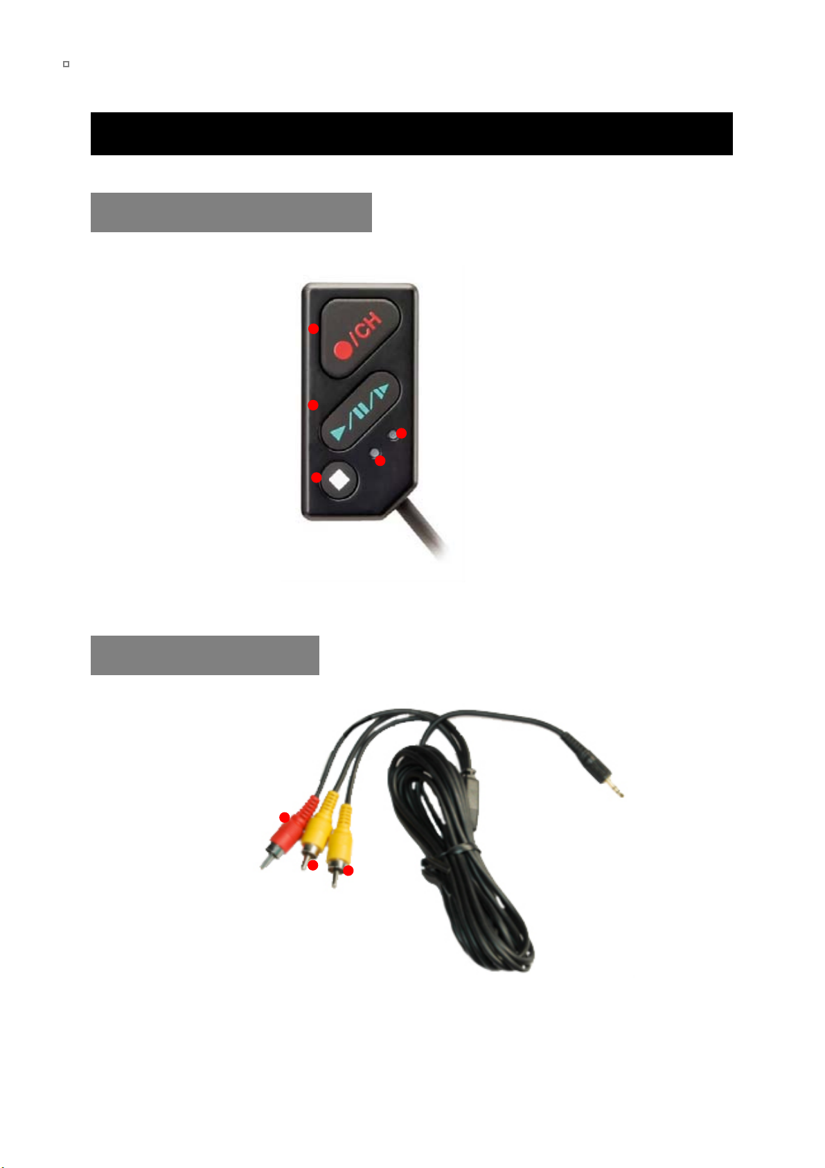
IDENTIFYING PARTS
REMOTE CONTROLLER
8
Record LED
(Blue)
Overwrite LED
(Red)
Snap Shot Button
Play Button
Record Button
AV OUTPUT CABLE
Video
Output 1
Video
Output 2
Audio
Output
9
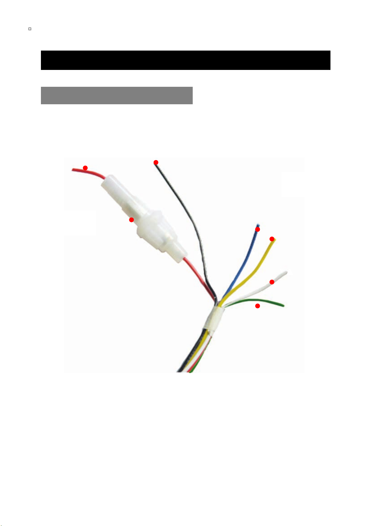
IDENTIFYING PARTS
POWER & CAR SIGNAL INPUT
Fuse
250V 3A
Power (+)
(Red)
Ground
(Black)
Alarm 1
(Blue)
Alarm3
(Yellow)
Alarm 2
(Green)
Car pulse
(speed)
(White)

FUNCTION (MAIN UNIT)
Automatic start
Turn on the vehicle power, SVC300GPS will be automatically started. (Use the
power cable provided).
Event record
The Event recording will be start automatically by the Alarm 1 to 3 or by the
G-Sensor level.
Panic record
The Panic recording can be started by pressing the RECORD button.
Normal record (Continuous record)
The Normal record will be automatically started after power on.
The SVC300GPS will not make a separate event file during the continuous
recording. It will mark the Event area as ‘Alarm1~3’, ‘G-Sensor’ or ‘Record button’
In the continuous recording file which can be easily searched for during playback.
Live screen and Camera3 (Rear View)
SVC300GPS will display the live screen on the monitor.
The camera channel can be changed using the Information OSD.
If camera 3 (Rear View camera) is on, the live display channel will automatically
switch to camera 3. To use camera 3 as an automatic rear view camera then pow
er it from the vehicles reverse lights, when the reverse light comes on the camera
will be displayed on the monitor automatically.
Playback in the car
Recorded files can be played back in the car.
SD Memory Card Format
Remove the power first. Press the SD CARD FORMAT button and hold. Then
connect the power for initialisation. Once complete, all video & log files will be
deleted and the configurations will default to the factory settings.
10
NOTE: The unit will not start recording immediately after the power is turned on.
It takes around 1 minute for the built-in power backup system to charge. Thereafter, the
internal flash memory will be ready to record.
NOTE: PC Viewer software is pre-loaded on the SD card. Please ensure you have
installed the software to your PC before you format the card

Built-in power backup (Super Capacitor)
If power to the unit is interrupted, SVC300GPS creates the last file using the
internal battery.
Blue LED (RECORD)
The Blue LED shows the power is on. It will flash during event recording.
Red LED (WARNING)
The Red LED will turn on when there is video loss or the system has failed.
Buzzer
A ‘Beep’ sound will occur when recording starts (this can be turned off if
required) and to signal a system error.
FUNCTION (MAIN UNIT)
11

OPERATION
Begin Recording
1.!Make sure that the power cable is properly connected and turn on the car
power.
2.!Blue LED & Red LED will turn on and flashing slowly simultaneously and
then the Blue LED will remain on. Blue LED light means SVC300GPS is
now ready for recording.
Removing the SD memory card
Turn off the power and then check the BLUE LED light. Once the BLUE LED
light is off, take out the SD Memory Card .
Inserting the SD memory card
Turn off the power and then check the BLUE LED light. Once the BLUE LED
light is off, insert the SD Memory Card .
System Error Buzzer
A ‘Beep Beep’ sound will occur and the BLUE & RED LED lights will flash
simultaneously when there is a system error or SD card is not inserted.
Check the SD Memory Card when this occurs.
12
NOTE: Recording Modes
•!Normal recording (Continuous recording) will start automatically, (if set with your PC)
•!Event recording will automatically begin when triggered by the G-Sensor and will
begin with one short ‘Beep’ sound.
•!Panic/Manual recording can be started by pressing the RECORD button.

OPERATION
13
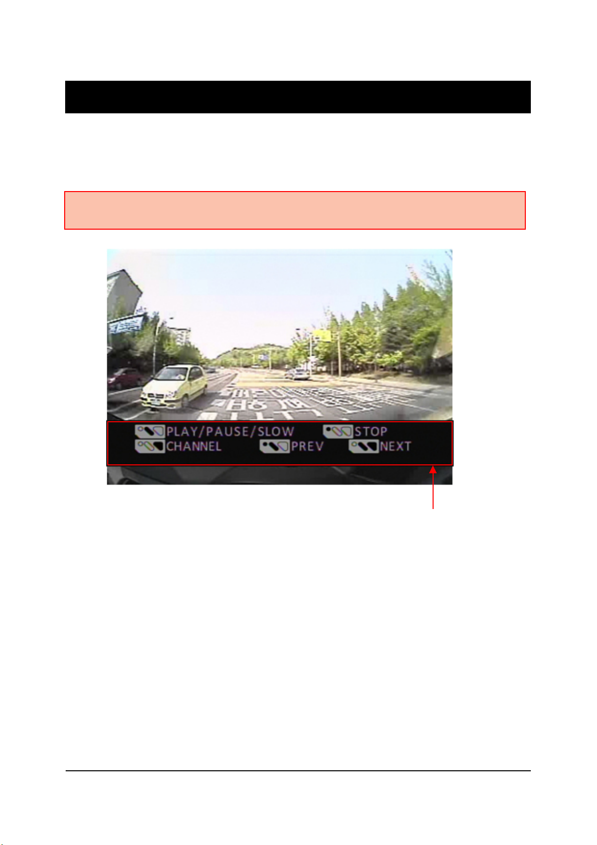
Press the PLAY button and the Information OSD (On Screen Display) will
show up on the monitor as below:
The INFORMATION OSD will be turned off automatically after 30 seconds.
INFORMATION OSD
LIVE VIEW
Turn on the SVC300GPS and press the PLAY button to turn on the Information
OSD (On Screen Display).
To change the live display channel, press the RECORD button to select the
camera then press the STOP button.
If the Camera 3 (Rear View camera) is on, the Live View display camera will
be automatically switched to display Camera 3.
!"#$%
!"#&%
!"#'%
!"#$%&'()
!%
!%
!%
*'"+,()-+(')
!()*)+,%
!()*)+,%
!()*)+,%
./%01&23)-+.,/%
4560%$1%
7$',8,1&'3)23%
!/(1+0%244%
9:6';<+,)='$'03)
50'6%70'6%80'%
9:6';<+,)>%01?,%#+;3)
50'6%70'6%80'%
41,@8%,')A',<1+;3))
-9!'11:;-%
>/,,';&)B1@'3)
$<0$=%%%%&1%2!>%&1$1%

G-Sensor Calibration Unsuccessful.
Press any key.
OPERATION
G-SENSOR CALIBRATION
14
G-Sensor Calibration is needed after installing the SVC300GPS. It detects
the installed direction of the SVC300GPS for it to accurately record the
journey direction.
1.!Press and hold the PLAY & STOP buttons together and then turn on the
power. The G-Sensor Calibration screen will be displayed.
2.!Press and hold the PLAY & STOP buttons together again for more than
2 seconds. The G-Sensor Calibration OSD will show the following:
This G-Sensor Calibration is only needed at the first time the SVC300GPS
is used.
Park vehicle on a flat surface with at le
ast 5 metres of space directly ahead.
Press the Event/Panic Button.
Move car directly forward 5 metres.
G-Sensor Calibration Successful.
Press any key.
RETRY

OPERATION
PANIC RECORD BY RECORD BUTTON
15
Begin recording automatically by pressing the RECORD button. Recording will
start with one short ‘Beep’ sound and the Blue LED will be flash during the
recording.
The SVC300GPS will not make a separate event file during the continuous
recording. It will mark the Event area as ‘Record button’ in the continuous
recording file which can be easily searched for during playback.
SNAP SHOT RECORD BY BUTTON
Press the SNAPSHOT button. The SVC300GPS will take a snapshot of 1
image with 5 seconds of audio with one short ‘Beep’ sound.
OPERATION
PLAYBACK
16
Press and hold the PLAY button for more than 2 seconds. The latest recorded
file will playback on the screen.
Playback Control panel
PLAYBACK CONTROL BUTTON
Channel change: Press the RECORD button.
Move to the previous file: Press and hold the STOP & PLAY button.
Move to the next file: Press and hold the RECORD & PLAY button.
Play/Pause: Press the PLAY button.
Slow Play: Press and hold the PLAY button more than 1 second.
Return to Record Mode: Press and hold the STOP button for more than 2
seconds.
Note: Recording cannot be done during playback. If Event Recording is on, the PLAY
button will not work.
SOFTWARE USER GUIDE
SVC300GPS PC Viewer Guide
17
PC SYSTEM REQUIREMENT
If the PC does not meet the minimum system requirement, the
Analysis Software may not function properly.
OS Windows 2000, Windows XP
Windows Vista, Windows 7
CPU Pentium4 2.6GHz or higher
RAM 512MB or higher
Interface SD Memory Card Reader
HDD
Free space
Install 20MB or higher
Backup 2GB or higher
Display 1,024 x 768 pixel/High Color(16bit) or higher
Recommended PC specifications for PC Viewer software
18
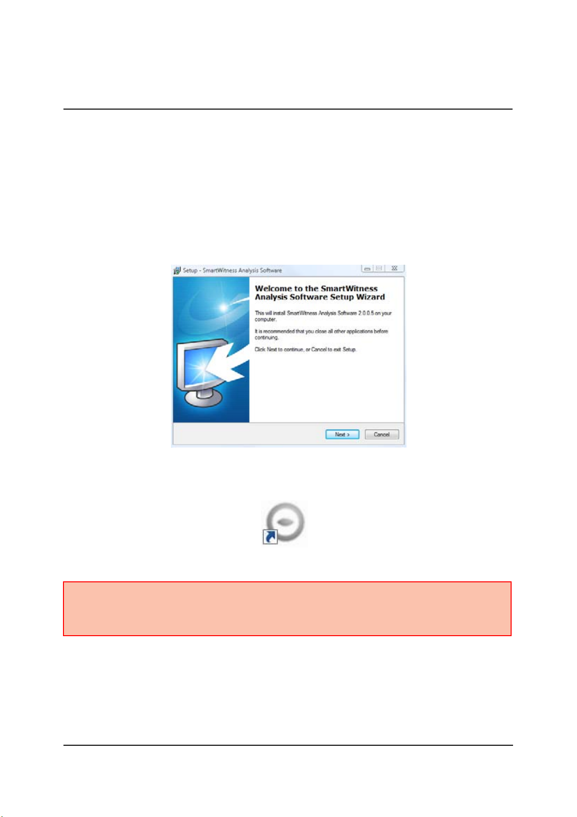
SOFTWARE INSTALLATION
1. Connect the SD card into your PC (if your computer does not have and
SD card slot use the USB SD card reader) and open the “My Computer”
2. Right-click the “DRIVEREC1” drive and select OPEN
3. Double click SETUP.EXE in the ‘pcsw’ folder.
4. Select the language and then follow the dialog box.
5. The “PCViewer” icon will be displayed on your desktop.
NOTE: To Un-install the PC Viewer
Open the ‘Control Panel’.
Select ‘Remove Program’ and remove Smart Witness Analysis Software.
PC Viewer software is on the provided SD card.

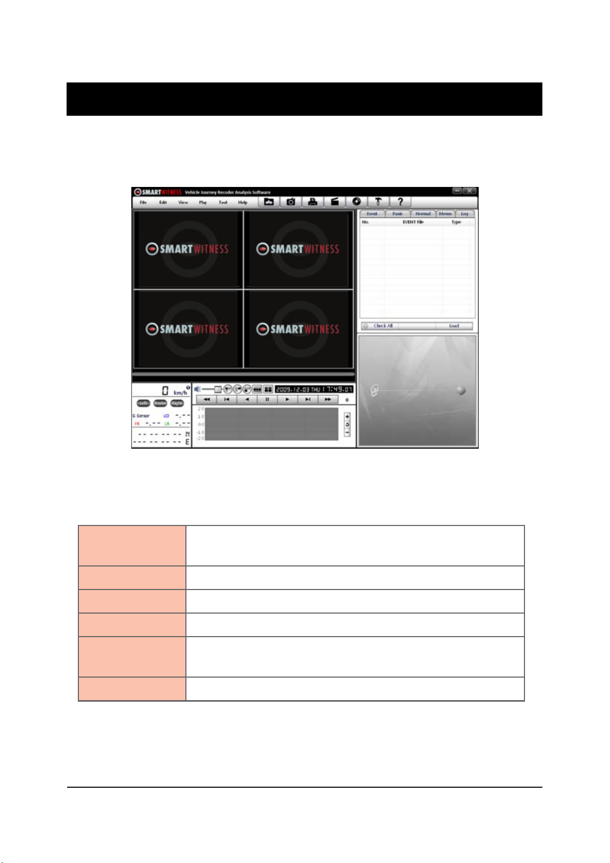
Connect SD memory card
1. Connect SD memory card in to the SD card reader.
2. Run ‘Smart Witness’
3. Select FILE and then click ‘Select Data Folder’ or click the OPEN button
19
[OPEN] button
4. Select SD memory card folder at the folder select window.
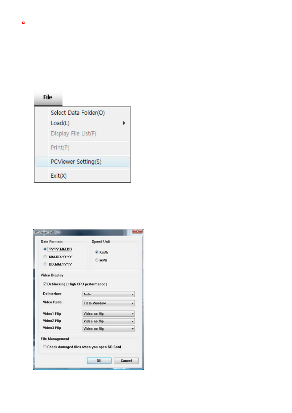
PC VIEWER SETTINGS
20
The ‘date’ formats and ‘speed’ unit will be set automatically according to the PC
Windows setting. However it can be changed with this PC viewer setting menu.
To see the better quality playback picture on your PC, check Deblocking box.
To set PC Viewer select FILE and then click ‘PC Viewer Setting”
This setting is for the PC Viewer software itself.
To set the recorder, refer to page 27.
Table of contents
Other Smart Witness Camcorder manuals


