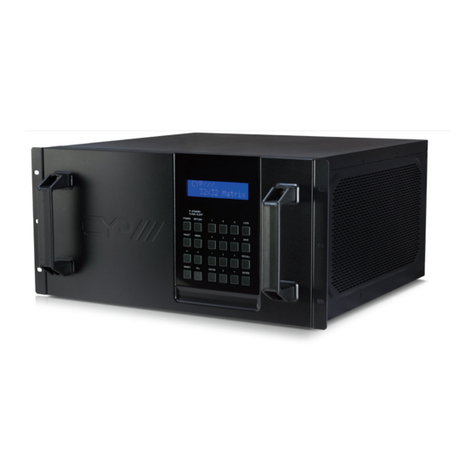
SmartAV MXwall LT V2 P20 Series User manual

USER MANUAL
MXwall LT V2
4-Input and Up to 12-Output Video Wall Processor and Matrix Switch
Designed and Manufactured in the USA
1-800-284-2131
www.smartavi.com

4-Input and Up to 12-Output Video Wall Processor and Matrix Switch 2
OVERVIEW
TECHNICAL SPECIFICATIONS_________________________________________________________________
WHAT’S IN THE BOX?________________________________________________________________________
FRONT AND BACK___________________________________________________________________________
HARDWARE INSTALLATION__________________________________________________________________
AVAILABLE CONFIGURATIONS_______________________________________________________________
FRONT PANEL CONTROL_____________________________________________________________________
SOFTWARE INSTALLATION___________________________________________________________________
USING THE SOFTWARE______________________________________________________________________
CONNECT TO THE NETWORK_______________________________________________________________
SYSTEM ERROR______________________________________________________________________________
USING THE TABLET__________________________________________________________________________
CONFIGURATION FOR 4U AND 2U UNITS____________________________________________________
TROUBLESHOOTING_________________________________________________________________________
TECHNICAL SUPPORT________________________________________________________________________
LIMITED WARRANTY STATEMENT____________________________________________________________
3
4
4
5
6
7
8-11
11-20
20
21
22
23
24
24
25

4-Input and Up to 12-Output Video Wall Processor and Matrix Switch 3
Technical Specifications
VIDEO
Video Amplier Bandwidth 3.2Gbps
Input Video Signal Video (TMDS) 0.5~1.0Vpp
Input DDC Signal 5 volts
Compliances HDMI 1.4 and HDCP
Pixel Rates Clock frequency beyond 165Mpix/second
Format 4:4:4 and 4:2:2 data input formats
Input Card Format 4-port HDMI or DVI
Output Card Format 4-port HDMI or DVI
Video Input Up to 3 cards *
Video Output Up to 3 cards *
Video Type RGB/YCBCR : 24/30/36-bits,YCBCR: 8/10/12/16/20/24-bits
CONTROL
Front 2x8 keyboard with 4x40 LCD
RS-232 DB9 Female, 115200 BPS, N, 8, 1, No ow control
Network RJ45, UDP
OTHER
Power Adapter 50/60Hz, 100~240 VAC
Dimensions 17 in (W) x 3.5 in (H) x 15 in (D)
Weight 20 lbs
Operang Temperature 32-122 °F (0-50 °C)
Storage Temperature -4-149 °F (-20-65 °C)
Humidity Up to 95% (No Condensaon)
Emulaon Keyboard, Video and Mouse
MODEL P20 Series P40 Series
Classic Size 2U, 3U, 6.5U, 11U, 20U 2.5U, 4U, 6.5U, 11U, 20U
Input Interface Number 8/8, 16/24, 36/48, 76/88, 152/176 16/20, 32/40, 36/48, 76/88, 152/176
Output Interface Number 12/8, 18/12, 36/24, 72/60, 144/120 9/8, 18/12, 36/24, 72/60, 144/120
Input Interface Type DVI / HDMI / DP / VGA / YPbPr / CVBS /
SDI / IP / HDBaseT
DVI / HDMI / DP / VGA / YPbPr / CVBS /
SDI / IP / HDBaseT
Output Interface Type HDMI / DVI / IP HDMI / DVI / IP
Input Resoluon 1920 x 1200 @ 60Hz, 4092 x 2160 @ 30Hz 1920 x 1200 @ 60Hz, 4092 x 2160 @ 30Hz
Output Resoluon 1920 x 1200 @ 60Hz 1920 x 1200 @ 60Hz
Image Layer in Each Display 2 4
Control Method Front panel touch screen, RS232, IP Front panel touch screen, RS232, IP

4-Input and Up to 12-Output Video Wall Processor and Matrix Switch 4
What’s in the box?
MXwall LT V2 FRONT
MXwall LT V2 BACK
PART NO. Q-TY DESCRIPTION
MXWALL-LT-V2 1 4-Input 12-Output Video Wall Processor and Matrix Switch
CCPWR06 1 Power supply cord
1User Manual

4-Input and Up to 12-Output Video Wall Processor and Matrix Switch 5
HARDware INSTALLATION
1. Posion MXwall LT V2 conveniently and keep it unplugged.
2. Connect displays to the MXwall LT V2 and power on the displays.
3. Connect any video source to the MXwall LT V2.
4. Oponally connect an RS-232 cable from a PC to the RS-232 port on the unit for addional control.
5. Oponally connect an Ethernet cable to the MXwall LT V2 for addional control.
6. Turn on the MXwall LT V2 and wait a few seconds for the unit to inialize.
SmartAVI WEB
Controller
HDMI IN
HDMI OUT
TCP/IP
HDMI HDMI
MCU
HDMI
MXwall XT2
LAN
HDMI
RS232OUT
RS232IN
HDMI HDMI
HDMI HDMI HDMI HDMI HDMI HDMI HDMI
13
4
5
2
HDMI
HDMI
HDMI
HDMI Source HDMI Source HDMI Source
HDMI Source
HDMI Source HDMI Source HDMI Source
HDMI Source
SmartAVI WEB
Controller
HDMI IN
HDMI OUT
TCP/IP
HDMI HDMI
MCU
HDMI
MXwall LT V2
LAN
HDMI
RS232OUT
RS232IN
HDMI HDMI
HDMI HDMI HDMI HDMI HDMI HDMI HDMI
13
4
5
2
HDMI
HDMI
HDMI
HDMI Source HDMI Source HDMI Source
HDMI Source
SmartAVI WEB
Controller
HDMI IN
HDMI OUT
TCP/IP
HDMI HDMI
MCU
HDMI
MXwall LT V2
LAN
HDMI
RS232OUT
RS232IN
HDMI HDMI
HDMI HDMI HDMI HDMI HDMI HDMI HDMI
13
4
5
2
HDMI
HDMI
HDMI
HDMI Source HDMI Source HDMI Source
HDMI Source
HDMI Source HDMI Source HDMI Source
HDMI Source

4-Input and Up to 12-Output Video Wall Processor and Matrix Switch 6
AVAILABLE CONFIGURATIONS
It is easy to create dierent conguraons or modes that are easy to navigate through with the
MXwall LT V2. There are endless possibilies. Creang and switching between display modes is simple.
The touchscreen front panel, on-screen-display, RS-232, and TCP/IP can be used to switch between
modes at will.
INDIVIDUAL MODE
Users can route individual input images to each display
individually.
VIDEO WALL MODE
Users can stretch an input image across 4 to 12 HD screens
with screen resoluon of 1920 x 1080.
User dened custom displays can be created with
supplied soware
Users can populate individual screens with mulple inputs.
Add any of the input signals to play along side others within a
single display.
QUAD MODE
Create 4 four proporonal secons, each displaying one of
any 4 input images.

4-Input and Up to 12-Output Video Wall Processor and Matrix Switch 7
Front panel control
The MXwall LT V2 front panel displays the
temperature of the unit in degrees Celsius in order
for users to monitor and prevent overheang.
Many sengs can be changed from the Setup page of the touchscreen front panel by clicking the white
bar next to the seng name. Please note that the baud rate and language cannot be changed.
Buzzer: Turn the buzzer on or o.
IP address: Set a stac IP address
Subnet mask: Set a custom subnet mask
Default gateway: Set the default gateway
MAC address: Set a custom MAC address
The Scene page on the front panel allows for easy
playing of precongured layouts. Simply press the
number corresponding to the desired layout, then
press ‘Recall’ to play the desired layout.

4-Input and Up to 12-Output Video Wall Processor and Matrix Switch 8
SOFTWARE INSTALLATION
1. Run MXwall_lt_v2_installer_32bit.exe
2. A Setup window will pop open. Select where you would like to save the MXwall LT V2 soware. It is
recommended that the default installaon path be used. Click ‘Next >’.
3. You will be asked to conrm the name of the Start Menu folder. Use the default name or choose a
dierent name and then click ‘Next>‘ to connue.

4-Input and Up to 12-Output Video Wall Processor and Matrix Switch 9
SOFTWARE INSTALLATION (continued)
4. You will be given the opon to create a desktop shortcut. Then click ‘Next >’
5. You will be given a prompt to conrm installaon of the MXwall LT V2 soware. Click ‘Install’ to
connue with the installaon.

4-Input and Up to 12-Output Video Wall Processor and Matrix Switch 10
SOFTWARE INSTALLATION (continued)
6. When the installaon is complete a window will appear stang whether the installaon was
successful or not. Click the ‘Finish’ buon to exit or launch the MXwall LT V2 soware.
7. The MXwall soware needs to adjust some compability sengs in order to funcon properly.
Right click on the MX-Wall Desktop icon and select “Properes”. From the Properes window
select “Compability.” Select “Run this program as an administrator” and “Run this program in
compability mode for:” and select “Windows 8”.

4-Input and Up to 12-Output Video Wall Processor and Matrix Switch 11
USING the software
Logging In
1. Run the MXwall LT V2 Soware Manager.
2. Log in using the default Account Sengs.
Username: ‘admin’, password: ‘admin’, then click the ‘Login’ buon.
Conguring Connecon Sengs
The connecon sengs can be congured at the login prompt or from the soware manager. To
congure connecon sengs from the login prompt:
1. Click ‘Sengs’
SOFTWARE INSTALLATION (continued)
8. See the secon tled Configuration for 4U and 2U Units for guidance on specic conguraon for each type
of unit.

4-Input and Up to 12-Output Video Wall Processor and Matrix Switch 12
2. To connect to the MXwall LT V2 unit over LAN, either manually enter the unit’s IP address in the
IP Address bar, or select the magnifying glass search icon which will automacally detect the IP
address. Then select ‘OK’.
3. To connect to the unit over RS232, select ‘COM’. Enter the correct COM port and Baud Rate, and
then press ‘Connect’ and then ‘OK’.
USING the software (continued)

4-Input and Up to 12-Output Video Wall Processor and Matrix Switch 13
USING the software (continued)
2. Here, choose whether to connect by network or serial port connecon, enter the relevant
informaon, then click ‘Set up’.
3. Restart the soware manager.
To congure the connecon sengs from the soware manager:
1. Click the ‘Connect’ icon in the top navigaon bar.

4-Input and Up to 12-Output Video Wall Processor and Matrix Switch 14
USING the software (continued)
Seng IP Address Stacally
The IP address of the MXwall LT V2 unit can be set stacally from the connecon sengs window as
shown in gure below. Simply enter the desired IP address and then press ‘Modify IP’.
Creang Inputs and Views
The MXwall soware manager represents output screens as a grid. In the gure below the highlighted
square represents screen 1 on a grid of 4 screens. The input source channels are listed on the le-hand
side of the manager. To map an input source to an output screen, simply drag and drop the channel
icon into the square represenng the desired output screen. Alternavely, click on the desired channel,
and then click and trace a window within the desired output secon(s) on the grid; double-click the
window to ll the output secon(s).

4-Input and Up to 12-Output Video Wall Processor and Matrix Switch 15
USING the software (continued)
Input Source Pane
The various input channels can be managed from the Input Source Management Pane. Each channel
number corresponds to the input port number on the back of the MXwall unit.
Changing Sengs
1. To change video wall sengs, click the sengs icon in the navigaon bar.
2. From the sengs window, it is possible to change the resoluon and refresh rate pairs, alter the
start channel, and customize the number of rows and columns in the output secon grid. Aer
altering sengs, click ‘Create’ and then ‘Modify MCU’ to save and apply the new sengs.

4-Input and Up to 12-Output Video Wall Processor and Matrix Switch 16
USING the software (continued)
Creang Layouts and Scenes
1. The MXwall LT V2 allows users to create customizable layouts and then play them as scenes.
2. Aer creang the desired layout, select ‘Autoll elds’ and then ‘Add’. This will create a layout.
3. Then, in the navigaon bar, select ‘Scenes’
4. From the Scenes tab, select the appropriate layout(s), choose the me interval in seconds over which
the layout(s) will play, and then click ‘Add’. Do this for up to 20 layouts in the order in which they will
play.
5. Then, click ‘Start’ to begin scene playback.

4-Input and Up to 12-Output Video Wall Processor and Matrix Switch 17
USING the software (continued)
Users Permissions
To change user permissions, select the ‘Users’ icon in the navigaon bar.
From this window, user permissions and passwords can be easily changed

4-Input and Up to 12-Output Video Wall Processor and Matrix Switch 18
USING the software (continued)
Creang Text Overlaps
Using text overlaps, you can create customized messages or labels which can be displayed along with
specied input source channels. To create a text overlap, right click the desired channel and click “Text
Overlap.” In this example, Channel 1 has been selected.
From the Text Overlap menu, you can specify the Overlap Text, the RGB values of the text, and the
X-Start and Y-Start coordinates for the text. To display the overlap text click “Send” or “Open”, and then
click the Close “X” icon in the top right corner of the window. To remove the overlap text, click “Close”.

4-Input and Up to 12-Output Video Wall Processor and Matrix Switch 19
USING the software (continued)
Cropping Source Image
To crop the source image for a specic channel, right click the channel’s icon and select “Source Crop”.
In this example, Channel 1 has been selected.
Here, you can change the start and end XY coordinates for the source image. When nished, click
“Conrm”.
Then conrm your changes by clicking “OK” at the warning prompt.

4-Input and Up to 12-Output Video Wall Processor and Matrix Switch 20
USING the software (continued)
Changing Channel Names
To change the name of a given channel, double le-click the desired Input Source channel and enter
the name of your choice.
Connect to the network
To connect your MXwall to the network, rst connect an ethernet cable from your network access
point to the RJ45 jack on the back of the MXwall. You will need to enter the desired IP address and
default gateway either on the Setup page of the front panel (see page 7) or from the Connecon
Sengs tab of the soware manager (see page 13).
To determine your default gateway and applicable IP address range on a Windows PC, rst connect the
Windows PC to the same network as the MXwall, then open the command prompt program and enter
“ipcong”. Your PC’s IPv4 Address, Subnet Mask, and Default Gateway will be shown in a manner
similar to the screenshot below. From the MXwall soware or front panel, enter the Default Gateway
address, and then enter an IP address on the same subnet. For example, if my Default Gateway is
192.168.50.1 and subnet mask is 255.255.255.0, then all devices on the network will have an IP
address of the form 192.168.50.X. Two devices on the same network cannot use the same IP address
at the same me. Since my IP address is 192.168.50.138, I could give my MXwall an IP address
of 192.168.50.139. If you have many devices on your network, check your router for available IP
addresses before assigning one to your device and then, from the router, consider applying a stac
lease to the MXwall’s IP address so that it does not change.
This manual suits for next models
1
Table of contents

