Binary B-500-MTRX-230-4x4 User manual

B-500-MTRX-230-4x4
Binary™ HDMI Matrix Switcher
with HDMI and HDBaseT Outputs
Installation Manual

B-500-MTRX-230-4x4 Installation Manual
Pg. 2
© 2013 Binary™
1. Important Safety Instructions
Toreducetheriskofreorelectricshock,donotexposethisapparatustorainormoisture.Donot
removecover.Nouserserviceablepartsinside.Referservicingtoqualiedservicepersonnel.
Thelightningashwitharrowheadsymbol,withinanequilateral
triangle, is intended to alert the user to the presence of
un-insulateddangerousvoltagewithintheproduct’senclosure
thatmaybeofsufcientmagnitudetoconstituteariskofelectric
shock to persons.
Theexclamationpointwithinanequivalenttriangleisintended
to alert the user to the presence of important operating
and maintenance (servicing) instructions in the literature
accompanyingtheappliance.
1. Readandfollowallinstructionsandwarningsinthismanual.Keepforfuturereference.
2. Do not use this apparatus near water.
3. Cleanonlywithadrycloth.
4. Donotblockanyventilationopenings.Installaccordingtomanufacturer’sinstructions.
5. Donotinstallnearanyheatsourcessuchasradiators,heatregisters,stovesorotherapparatus(including
ampliers)thatproduceheat.
6. Donotoverridethesafetypurposeofthepolarizedorgrounding-typeplug.Apolarizedplughastwoblades-one
widerthantheother.Agroundingtypeplughastwobladesandathirdgroundingprong.Thewidebladeorthe
thirdprongisprovidedforyoursafety.Iftheprovidedplugdoesnottintoyouroutlet,consultanelectricianfor
replacementoftheobsoleteoutlet.
7. Protectthepowercordfrombeingwalkedonorpinchedparticularlyatplug,conveniencereceptacles,andthe
pointwhereitexitsfromtheapparatus.
8. Onlyuseattachments/accessoriesspeciedbythemanufacturer.
9. Referallservicingtoqualiedservicepersonnel.Servicingisrequiredwhentheapparatushasbeendamagedin
anyway,suchaswhenthepower-supplycordorplugisdamaged,liquidhasbeenspilledorobjectshavefallen
intotheapparatus,theapparatushasbeenexposedtorainormoisture,doesnotoperatenormally,orhasbeen
dropped.
10. DONOTEXPOSETHISEQUIPMENTTODRIPPINGORSPLASHINGANDENSURETHATNOOBJECTS
FILLEDWITHLIQUIDS,SUCHASVASES,AREPLACEDONTHEEQUIPMENT.
11. TOCOMPLETELYDISCONNECTTHISEQUIPMENTFROMTHEACMAINS,DISCONNECTTHEPOWER
SUPPLYCORDPLUGFROMTHEACRECEPTACLE.
12. THEMAINSPLUGOFTHEPOWERSUPPLYCORDSHALLREMAINREADILYOPERABLE.
Warning:
CAUTION
CAUTION: TOREDUCE THE RISK OF
ELECTRICAL SHOCK.
DONOT REMOVE COVER. NOUSER
SERVICEABLEPARTS INSIDE.
REFER SERVICINGTOQUALIFIED
SERVICEPERSONNEL.

B-500-MTRX-230-4x4 Installation Manual
Pg. 3
www.snapav.com Support: 866.838.5052
1. Important Safety Instructions
2. Product Overview
3. Package Contents
4. Features
5. Recommended for Installation
6. Device Layout
6.1.FrontPanel
6.2.RearPanel
7. Installation Setup
7.1. BasicInstallationDiagram
7.2. Basic Instructions
7.3. InstallationTips
7.4. SwitcherLocationandPlacement
7.4.1. RackInstallation
7.5. HDMI Input Connections
7.6. Output Connections
7.6.1. Choosing the Correct Output
7.6.2. HDMI Outputs
7.6.3. HDBaseT Outputs
7.7.MatrixControlConnections
7.7.1. IRControl
7.7.2. RS232Control
7.8.IRPass-ThroughInstallationandSetup
7.8.1. MatrixSwitcherIRConnections
7.8.2. MatrixSwitcherIRPortConguration
7.9. B-500-RX-230-IRIRConnections
7.9.1. IRReceiver
7.9.2. IRFlasher
7.9.3. YellowTagIRAdapter
7.10.IRApplicationDiagrams
7.10.1.IRPass-ThroughfromControlSystem
7.10.2. IRPass-ThroughfromRoomstoSources
8. EDIDConguration
8.1. Source Setup
8.2.DisplaySetup
8.3. AutoEDIDConguration
8.3.1. HowtoCongureAutoEDID
8.4.EmbeddedEDIDConguration
8.4.1. EmbeddedEDIDChart
8.4.2. HowtoSetEmbeddedEDIDforaSingleInput
8.4.3. HowtoSetEmbeddedEDIDforAllInputs
8.5.EDIDLearning
8.5.1. HowtoLearnEDIDtoaSingleInput
8.5.2. HowtoLearnEDIDtoaAllInputs
8.6.ViewingInputEDIDStatus
9. AdvancedSetupUsingtheCongurationUtility
9.1.IRSourceRouting
9.2.IRFrontPanelIREnable
9.3.MatrixControlfromRoomEnable
9.4.FrontPanelPowerButtonActive
10. Firmware Update
11. Operation and Control
11.1.IRRemote
11.1.1.RouteInputstoOutputs
11.1.2.TurnOff(Mute)Outputs
11.1.3.DisplayOutputStatus
11.1.4.ResettingtoFactoryDefaults
12. Troubleshooting
12.1.GeneralTroubleshootingGuidelines
12.2.NoSignalfromSourcetoanyDisplay
12.3.NoSignalfromanySourcetoanDisplay
12.4.Audioissues
13. Contacting Tech Support
14. System Layout Chart
15. Specications
16. Warranty
Table of Contents
2
4
4
4
4
5
5
6
7
7
7
8
8
8
9
9
9
9
10
11
11
11
12
12
12
13
13
13
13
14
14
15
16
16
16
16
16
17
17
18
18
18
18
19
19
20
20
20
20
20
20
21
21
21
22
22
23
24
24
24
24
25
25
26
27
27

B-500-MTRX-230-4x4 Installation Manual
Pg. 4
© 2013 Binary™
2. Product Overview
Welcome to Binary™, one of the most highly regarded brands available today. This product is engineered to
provide years of exceptional reliability. We appreciate your business and we stand committed to providing our
customerswiththehighestdegreeofqualityandserviceintheindustry.
TheB-500-MTRX-230-4x4isastate-of-the-artHDMImatrixswitcherwithbothHDMIandHDBaseTOutputs.Itprovides
truematrix routingforHDMIsignals.WithfeaturessuchasHDMI3Dsupport,sophisticatedEDIDhandling,IR,and
RS232,thisproductisidealforresidentialandcommercialmediadistributionsystems.TheHDBaseTconnectionon
eachoutputextendsHDMIsignalsandbi-directionalIRtoremoteroomsupto230feetawayviaCat5e/Cat6/Cat6a.
Note: This manual covers all aspects of installation and setup of the B-500-MTRX-230-4x4 for most applications. Some
features must be congured using the Conguration Utility software. Go to the product page for the B-500-MTRX-
230-4x4 at www.SnapAV.com and click on the Support Tab to download the Conguration Utility and manual.
4. Features
• (4)HDMIinputsby(4)mirroredHDMIandHDBaseToutputs
• Upto8displayscanbeattachedintotal(usingbothHDMIandHDBaseToutputs)
• SupportsVideoresolutionsupto1080p/6036bitcolor
• SupportsallHDMIaudioformatsincludingDolbyTrueHDandDTSMasterHD
• SupportsallHDMI3Dformats
• SophisticatedEDIDhandlingincludingEmbedded,Learned,andAutomodes
• HDMIorDVIwithadapter(notincluded)
• IRControlfromintegratedreceiveror3.5mminput
• Bi-directionalIRpass-throughwhenusingB-500-RX-230-IR
• HomeAutomationControlviaIR,andRS-232
• PCSetupandCongurationusingdedicatedsoftware
• HDCP2.0compliant
• CECPassThrough
5. Recommended for Installation
• PhillipsScrewdriver(forrackearattachment)
• Upto4sources
• Upto4displays(8ifusingbothHDBaseTandHDMIoutputs,seeSection7.6,Page9)
• BinaryHighSpeedHDMICablestoconnectsourcestoB-500-MTRX-230-4x4HDMIinputs
• BinaryHDMIcablesorB-500-RX-230-IRunitsandCat5e/6cableinstalledbetweenmatrixswitcherlocationand
displays(Seesection7.6.3.1,page10forHDBaseTwiringrecommendations)
• RJ45connectorsandterminationtools(IfusingB-500-RX-230-IR)
• ControlSystemtocontroloperationofB-500-MTRX-230-4x4
• WindowsPCwithCongurationUtilityinstalledandRS232adapter
• CongurationUtilityManual
3. Package Contents
• (1)B-500-MTRX-230-4x4
• (2)Rackearsformounting(screwsincluded)
• (1)IRRemoteControl
• (1)Powersupply24V2.7ADC
• (1)InstallationManual
• (1)CD-ROM

B-500-MTRX-230-4x4 Installation Manual
Pg. 5
www.snapav.com Support: 866.838.5052
6. Device Layout
6.1. Front Panel
1. Power On/Off Switch
TogglePowerfromOntoStand-by.CanbedisabledfromCongurationUtilitysoftware.
2. Source Status LEDs
IndicatesthattheselectedsourceisonandtransmittinganHDMIsignal.
3. Output Display
Displaysthelastoutputselected.
4. IR Receiver Window
IRreceiverforMatrixtocapturecommandssentbyIRremote.
5. Input Display
Displaysthelastinputselected.
1 2 354

B-500-MTRX-230-4x4 Installation Manual
Pg. 6
© 2013 Binary™
6.2. Rear Panel
1. HDMI Inputs 1 through 4
ConnectHDMIcablesfromsourcestothematrixswitchfordistribution.
2. RS-232 control port (DB9)
AttachconnectionfromcontrolsystemorWindowsPCforserialcontroloftheB-500-MTRX-230-4X4.
3. IR Output to Source 1 through 4
3.5mmmonominiconnectionsusedtoconnectIRashersforcontrollingsources.Theseportsmaybeconguredto
routecommandsonlyfromtheIRoutputcorrespondingtotheHDBaseToutputnumber(IRzonerouting),ordirectly
tothesourceselectedforviewingonanHDBaseToutput(IRsourcerouting).(SeeCongurationUtility)
4. RJ45 HDBaseT Outputs 1 through 4
Connect568BterminatedCat5e/6HDBaseTcableroutedtoaB-500-RX-230-IRupto230feetawaytofeedHDMI
signaltodisplay.OutputsimultaneouslydisplaysthesamesourceastheHDMIoutputofthesamenumber.
5. Link LED
ThegreenLinkLEDsindicatethestatusoftheHDBaseTconnection.Off=Nolink;On=Linkisactive.
6. HDMI Outputs 1 through 4
ConnectHDMIcablestoroutetodisplays.OutputsimultaneouslydisplaysthesamesourceastheHDBaseToutput
ofthesamenumber.
7. IR Input to Room 1 through 4
3.5mmmono-miniconnectionforIRpass-through.ConnectthecontrolsystemIRFlasheroutputstosendcommands
todisplaysorotherdevicesintheroom(onlywhenusingtheB-500-RX-230-IRtoextendtodisplays).
8. System All IR Out
3.5mmmonominiport,repeatsallIRcommandsfromallconnectedHDBaseToutputs(fromIRReceiverportof
B-500-RX-230-IR).
9. System IR In
3.5mmmonominiIRinputportformatrixcontrol.
10. Latch-Locking Power Jack
24V2.7ADCpowersupplyportwithlockingscrewcollarforsecureconnection.
LINK LINK LINK LINK 1 3
2 4
1 3
2 4
24V DC 2.7A
2 3 4 7 8 1061 95

B-500-MTRX-230-4x4 Installation Manual
Pg. 7
www.snapav.com Support: 866.838.5052
7. Installation and Setup
7.1. Basic Installation Diagram
7.2. Basic Instructions
1. Unpackthematrixandinstallitnearthesourceequipment.(7.4.SwitcherLocationandPlacement,page8)
Note: Do not power the matrix switcher until it is indicated to do so.
2. InstallandconnecteachsourcetoaninputonthematrixswitcherusingtheshortestHDMIcablepossible.
(7.5.HDMIInputConnections,page9)
3. InstallthedisplaysandoutputwiringtothematrixlocationusingHDMIcablesforstandardHDMIoutputorCat5e/6
ifB-500-RX-230-IRReceiverswillbeused.(7.6.OutputConnections,page9)
4. RecordtheinputsandoutputsusedintheSystemLayoutChartforfuturereference.
(14.SystemLayoutChart,page26)
5. Ifusingacontrolsystem,connectittotheappropriateportonthematrixswitcherforthedrivertypebeingused:
IRorRS232control.(7.7.MatrixControlConnections,page11)
6. Installandcongurethedriverformatrixswitchingcontrolintothecontrolsystemprocessor.
(7.7.MatrixControlConnections,page11)
7. InstalltheIRequipmentandsetupIRpass-throughifusingit.
(7.8.IRPass-ThroughInstallationandSetup,page12)
8. Attachthepowersuppliestothematrix,sources,anddisplays,thenpowerupthesystem.
9. Testallinputandoutputselectionsforsync,reliableswitching,correctaudioformatandvideoresolution.Usethe
factoryremoteortheMatrixCongurationUtilitytosetupEDIDsasneeded.(8.EDIDConguration,page16)
10. ChangeanyadvancedsettingsintheMatrixCongurationUtilityasneededtosuittheinstallation.
(9.AdvancedSetupUsingtheCongurationUtility,page20)
Completethebasicinstallationsectiontosetupthematrixswitcherformediadistributionbeforecompletinganyother
setup.Usethisdiagramforreferenceduringbasicinstallationofthematrixswitcher,sources,displaysandwiring.
Thesearethebasicstepsthatmustbetakentoconnectequipmenttotheinputsandoutputsofthematrixswitcherand
congurethesystemforuse.Seethesectionslistedforfullinformationoncompletingeachstep.
LINK LINK LINK LINK
1 3
2 4
1 3
2 4
24V DC 2.7A
Projector
Game
Console
PC
HDTV HDTV HDTV
HDMI
HDMi
HDMI
HDMI
HDMI
HDMI
HDMI B-500-RX-230-
IR
Cat5e/6
HDMI
Home Automation System
Blu-ray Player Cable/Sat Box
AC Power
AC Power
RS232

B-500-MTRX-230-4x4 Installation Manual
Pg. 8
© 2013 Binary™
7.3. Installation Tips
7.4. Switcher Location and Placement
Followingthesetipsduringtheinstallationprocesswillhelpguaranteeasuccessfulinstallation.
• Testeverycablebeforeuse.
Alwaystestcablesbeforeuse.Field-terminatedcablesshouldbecheckedforcontinuityafterterminationtobesure
theconnectorswereinstalledcorrectly.
• Labeleachcableasitisinstalled.
Thiswillaidinconnectionsetupandprogramming,andwillalsomakeiteasiertocomebacktoajobatalaterdate
andimmediatelyknowwhatisconnectedwhere.
• CompletetheSystemLayoutChart(page26)inthebackofthemanualduringinstallation.
Recordthesourceconnectedtoeachinput,theoutputnumberofeachdisplay,andthemethodofroutingsignalin
thechartforreferenceduringinstallationandsetup.Useitafterwardtokeeptrackofequipmentinuse,openports
forexpansion,andtohelpidentifywheretotroubleshootissuesiftheyariselater.
• LeaveanRS232connectioneasilyaccessibleforusingtheCongurationUtility.
TheB-500-MTRX-230-4x4isequippedwithmanysetupfunctionsthatmustbeaccessedbyusingaPCandthe
CongurationUtility.LeaveanRS232cableconnectedduringsetupandtestingthatcanbeconnectedtothePC
withease.IfthematrixisbeingcontrolledbyRS232,disconnectthecontrolsystemwhileusingtheUtility.
• Donotfullysecurewiringandequipmentuntilsetupandtestinghasbeensuccessfullycompleted.
Waituntilallprogramming,sources,andzoneshavebeensetupandthoroughlytestedtostrapwiringandequipment
down,inordertoavoidrestrictingaccesstoconnectionsandsettingsontheequipment.
• Completeinitialsetupwithallsourcesconnectedtothematrixlocally.
IfasourcewillbeconnectedtoaninputbyanHDMIextender,completeinitialsetupbyconnectingdirectlytothe
inputwithashortHDMIcable.Relocatethesourceandinstalltheextenderafterthesourcehasbeensetupand
tested,andthenconrmthenewarrangementworks.
Binarymatrixswitchersaredesignedtodeliverunsurpassedtechnologywithsuperiorperformance.However,where
youinstalltheswitchercanhavealargeaffectontheperformancethatyoureceive,andthelifeoftheunit.Hereare
someguidelinestofollowwheninstallingaB-500-MTRX-230-4x4Switcher.
• Besurethattheunitisinawell-ventilatedareathatprovidesadequatecooling.
• Donotblockthecoolingventslocatedonbothsidesoftheunit.
• Donotplacetheunitoncarpetingoranysimilarmaterial.
• Donotinstalltheunitnearasourceofheat,orinanextremelyhumidorwetlocation.
• Ifyourinstallationlacksgoodairow(suchassolidcabinetdoorsorwall-mountedracks),itmaybenecessaryto
createventilationtoallowoutsideairintothespace.
• Allowaminimumof3”offreeairspaceoneithersideoftheunit.(Doesnotapplytorackmounting)
• Allowaminimumof2”ofdepthbehindunittoaccommodatecablesandconnectors.
• Whenplacingonacabinetshelf,positiontheunitwithallfeetrestingonasolidlevelsurface.
7.4.1. Rack Installation
TheB-500-MTRX-230-4x4canbemountedinarackwiththefrontorrearpanelfacingoutward,andwilldisplace1Uof
verticalspacewheninstalled.Rear-facinginstallationallowsforeasyaccesstotheconnectionsforinstallationsthatdo
notrequirethefrontpaneloftheunittobeaccessed.Front-facingmountingisusefulforapplicationswherethefront
panelmustbeaccessibleorvisible.
Therackearsarepackagedseparatelyfromthematrixswitcherinthebox.Attachtheearstothesidesofthematrixat
thefrontorbackusingtheincludedscrews.Tightenthemwitha#2PhillipsScrewdriver.Itmaybenecessarytoremove
thefeetfromthebottomwhenrackmountingthematrixswitcher.Removethescrewsforthefeetwitha#2Phillips
Screwdriver,andstorethefeetandscrewstogetherincasetheyareneededinthefuture.
Note: The rack ears and mounting holes are only designed to safely hold the weight of the B-500-MTRX-230-4x4.
Do not use the matrix switcher as a shelf for other equipment in the rack.

B-500-MTRX-230-4x4 Installation Manual
Pg. 9
www.snapav.com Support: 866.838.5052
7.5. HDMI Input Connections
7.6. Output Connections
EachofthefourinputsontheB-500-MTRX-230-4X4utilizesastandardHDMIportforconnection.Followtheseguidelines
when connecting sources to the inputs.
• Alwaysusetheshortestcablepossiblebetweensourceequipmentandthematrixswitcherinputs.Usehighspeed
ratedcablestoguaranteethebestpossibleperformance.
• AvoidusingHDMIcableadaptersinruns.Alwaysrunoneunbrokencablewhenpossible.
TheB-500-MTRX-230-4X4matrixswitcherisequippedwithoneHDMIandoneHDBaseToutputportforeachofthe4
outputzones.Seethesectionsbelowforspecicinstructionsanddetailsforeachconnectiontype.
Note: Any input selected on an output zone is played on both the HDMI and HDBaseT outputs for that zone simultaneously.
This can be used to feed the same source to two devices. Read more about this feature below.
7.6.1. Choosing the Correct Output
OutputstodisplayscanbeconnectedusinganHDMIcableoraCat5e/6cableandHDBaseTReceiver(withashort
HDMIcableconnectingtheReceivertothedisplay).Foranyrunoverabout50feet,orforanyoutputthatwillutilizeIR
pass-through,useHDBaseT.
ForshortrunswhereHDMIcablescanberoutedtothedisplayand/ornoIRpass-throughisneeded,orifthereisHDMI
equipmentconnectedbetweenthematrixoutputandthedisplay(likeanAVreceiver),itmaybebesttousetheHDMI
outputtoconnectequipment.
Insomesituationsitmaybebenecialtousebothoutputs.Iftwodisplaysneedtobefedthesamesourceatalltimes,
onedisplaycanbefedfromtheHDBaseToutput,andonefromtheHDMIoutput.InjobswithanAVreceiverfeeding
surroundsoundtoazone,theaudiocanbefedtothereceiverviaHDMI,andanHDBaseTreceivercanbeusedtoroute
videotothedisplay.ThisisbenecialwithAVreceiversthathaveolderorlessreliableHDMIscalingorpass-through.
7.6.2. HDMI Outputs
TouseanHDMIoutputtofeedadisplay,connectbetweentheoutputofthematrixswitcherandtheinputofthedisplay.
FollowtheguidelinesbelowwhenusingHDMIoutputsforthebestperformanceandreliability.
• Alwaysusetheshortestcablepossiblebetweenequipment.Usehighspeedratedcablestoguaranteethebest
possibleperformance.
• AvoidusingHDMIcableadaptersinruns.AlwaysrunoneunbrokenHDMIcable.
• WhenroutingHDMItoanAVreceiverforsurroundsound,thenoutofthereceivertoadisplay,makesuretosetthe
AVreceivertoanHDMImodewherethesignalwillnotbeprocessedorscaledtoadifferentformat.Thiswillavoid
signaltimingissuesthatcancauseintermittentsyncortotallossofsync.Contactthedevicemanufacturerfordetails
regarding HDMI setup.

B-500-MTRX-230-4x4 Installation Manual
Pg. 10
© 2013 Binary™
7.6.3. HDBaseT Outputs
FollowtheseguidelineswhenselectingandinstallingtheHDBaseTcable,andthenfollowtheinstructionsafterwardto
completetheconnectionsforanoutput.
7.6.3.1. HDBaseT Wiring Recommendations
Cable Type- Shielded or Unshielded Cat5e/6
• CableDistanceLimitations:
Cat5e/ Cat6: Upto200ft
Cat6a: Upto230ft
• UseatleastCategory5ehigh-qualitytwistedpairsolidconductorcableratedtonolessthan350Mhzbandwidth.
Thehigherthecablestandard,thebetteritwillperform.
• Forthebest results installashieldedcable.Thiswillpreventsignal dropoutandartifactsfrombeing caused by
electromagneticandradiointerference(EMI/RFI)fromceilingfans,appliancesandelectricmotors.
• Usenomorethantwo5meterorshorter,solidorstranded,568Bterminatedpatchcablesintherun.Useshielded
patchcablesiftherunisshieldedtomaintainshieldcontinuity.
• Usenomorethantwokeystonesorcouplersintherun.Useshieldedkeystonesorcouplerswithshieldedcable
tomaintaincontinuity.
• Cleanlyterminateallcableendsandtesteverycableusedbeforeconnectingtheextendertoavoidtroubleshooting
terminationproblemslater.
• MarkeachendoftheHDBaseTcablewiththeincludedlabelstoavoidconfusionlater.
Connector Type- RJ45
• UseahighqualityRJ45connectorthatmatchesorexceedsthestandardofthecableinuse.Shieldedconnectors
mustbeusedwithshieldedcables,andmustmaintaincontinuityoftheshieldtobothconnectorstoprotectfrom
interference.
• Wehighlydiscouragetheuseof“EZ”style,openendRJ45swithHDMIextenders.
• AlwaysterminateRJ45connectorsintheHDBaseTsignalpathtothe568Bterminationstandardasrequiredby
HDBaseT standards.
7.6.3.2. Installation Instructions
1. InstalltheCat5e/6cableandterminatetheends.Thentestthecabletoensureoperation.
2. ConnecttheHDBaseTcabletothedesiredHDBaseToutputofthematrixswitcher.
3. ConnecttheHDBaseTcabletotheB-500-RX-230-IRReceiverortheHDBaseTdeviceinuse.
4. ConnectanHDMIcable(2metersorshorterisrecommended)betweentheHDMIOUTportontheReceiverand
thedesiredHDMIinputontheDisplay.
5. AttachthepowersupplytotheReceiverandpowertheunit.
6. Installationiscomplete.Testallconnectedinputsandoutputstogethertoensurereliableoperation.
7. ForIRPass-ThroughIntegration,seesection7.8.IRPass-ThroughInstallationandSetup,page12.
Pin 1 White/Orange Pin 5 White/Blue
Pin 2 Orange Pin 6 Green
Pin 3 White/Green Pin 7 White/Brown
Pin 4 Blue Pin 8 Brown
TIA/EIA Standard 568-B (Gold Pins Facing Up)

B-500-MTRX-230-4x4 Installation Manual
Pg. 11
www.snapav.com Support: 866.838.5052
LINK LINK
PWR
LINK LINK LINK LINK LINK LINK
Engineered in the USA
Manufactured in Taiwan
IR IN ALL IR OUT
Matrix IR
Control Input
7.7. Matrix Control Connections
Alldrivers,associatedsoftwareandextradocumentationisavailableontheB-500-MTRX-230-4X4productpageat
www.SnapAV.comundertheSupportTab.
7.7.1. IR Control
The B-500-MTRX-230-4X4 can be controlled by IR from the front panel receiver or by
attaching a mono cable from the control system asher output to the “System IR In” port
onthebackofthematrixswitcher.Forthemostreliablecontrol,usetheSystemIRInport.
The matrix switcher will also process commands received on IR Receiver inputs from
B-500-RX-230-IRinzonesconnectedviaHDBaseT.(SeeSection7.10.2.IRPass-ThroughfromRoomstoSourceson
page15foranapplicationexampleofthisfeature.)
Note: System IR Control and the front panel IR Receiver can be disabled when not in use by using the Conguration
Utility. See the Conguration Utility manual section, “Other Settings” for more information.
7.7.2. RS232 Control
TocontroltheB-500-MTRX-230-4x4withRS232,thedevicesmustconnectusingthecorrectpincongurationforthe
controlsysteminuse.
Thematrixswitcherreceivescontroldataonpin2(RxD–DataReceive)andtransmitscontroldataonpin3(TxD-Data
Transmit).TheconnectioncablebetweenthematrixswitcherandtheAutomationSystemwillneedtobecongured
sothatpin2(RxD)ontheswitcherisconnectedtothecontrolsystemTxD(DataTransmit)pin,andpin3(TxD)onthe
switcherisconnectedtothecontrolsystemRxD(DataReceive)pin.Seethediagrambelowfordetails.
Congurationforcontrolsystemserialportscanvary.Refertothedocumentationforthesysteminusetoensureproper
connectionandconguration.
Note: This port is also used to communicate with a PC when using the PC Conguration Utility. Refer to the Conguration
Utility manual for details.
B-500-MTRX-230-4x4RS232PortConguration
LINK LINK
PWR
LINK LINK LINK LINK LINK LINK
Engineered in the USA
Manufactured in Taiwan
IR IN ALL IR OUT
DB9 Female Connector
RxD (Data Receive)
TxD (Data Transmit)
GND
Pin Function
2RxD(DataReceive)
3TxD(DataTransmit)
5Ground/Common
B-500-MTRX-230-4x4 Installation Manual
Pg. 12
© 2013 Binary™
7.8. IR Pass-Through Installation and Setup
ToutilizeIRpass-throughbetweenadisplaylocationandthematrixswitcher,installaB-500-RX-230-IRatthedisplay
anduseHDBaseTforroutingthesignal.Thematrixswitcherandthematrixreceiverareequippedwithportstoallow
commandstobesenttothedisplayorfromthedisplayarea.ThissectiondetailsthepinoutsandcorrectuseoftheIR
pass-through ports.
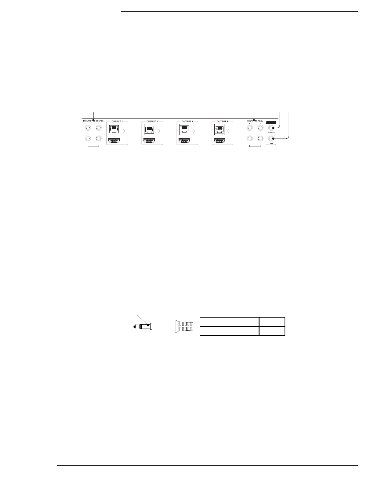
7.8.1. Matrix Switcher IR Connections
Theportsindicatedinthediagramaredescribedindetailbelow.Guidesforstandardapplicationsareincludedonthe
followingpagesforreferenceduringsetup.
7.8.2.MatrixSwitcherIRPortConguration
AllIRconnectionportsontheB-500-MTRX-230-4X4are3.5mmmonominiandusethispinoutconguration.Consult
withthemanufacturerofanyattachedIRequipmenttoconrmtheirpinoutmatchesbeforeuse.
IR Signal (Tip)
GND (Sleeve)
IR Signal Tip
GND (Ground) Ring
1. IR Output to Source 1 through 4
TheIRoutputfromeachconnectedB-500-RX-230-IRistransmittedtotheIROUTPUTTOSOURCEports.
Commandscanberoutedtothesourceselectedortothelike-numberedport.
2. IR Input to Room 1 through 4
Use3.5mmmini-monocablestoconnectIRasheroutputsonacontrolsystemtotheseportstosendcommands
todisplaysorequipmentlocatedattheB-500-RX-230-IRmatrixreceiverlocation.Thenumbercorrespondstothe
outputzonenumber,soIRInputtoRoomport1willsendsignalstoHDBaseToutput1.
3. System All IR Out
ThisportrepeatsanycommandsentfromtheIRReceiverportsonB-500-RX-230-IRMatrixReceiversconnected
to any HDBaseT output.
4. System IR In
3.5mmmonominiIRinputportformatrixswitchIRcontrol.
LINK LINK LINK LINK
1 3
2 4
1 3
2 4
1 2 3 4
B-500-MTRX-230-4x4 Installation Manual
Pg. 13
www.snapav.com Support: 866.838.5052
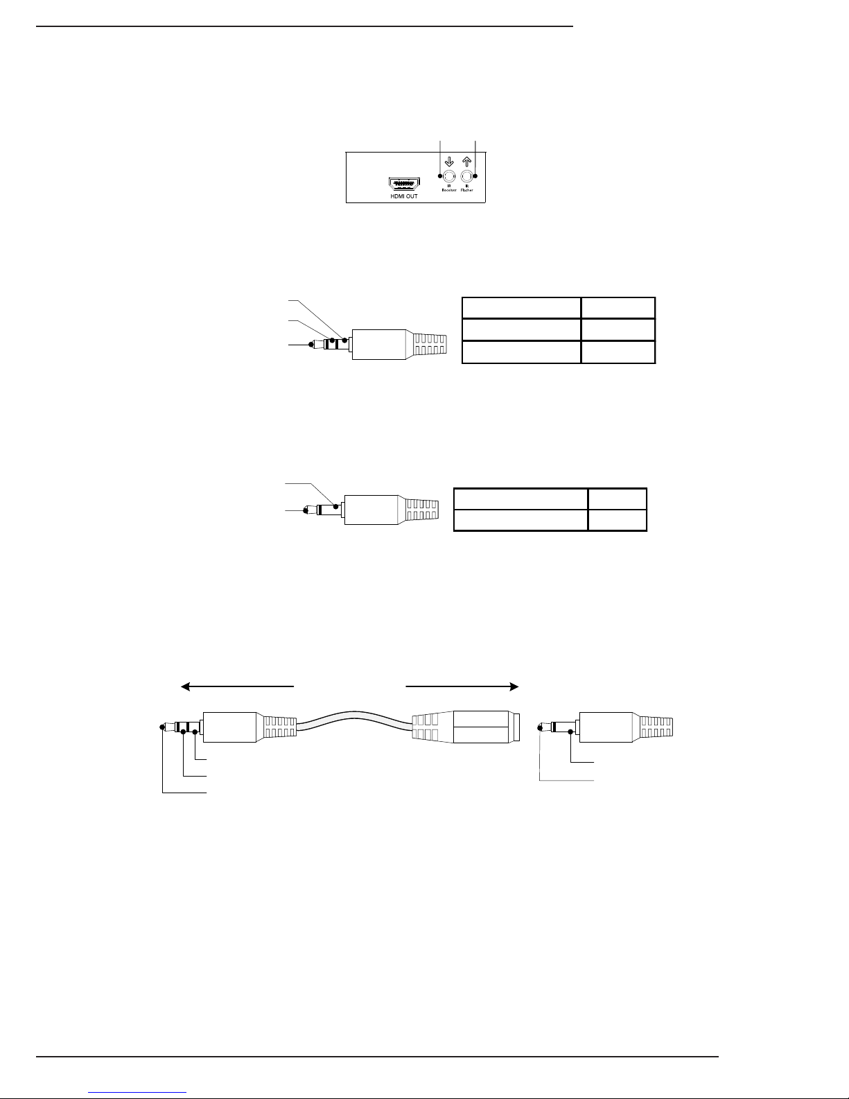
7.9. B-500-RX-230-IR IR Connections
TheB-500-RX-230-IRIRportsaredescribedbelow.Usethediagramforreference.
7.9.1. IR Receiver
AttachanIRreceivertothisporttocaptureIRcommandsintheroomforpass-throughforsources.Thisportwillalso
sendcommandsbacktothematrixswitcherforcontrolofsourceselectionineachzone.
7.9.2. IR Flasher
AttachanIRashertothisportforcontrollingadisplayorotherequipmentwithcommandssentfromacontrolsystem
asheroutput,intothematrixswitcherIRINPUTTOROOMportsandthentothisport.
1 2
IR Signal (Tip)
GND (Ring)
12V DC (Sleeve)
IR Signal Tip
GND (Ground) Ring
+12V DC Sleeve
IR Signal (Tip)
GND (Sleeve)
IR Signal Tip
GND (Ground) Ring
7.9.3. Yellow Tag IR Adapter
Theyellowtaggedadapter(illustratedbelow)includedwiththeB-500-RX-230-IRisusedwhenplugginga3.5mm
monominicableintotheIRReceiverportoftheB-500-RX-230-IR.ThisisusedtosendIRcommandstothematrix
switcherlocationfromotherdevices,insteadofanIRReceiverthatusesa3.5mmmonominiportforoutput.
IR Signal (Tip)
GND (Ring)
12V DC (Sleeve)
IR Signal (Tip)
GND (Sleeve)
To IR Control System
or
Connecting Block
To B-500-MTRX

B-500-MTRX-230-4x4 Installation Manual
Pg. 14
© 2013 Binary™
7.10. IR Application Diagrams
7.10.1. IR Pass-Through from Control System
ThediagramaboveillustratesatypicalinstallationwithaB-500-MTRX-230-4X4wherealloftheequipmentisbeing
controlledbyacontrolsystemthatusesRF(RadioFrequency)remotesineachoutputzone.
• TheRFremotestransmitcommandsbacktothecontrolsystemwhichthensendscommandstoeachdevicebeing
controlled. Custom programming by the installer sets the control system up to automatically switch inputs and
outputsinthematrixswitcherasneeded,sotheenduseronlyhastoselectthesourcetheywanttowatch.
• Eachdisplay(onlyoneispicturedforreference)requiringIRcontrolisconnectedtothesystemviatheHDBaseT
output of the matrix switcher. Cat5e/6 cable connects to a B-500-RX-230-IR Receiver, which is attached to the
displayviaHDMIforsignal.AnIRasherconnectedtotheIRasherportsendstheIRcommandstothedisplay.
Sourcesaredirectlycontrolledbythecontrolsystem.
• IR control for displays is routed from the control system to the matrix switcher using 3.5mm mono mini cables
pluggedintoIRINPUTTOROOMports.ThecommandspassfromamatrixswitcherporttotheHDBaseToutputof
thesamenumber.Inthediagramthemonocableusedtosendcommandstotheoutput4zoneispluggedintoIR
INPUTTOROOMport4.Thisallowsdiscretecontrolofeachdisplayconnected,eveniftheyaremodelswiththe
samecodes.
• SomedisplaysandprojectorscanbecontrolledbyothermethodsthanIR.TheprojectorpicturedfeaturesIPcontrol,
soitisreceivingcommandsfromthecontrolsystemoveranEthernetconnection.AnHDMIcableisconnectingitto
thematrixswitcheroutputsinceitisinstalledcloseenoughtotheequipmentandrequiresnoIRasher.
• Whenthesystemisinuse,iftwooutputsareconnectedtothesameinput,thesourcewillchangeonbothoutputs
withanycommandsentsinceitcan’tsendtwoHDMIstreamsatonce.Thismustbeconsideredwhendecidingon
thesourcestoconnectfordistribution.
Example: In a home with four displays connected, if users in every room want to watch satellite on different
channels, there must be four satellite receivers set up as sources. With custom programming, each output
can be programmed to use only one of the satellite source inputs, giving each output a dedicated cable box,
while allowing other less-used sources to connect to any output.
LINK LINK LINK LINK
1 3
2 4
1 3
2 4
24V DC 2.7A
IR Outputs RS232
IR Inputs
B-500-RX-230-IR
Projector
HDMI
Cat5e/6
HDMI
PLAY
HDMI Source HDMI Source
HDTV
IR Flasher
Ethernet Connection
RS232
IR Flasher
IR Flasher
3.5mm Mono
C5e/6
Ethernet
Connection
Cat5e/6

B-500-MTRX-230-4x4 Installation Manual
Pg. 15
www.snapav.com Support: 866.838.5052
7.10.2. IR Pass-Through from Rooms to Sources
ThediagramaboveillustratesatypicalinstallationwithaB-500-MTRX-230-4X4wherealloftheequipmentisbeing
controlledbyIRremotesineachoutputzone.
• In each room with a connected display, an entry-level universal IR remote is being used to control the display
andsourcesinuse.CustomprogrammingsetupineachremotebytheinstallersendsIRcommandsoutofthe
remotemeantforthedisplaydeviceintheroom,thesources,andthematrixswitchersimultaneously.Thematrix
commandsareprogrammedtobesentautomaticallyasneededsotheenduseronlyhastoselectthesourcethey
want to watch.
• To make this system work seamlessly, two advanced IR options have been enabled in the matrix switcher
CongurationUtility“OtherSettings”menu:IRSourceRoutingandIRMatrixControlfromroom.
o IR Source Routing allows the commands from the room to be routed directly to the source selected to be
displayedintheroom.ThissimpliesIRroutingbecauseonlyoneasherhastoconnecttothesource.
o IRMatrixControlsetsthematrixswitchersothatanycommandsentfromanyHDBaseToutputtocontrolthe
matrixisautomaticallyreceivedinternally,eliminatingtheneedforanexternalconnectionbacktothematrix
forcontrol.SeeSection9.AdvancedSetupUsingtheCongurationUtilityonpage20formoreinformationon
changing these settings.
• Whenthecommandsaresent,thedisplaydeviceiscontrolleddirectlybytheremote.Thecommandsforthematrix
switcherandsources are pickedupbythe IRreceiverconnectedtothe B-500-RX-230-IRandsentback tothe
correctIROUTPUTTOSOURCEportandtothematrix.
• Whenthesystemisinuse,iftwooutputsareconnectedtothesameinput,thesourcewillchangeonbothoutputs
withanycommandsentsinceitcan’tsendtwoHDMIstreamsatonce.Thismustbeconsideredwhendecidingon
thesourcestoconnectfordistribution.
Example: In a home with four displays connected, if users in every room want to watch satellite on different
channels, there must be four satellite receivers set up as sources. With custom programming, each output
can be programmed to use only one of the satellite source inputs, giving each output a dedicated cable box
while allowing other less-used sources to connect to any output.
LINK LINK LINK LINK
1 3
2 4
1 3
2 4
24V DC 2.7A
Projector
PLAY
HDMI Source HDMI Source
HDTV IR Receiver
IR Receiver
B-500-RX-230-IR
IR Receiver
IR Receiver
HDMI
HDMI
IR Flasher IR Flasher
HDMI
B-500-RX-230-IR
HDMI
Cat5e/6Cat5e/6

B-500-MTRX-230-4x4 Installation Manual
Pg. 16
© 2013 Binary™
8. EDIDConguration
8.1. Source Setup
8.2. Display Setup
8.3.AutoEDIDConguration
The displays used within an installation usually vary from room to room, and some may not support all resolutions
availablefromasource.Itisnecessarytomakesuresourceswillprovideavideoandaudioformatcompatiblewith
allconnecteddisplaysprogrammedtousethem.Toaccomplishthis,theB-500-MTRX-230-4X4includesbuilt-inEDID
managementforeachsourceinput.ThestoredEDIDispersource,soalldisplaylocationswillseethesameresolution
andhavethesameaudioformatwhenthatsourceisselected.
Note: Source is only able to output one video resolution and one audio format.
Note: The default EDID for each input is always 1080p with 2 channel stereo audio, since this format is accepted by
most displays with no issues.
ThefollowingsectionsexplainconguringEDIDsviatheincludedIRRemote.BeforeconguringtheEDID,besureto
refertothesourceanddisplaymanualsforavailablefeaturesandresolutionsforeachdevice.Formoreinformation
aboutusingtheincludedremote,seeSection11.1IRRemoteonpage21.
While all EDID congurations are available via the remote, the Conguration Utility can be used for faster setup.
DownloadtheCongurationUtilityandmanualontheSupportTabfortheB-500-MTRX-230-4X4atwww.SnapAV.com.
What is EDID? EDID, or Extended Display Identication Data, is a stream of information sent from a display to a source
when the two devices are connected to tell the source what video and audio formats the display can use. This prevents
sources from outputting media that won’t work with the display.
Checkeachsourceandconrmthattheaudioformatandvideoresolutionaresetsothattheywillchangebasedonthe
EDID.Normallythissettingiscalled“Auto”orsimilar.
Note: EDID setup is not required if the source supports setting one xed video resolution and audio format.
ItisrecommendedthatConsumerElectronicsControl(CEC)beturnedOFFinalldisplayswhenusingtheB-500-MTRX-
230-4X4.Thiswillprovideforpropercommunicationofvideo/audiosignalsandallowEDIDstofunctionattheiroptimum
performance.Refertothedisplay’smanualforinformationonhowtoturnthisfunctionOFF.
ThequickestandeasiestmethodforcongurationistouseAutoEDID.Whenthismodeisusedthematrixswitcher
looksattheEDIDfromeachoftheconnecteddisplays.Itusesthehighestcommonvideoresolutiontocreateanew
EDIDandsavesthatEDIDinalloftheinputs.
Note: Auto EDID sets audio to 2ch stereo for all inputs regardless of the capability of the connected displays. If multi-
channel audio is desired, embedded EDIDs or Learned EDIDs will need to be used.
When to use Auto EDID
• Allsourceswillbeavailableonalldisplays.
• Asarststeptoconguration,followingupwithadvancedmethodsforparticulardisplaysanddedicatedsources.
Note: For advanced EDID conguration when using a legacy display and/or dedicated sources, use embedded EDIDs
or learning as described in the following sections.
Sets EDID Based on All Connected Displays Display Readout (Example)
1.PressDEFAULT E-
2.PressNumberKey9 AA
3.PressENTER A0
8.3.1.HowtoCongureAutoEDID
TosetupAutoEDIDconguration,rstmakesurethatalldisplaysarepoweredonandconnectedtothematrixswitcher.
Then,pressthefollowingremotebuttonsinthisorder.Besuretopresseachbuttonwithin10secondsoftheprevious
button-presstopreventthecommandfromresetting.

B-500-MTRX-230-4x4 Installation Manual
Pg. 17
www.snapav.com Support: 866.838.5052
8.4.EmbeddedEDIDConguration
Inadditiontotheautomaticcongurationmethod,EDIDsintheB-500-MTRX-230-4X4canbesettoinputsmanuallyby
selectinganEDIDfromtheembeddedlist(defaultEDIDsprogrammedintothematrixswitcher).
Thematrixswitchercontainseight‘embedded’EDIDsthatmaybeassignedtoinputs.TheseEDIDsdenegroupsof
videoandaudiocapabilitiesthatareusefulforconguringsourcesinmostsystems.
8.4.1. Embedded EDID Chart
Explanation of Embedded EDIDs
Video ResolutionintheEmbeddedEDIDsisthehighestresolutionaconnectedsourcewilloutput.Thatis,ifthesource
iscapableof1080P@60itwillberequiredbyEDIDs1-6toprovidethatresolution.However,ifthesourceisonlycapable
of1080iitwilloutput1080i,etc.Itisassumedthatanydisplaythatcanacceptthespeciedvideoresolutioncanalso
acceptallstandardvideoresolutionslessthanthatspecied.
Color Depthisthemaximumnumberofbitsusedtoencodecolor.24bitcolordepthis8bitspercolor(red,blue,green).
36bitcolordepthis12bitspercolor(red,blue,green).
3Dindicatesthatthesourcecanoutput3Difitisavailableinthecontent.
Audio Format indicatesthemaximumnumberofaudiochannels,aswellastheaudioformatthatthesourceisallowed
tooutput.ForanEmbeddedEDIDwith7.1chAudioFormat,thesourcedevicewilloutputthehighestaudiopossible
basedonthecontent.Forexample,if7.1chisnotavailableand5.1chisavailable,thentheoutputwillbe5.1ch.The
sameistrueif2chstereoistheonlyaudioavailablefromthesource.EmbeddedEDIDswith2chstereowilllimitoutput
tothataudioformatregardlessofwhatisavailableinthecontent.
Embedded EDIDs 7 and 8areprovidedforlegacydisplaysthatcanonlyacceptresolutionsuptoamaximumof1080i/
720p.The1080iislistedrstsincealmostallolderHDdisplayscanaccept1080ibutnotallcanaccept720p.Forthese
twoEmbeddedEDIDs,(7&8)thesourcewilloutput1080i.Should1080inotbeavailable,thesourcewilloutput720p.
Note: There is a possibility that 720p may not work for a very small number of older displays that may still be in use. It
will be necessary to use a Learned EDID from the display to store in the Input EDID of any sources that will be
routed to that display if 720p is not supported. See Section 8.5. EDID Learning on page 18 for directions to set a
learned EDID.
When to Use Embedded EDIDs
• Formostcurrentdisplaysandsources,usingembeddedEDID#2isrecommendedunlessmultichannelaudiois
needed.Inthatcase,useembedded#3.TheotherembeddedEDIDsareusefulforsupportinglegacyequipment.
Embedded EDID Resolution Color Depth Audio
11080p@60Hz 24-Bit 7.1ch
2(FactoryDefault) 1080p@60Hz 24-Bit 2ch
31080p@60Hz 24-Bit 3D 7.1ch
41080p@60Hz 24-Bit 3D 2ch
51080i@60Hz 36-Bit 3D 7.1ch
61080i@60Hz 36-Bit 3D 2ch
71080i@30Hz/720p@60Hz 24-Bit 7.1ch
8 1080i@30Hz/720p@60Hz 24-Bit 2ch

B-500-MTRX-230-4x4 Installation Manual
Pg. 18
© 2013 Binary™
8.4.2. How to Set Embedded EDID for a Single Input
8.5.1. How to Learn EDID to a Single Input
8.4.3. How to Set Embedded EDID for All Inputs
Example: Input =1 Embedded EDID=4 Display Readout (Example)
1. PressDEFAULT E-
2. PressNumberKey(1-8)toselectoneEmbeddedEDID 4A
3.PressINPUT 4A
4. PressNumberKey(1-4)toselecttheInputtowhichtheEDID
isapplied 41
5. PressENTER (success)
(fail)
--
FF
Example: Input =1 Embedded EDID=4 Display Readout (Example)
1. PressDEFAULT E-
2. PressALLtoselectallInputs A-
3.PressNumberKey(1-8)toselectEmbeddedEDID 4A
4. PressENTER (success)
(fail)
--
FF
8.5. EDID Learning
FormoreadvancedEDIDconguration,learningcanbeusedtoassignEDIDsdirectlyfromdisplaystooneormore
inputs.Thisisusefulwhenthesystemcontainsadisplaythatcannotacceptthehighestresolutionavailablefrom
sources,butallsourcesneedtobeavailabletoalldisplays.
Note: EDIDs can be learned from displays connected via the HDBaseT or the HDMI output.
When to Use Learned EDIDs
• AnolderdisplaydoesnotworkproperlywithanyoftheembeddedEDIDs.
• WhenthesourceisaPCitmaybenecessarytousealearnedEDID.
• LearningEDIDtoasingleinput
Example: Input =1 EDID Learned from Output 4 Display Readout (Example)
1. PressLEARNonceforHDMIportortwiceforHDBaseTport L.-.
2.PressOUTPUT 1A
3.PressNumberkey(1-4)toselecttheOutputtheEDIDis
learnedfrom 14
4.PressINPUT L-
5.PressNumberKey(1-4)toselecttheInputtowhichtheEDID
isapplied 1A
6.PressENTER (success)
(fail)
--
FF

B-500-MTRX-230-4x4 Installation Manual
Pg. 19
www.snapav.com Support: 866.838.5052
8.5.2. How to Learn EDID to All Inputs
--
FF
Example: Input=All EDID Learned from Output 4 Display Readout (Example)
1.PressLEARN L.-.
2.PressOUTPUT L-
3.PressNumberKey(1-4)toselecttheOutputtheEDID
islearnedfrom 4A
4.PressENTER (success)
(fail)
8.6. Viewing Input EDID Status
IfthereisaquestionabouttheEDIDsetforaninput,thestatusofthatinput’sEDIDcanbereviewedusingthe
includedIRremoteandwatchingthematrixswitcherfrontpaneldisplay.
Notes about EDID Status
• IftheEDIDwaslearnedfromanoutput,theexactEDIDspecicationswillnotbeshown,buttheoutputnumberwill
beidentied.Reviewthespecicationsofthedisplayattachedtotheoutputtodetermineitscompatibleresolutions.
• If the second digit (the Input being queried) has a dot after it, then the rst digit is the EDID number from the
EmbeddedEDIDtable.
• Iftheseconddigit(theInputbeingqueried)doesnothaveadotafterit,therstdigitistheOutputtheEDIDwas
learnedfrom(step4fromexampleabove).
Example: View the EDID for Input 3.
DisplayReadout(Example)
EDID5Assigned
fromEmbedded
EDIDTable
EDIDLearned
fromOutput4
1.PressSTATUS -- --
2.PressINPUT -- --
3. PressNumberKey(1-8)toselectthedesiredInput -3 -3
4.PressENTER 5.3.4.3

B-500-MTRX-230-4x4 Installation Manual
Pg. 20
© 2013 Binary™
9. AdvancedSetupUsingtheCongurationUtility
10. Firmware Update
There are several setup options available that can only be modied using the matrix switcher Conguration Utility.
Theseitemsaredefaultedtothemostcommonsettingsthatshouldworkinmostinstallations.
TheCongurationUtilityandmanualareavailablefordownloadontheSupportTaboftheB-500-MTRX-230-4X4product
pageatwww.SnapAV.com.DownloadandruntheUtilitytogainaccesstothesesettingsbyconnectingtothematrixand
clicking“OtherSettings.”
BinarymayoccasionallyreleasenewrmwarefortheB-500-MTRX-230-4X4toaddressnewstandardsandtechnology.
Itwillneverbenecessarytoperformanupdatetoanexisting,correctlyfunctioningsystem,butduringinstallationor
serviceitisrecommendedtochecktheinstalledversiontobesureitisthenewestavailable.
Forfullupdateinstructions,seethesectiontitled,“FirmwareUpdate”intheCongurationUtilitymanual.Newrmware,
the Conguration Utility, and the Conguration Utility manual are available for download on the Support Tab of the
B-500-MTRX-230-4X4productpageatwww.SnapAV.com.
9.1. IR Source Routing
9.2. IR Front Panel IR Enable
9.4. Front Panel Power Button Active
9.3. Matrix Control from Room Enable
TheIRSourceRoutingfeatureallowsdiscretecontrolofthesourceselectedfromanyconnectedHDBaseToutputusing
anIRreceiverpluggedintotheB-500-RX-230-IR.Thissettingisonlyrelevantwhenusingin-roomIRremotestocontrol
sourcesconnectedtothematrixswitcher.WhensettoYes,thematrixwillroutecommandsfromtheHDBaseTReceiver
totheIROutputtoSourceportthatmatchesthesourceinputnumbercurrentlyselectedonthatoutput.
WhensettoNo,commandswillbesentonlyoutoftheIROutputtoSourceportthatmatchestheHDBaseTReceiver
numberfromwhichitoriginated.
ThissettingcontrolstheoperationofthefrontpanelIRreceiverbuiltintotheB-500-MTRX-230-4X4.Thisshouldbe
disabledifusingtheSYSTEMIRINporttocontrolthematrixswitcherviaIR,orifthematrixswitcherismissingor
receivingextracommandsduringuse(strayIRinterferingwiththeport).
TheFrontPanelPowerButtoncanbedisabledifdesired.Disablethebuttonwhenthematrixswitcherisprogrammedto
beonatalltimesorinjobswhereturningoffthematrixfromtheswitchercancauseissueswithcontrol.
TheMatrixControlfromRoomEnableoptionallowsMatrixControlIRcommandstobesentfromtheroomasifasource
werebeingcontrolled.Turnthisoptionoffifthematrixswitcherisbeingcontrolledbyanyothermethodthanin-roomIR.
Note: To use Matrix Control from Room, it is recommended to program a universal remote control with discrete commands
for matrix control to keep in each zone, rather than using the included IR remote or commands learned from it.
Go to the Support Tab of the B-500-MTRX-230-4X4 product page at www.SnapAV.com to see and download the
available IR codes and drivers for IR remote programming.
Default Setting: Yes
Default Setting: Yes
Default Setting: Yes
Default Setting: Yes
This manual suits for next models
1
Table of contents
Other Binary Matrix Switcher manuals

Binary
Binary B-660-MTRX-4X4 User manual

Binary
Binary B-200-AVDMATRIX-8X8 User manual

Binary
Binary 120 Series User manual

Binary
Binary B-520-MTRX-230-8x8 User manual

Binary
Binary B-660-MTRX-4X4 User manual

Binary
Binary B-210-HDMATRIX-4X4 User manual

Binary
Binary B-500-MTRX-230-8x16 User manual

Binary
Binary B-660-MTRX-8X8 User manual

Binary
Binary B-100-HDMATRIX-4X4 User manual

Binary
Binary B-120-HDMATRIX-4x4 Quick guide


