Smarte SNX-2112 User manual

for more information visit our website, or talk to one of our technical team
tel: +44 (0) 1306 628264, www.smart-e.co.uk
SNX-2112
multipoint to point daisy-chained transmitter
also available: SNX-2114 transmitter
user guide
Edition 3, July 2008
Copyright 2008 Smart-e (UK) Ltd.
Notice
The information contained in this document is subject to change without
notice. Smart-e makes no warranty of any kind with regard to this
material, including but not limited to, implied warranties of
merchantability and fitness for particular purpose.
Smart-e will not be liable for errors contained herein or for incidental or
consequential damages in connection with the furnishing, performance
or use of this material.
No part of this document may be photocopied, reproduced, or
translated into another language without prior written consent from
Smart-e (UK) Ltd.

Table of Contents
Introducing SmartNet
What ‘s in the box ..........................................................................................1
What is SmartNet...........................................................................................2
Why is SmartNet necessary .....................................................................2
How does SmartNet work ..........................................................................2
Installation and Operation
Transmitter ........................................................................................................3
Receiver Options ..............................................................................................11-29
Appendix
Specifications.....................................................................................................30
Troubleshooting................................................................................................35
Limited warranty statement ......................................................................36
Partial Product List ............................................................................................ Back

Introducing SmartLynx Cat5 AV Extender
What‘s in the box?
Thank you for buying the Smart-e SmartNet Cat5 AV Switch &
Extender. Depending on the configuration of your system various
quantities of the parts below may be included in your shipment.
If any of the accessories listed below are missing please contact the
Smart-e dealer you purchased products from or contact Smart-e
customer support at:
+44 (0) 1306 628264
If you ordered SmartNet SNX-2114/2s:
Item Description SNX-2114 SNX-2112
Master Unit 3 Inputs & 1 Cat5 Output Yes No
Slave Unit 3 Inputs, 1 Cat5 Input & 1 Cat5
Output No Yes
Power Injector Cat5 power Supply Unit No Yes
-1-
Item Description SLX-RX100 SLX-RX111 SLX-TX211
Short Range
Receiver Unit 1 Cat5 Input and 1 Output No Yes No
Long Range
Receiver Unit 1 Cat5 Input and 1 Output Yes No Yes
If you ordered SmartLynx Single Screen Receivers:
Item Description SLX-RX212 SLX-RX212D
Receiver Unit 1 Cat5 Input and 2 Outputs Yes No
Cascadeable
Receiver Unit
1 Cat5 Input, 1 Cat5 Output
2 Standard Outputs No Yes
If you ordered SmartLynx Dual Screen Receivers:

What is SmartNet?
The SmartNet systems are a combination of high quality video and audio
switches, transmitter and receiver devices designed to transmit high reso-
lution computer video and/or audio signals over Cat5 wire. AV stands for
Audio Visual and includes such signal formats as Broadcast Video (TV video
signal), Computer Video (VGA, SVGA, SXGA and etc. signals) and various
formats of Audio signals.
Why is SmartNet necessary?
Sometimes you may have numerous source devices to be displayable upon
screens. Or that AV signals need to be transmitted over distances greater
than commonly specified product limitations of 5m. In this case several
choices are available, but most are expensive and bulky, which is in some
cases simply not practical, due to space limitations in the conduits.
The SmartNet allows the transmission of AV signals over a standard Cat5
UTP cable over distances of up to 300m with full IR or RS232 control op-
tions. The actual distance is a function of the signal resolution and cable
quality. The following is a rough guide to distance and resolution:
How does SmartNet work?
The Smart-e SmartNet systems are switch/transmitter and receiver pairs
designed to extend video, stereo audio and IR/RS232 signals over (UTP &
STP) unshielded & shielded twisted pair category 5 (Cat5) cabling. They are
supplied with a UK power supply and consist of: a transmitter with a video
input (connectors vary by model), an audio input and a Cat5 output
and; a receiver with a cat5 input and corresponding outputs. Certain
Cat5 Cable Length Maximum Recommended Resolution
150m UXGA (1600x1200)
200m HDTV (720p,1080i, 1080p)
300m SDTV, SVGA (800x600)
Introducing SmartLynx Cat5 AV Extender
-2-

1. Preparing for installation
Start installation process by ensuring that all video displays and audio
devices are compatible with the computers being used.
This is accomplished by connecting the devices directly to the computer
and checking that the devices operate as desired without the SmartNet
system.
Install CAT-5 wiring between desired locations. In order to minimize system
operation difficulties, avoid routing the system cables near fluorescent
lights, air conditioners, or machines that may create electrical noise.
Installation and Operation
-3-
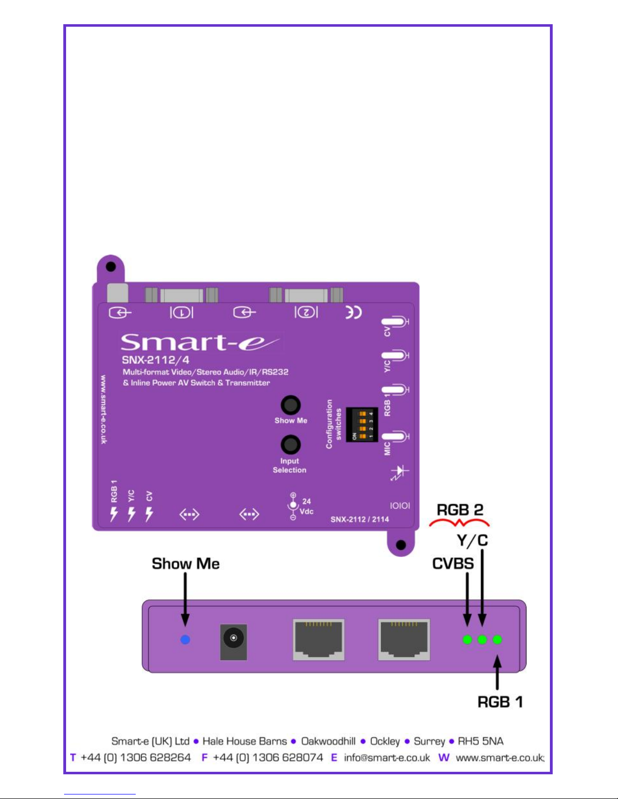
Fig. 1

2. Connect Transmitter to the signal sources
For Two High Definition (RGB/YPrPb) Sources
2.1 Connect the RGB video output of the source device to the first HD15
input on the transmitter using a standard VGA cable.
2.2 Connect the RGB or YPrPb video output of the source device to the
second HD15 input on the transmitter, using a Smart-e interface
cable if necessary.
For One High Definition + Two Standard Definition Sources
2.3 Connect the RGB video output of the source device to the first HD15
input on the transmitter using a standard VGA cable.
2.4 Connect the Y/C video output of the source device to the 4-pin
minidin connector on the transmitter using a standard Y/C cable.
2.5 Connect the CVBS video output of the source device to the RCA
connector on the transmitter, using a Smart-e interface cable if
necessary.
Installation and Operation
-4-

Installation and Operation
3. Connecting the Audio, Infra-Red & RS232 Control panel (optional)
3.1 Connect the Audio from the Source devices to the relevant 3.5mm
minijack sockets (see diagram below), using a Smart-e interface
cable if necessary.
3.2 If appropriate connect the IR emitter LED into the relevant 3.5mm
minijack socket and position the IR LED upon or near the IR window
on the device to be controlled.
3.3 If using an RS232 control panel, connect the panel to the relevant
3.5mm minijack socket, using a Smart-e Interface cable if necessary.
-5-

Installation and Operation
-6-
4. Cascading the SNX-2114 with multiple SNX-2112s
4.1 Using ‘SHIELDED’ Cat5 cable connect the Cat5 out on the SNX-
2114 to the Cat5 In on the first SNX-2112.
4.2 Repeat this step, connecting the Cat5 out on the SNX-2112s to the
Cat5 In on the following unit, for up to 32 units.
4.3 The supplied Cat5 Power Injector should be connected between
either the SNX-2114 and first SNX-2112 or, between the final SNX-
2112 and the Smart-e receiver unit. (see diagram below).
NB Units will not function unless ‘SHIELDED’ Cat5 is used to interconnect between
the SNX-2114 and SNX-2112s. However, the Cat5 from the final SNX-2112
to the receiver unit does NOT have to be shielded.

Fig. A
Fig. B
Installation and Operation
-7-
5. Configuring the Video Processing.
On the base of the unit are four switches, these are to be used to configure
the way in which the unit handles video sources. The switches functionality are
as follows:
5.1 If more than 16 units are used then the Hex Switch (see following
page) is unable to address them. To enable the addressing of units
as 17-32 then switch 1on their base should be placed to the ON
position.
5.2. Switch 2is used to enable and disable the auto-detect feature of the
units.
Switches 3 & 4 are used to determine the source priority when the auto-
detect feature is in use.
5.3 Switch 3is used to set priority to RGB 1
5.4 Switch 4is used to set priority to Y/C or RGB 2
5.5 If both switches 3& 4are set to ON - priority will be given to CVBS.
Fig. A Shows all
switches in the OFF
position,
Fig. B shows switch
1 in the ON position,
switches 2-4 in the
OFF position.

Installation and Operation
-8-
6. Allocating unique identifications to the SNX-2112s.
6.1 Using the Hex Switch on the side of the units (see diagram below),
you can provide a unique address to each unit for control purposes.
6.2 The Hex Switch has 16 unique addresses, A-F and 0-9, please
ensure that each of the units cascaded are given a different
address.
6.3 For addressing units between numbers 17 & 32 Switch 1 on the
base of the unit should be switched ON (see previous page). Units
17-32 can then be addressed in the same manner as units 1-16
above.
In Diagram to the left
the units address is set
to 9 on the Hex Switch.
Hex Switch
Installation and Operation
-9-
7. Selecting Relevant Sources and Using ‘Show Me’ Button
7.1 On the base of the unit, there is a button labelled ‘Input Selection’. By
pressing this button the unit will cycle through the inputs in
succession.
7.2 Green LEDs on the side of the unit alight corresponding to the
active input, simply continue to press the button until the correct
LED and Video source are selected (For RGB 2 both the Y/C &
CVBS LEDs will be alight).
7.3 By pressing the ‘Show Me’ button the Blue LED will alight on the side
of the currently active unit.

8. System Power up
4.1 Turn the system on by plugging in the power adapter to the
SmartLynx if they are not yet connected (See diagram
opposite).
4.2 Power up your computer.
4.3 Observe both transmitter and receiver power LED are ON,
and source device is switched on.
9. Preparing and connecting System CAT-5 cable
The SmartNet utilizes category 5 (CAT 5), unshielded twisted pair (UTP) cable to
transport signal between transmitter and receiver and shielded twisted pair (STP)
to transport signals between SNX-2114s and SNX-2112s..
CAT 5 cable is more desirable than coaxial cable due to its low cost and ease of
installation. This cable is used for LAN applications and is found in abundance,
already installed, in many buildings . The category 5 is a standard which estab-
lishes minimum requirements for telecommunications cabling within a commer-
cial building. The standard covers various aspects of wiring including telecommu-
nications outlets.
Following is the wiring standard for terminating CAT 5 cable using RJ 45 connec-
tor:
Pair 1 Pins 1 & 2
Pair 2 Pins 3 & 6
Pair 3 Pins 4 & 5
Pair 4 Pins 7 & 8
Connectors: RJ-45
Capacitance: 14 pf/ft (46.2 pf/m)
Conductor Gauge: 24 AWG
Impedance: 100 +/- 15 ohms
4 - Pair
Installation and Operation
-10-
Receiver Options
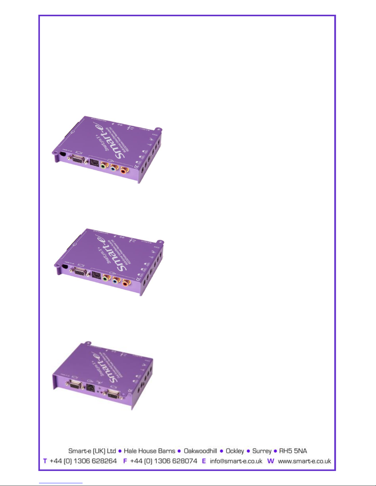
10. Smartlynx Receiver Options
There are a number of different receiver options available to accompany the SLX-TX16,
please check the model number and relevant page number reference below.
SLX-RX111
UXGA, RGBS, RGsB, YPrPb, Y/C, CVBS, Stereo
Audio and RS232 or Infra-Red control option.
For Instructions on Installation of the SLX-RX111 see page………………………………………………12
SLX-RX211
Same as SLX-RX111 but with greater range and
skew compensation.
For Instructions on Installation of the SLX-RX211 see page………………………………………………15
SLX-RX212/D
Dual Screen Output, UXGA, RGsB, YPrPb, Y/C, CVBS
and Stereo Audio, with RS232 or Infra-Red control
option. SLX-RX212D can be cascaded.
For Instructions on Installation of the SLX-RX212 see page………………………………………………18
-11-

The SLX-RX111 allows for the Short Range reception of UXGA,
RGsB, RGBS, YPrPb, YUV and Long Range reception of Y/C,
CVBS, Stereo Audio, and Infra-Red or RS232 control signals,
when broadcasted along a single Cat5 UTP cable from a Smart
-e transmitter or matrix.
The signals are received along the Cat5 from the transmitter
and then distributed to the display and control equipment via
the appropriate connection and to speakers via a 3.5 mm mini
-12-
Installation and Operation—SLX-RX111
SLX-RX111

1. Connecting SLX-RX111 to the display device
1.1 Making sure that the Cat 5 cable is connected to the transmitter
output, connect the cable to the RJ45 socket on the receiver unit.
1.2 If the cable connection is correct the power LED on the front of the
receiver should illuminate (power is sent up the Cat 5 cable).
1.3 Connect the display to relevant connector on the receiver
(see diagram below) using the appropriate cable.
1.4 If RS232 control is required then connect to the display via the
3.5mm minijack on the receiver using a CAB-J19-1M.
Installation and Operation—SLX-RX111
-13-

2. Connecting SLX-RX111 to audio and Infra-Red control
2.1 Connect the speakers or audio input on the display to the audio
output on the receiver, using a 3.5mm jack plug.
2.2 If using the receiver to transmit Infra-Red signals back down the
cable to the transmitter unit then connect an ‘eye’ to the jack
position as shown in the diagram below.
2.3 If using the receiver to transmit Infra-Red signals up to the display
from the transmitter unit then connect a ‘LED’ to the jack position
as shown in the diagram below.
Please note: connecting the IR ‘eye’ will prevent the return RS232 path from the display
Installation and Operation—SLX-RX111
-14-

3. Mounting the Receiver
The receiver unit can compensate for cable losses over a length of 20-100m, and for
mounting purposes the unit is provided with two ’mounting-hole’ points for fixing to the
wall or screen (See diagram below). Simply hold receiver in place, mark position of holes
and set screws in these locations.
NB. Always use screws with heads larger than the holes.
‘MOUNTING-HOLES’
‘MOUNTING-HOLES’
Installation and Operation—SLX-RX111
-15-

SLX-RX211
The SLX-RX211 allows for the Long Range reception of UXGA,
RGsB, RGBS, YPrPb, YUV, Y/C, CVBS, Stereo Audio, and Infra-
Red or RS232 control signals when broadcasted along a single
Cat5 UTP cable from a Smart-e transmitter or matrix.
The signals are received along the Cat5 from the transmitter
and then distributed to the display and control equipment via
the appropriate connection and to speakers via a 3.5 mm mini
jack.
-16-
Installation and Operation—SLX-RX211

1. Connecting SLX-RX211 to the display device
1.1 Making sure that the Cat 5 cable is connected to the transmitter
output, connect the cable to the RJ45 socket on the receiver unit.
1.2 If the cable connection is correct the power LED on the front of the
receiver should illuminate (power is sent up the Cat 5 cable).
1.3 Connect the display to relevant connector on the receiver
(see diagram below) using the appropriate cable.
1.4 If RS232 control is required then connect to the display via the
3.5mm minijack on the receiver using a CAB-J19-1M.
Installation and Operation—SLX-RX211
-17-
Table of contents
Other Smarte Transmitter manuals


