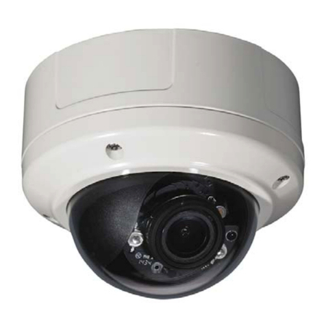
Smartec STC-3904 User manual

Smartec STC-3904/3902/3905
Day/Night High-Speed Dome Cameras
User Manual
www.smartec-security.eu

CONTENTS
Warning & Caution ------------------------------------------------------------------------------ 3
What's in the Box -------------------------------------------------------------------------------- 3
General Fratures --------------------------------------------------------------------------------- 4
Names of Each Part ----------------------------------------------------------------------------- 5
Installation ----------------------------------------------------------------------------------------- 6
A. Connection Method ------------------------------------------------------------------- 6
B. Ceiling Mount Type ------------------------------------------------------------------- 8
C. Embedded Mount Type ------------------------------------------------------------- 9
D. Pipe Mount Type --------------------------------------------------------------------- 10
E. Gooseneck Mount Type-------------------------------------------------------------- 12
F. Wall Mount Type----------------------------------------------------------------------- 13
G. Corner Mount Type ------------------------------------------------------------------- 14
H. Pole Mount Type ---------------------------------------------------------------------- 15
I. Indoor Housing Adaptor Type ------------------------------------------------------ 16
Ouick Operating Keys---------------------------------------------------------------------------- 18
Diagnostic------------------------------------------------------------------------------------------- 20
OSD Menu Setting--------------------------------------------------------------------------------- 21
A. OSD Menu Table --------------------------------------------------------------------- 21
B. DOME SET ----------------------------------------------------------------------------- 22
C. CAMERA SET ------------------------------------------------------------------------- 28
D. PRESET ------------------------------------------------------------------------------- 30
E. AUTO SCAN SET--------------------------------------------------------------------- 31
F. TOUR SET------------------------------------------------------------------------------ 32
G. PRIVACY SET ------------------------------------------------------------------------- 33
H. PATTERN SET------------------------------------------------------------------------- 34
I. ALARM SET --------------------------------------------------------------------------- 35
J. ALARM SET --------------------------------------------------------------------------- 36
DIP Switch Setting -------------------------------------------------------------------------------- 37
A. ID Setting ------------------------------------------------------------------------------- 37
B. 485 Termination------------------------------------------------------------------------ 39
C. Protocol --------------------------------------------------------------------------------- 39
D. Baud Rate Setting--------------------------------------------------------------------- 39
Trouble shooting ---------------------------------------------------------------------------------- 40
Specification---------------------------------------------------------------------------------------- 41
Dimensions ----------------------------------------------------------------------------------------- 42

CAUTION
RISK OF ELECTRIC SHOCK
DO NOT OPEN
CAUTION:
TO REDUCE THE RISK OF ELECTRIC SHOCK,
DO NOT REMOVE COVER (OR BACK).
NO USER SERVICEABLE PARTS INSIDE.
REFER SERVICING TO QUALIFIED SERVICE PERSONNEL.
WARNING & CAUTION
If you fail to read this information and handle
the product incorrectly, death or serious
injury may occur.
The unit should be installed by the trained
personnel
This symbol is intended to alert the user to the
presence of uninsulated "dangerous voltage"
within the product's enclosure that may be of
sufficient magnitude to constitute a risk of electric
shock to persons.
This symbol is intended to alert the user to the
presence of important operating and maintenance
(servi
cing) instructions in the literature
accompanying the appliance.
1. Camera
2. Ceiling Mount Bracket
3. Wrench
4. Screw (Ø3x6 screw---------2EA,
Ø4x16 screw-------5EA)
5. Safety Wire
6. Manual
7. Ceiling Cover
8. Cable ties
9. Terminal Block
(2 Pin--------------------------2EA,
3 Pin, 5 Pin, 6 Pin --------1EA)
What's in the Box ?
Switch off immediately if the product emits
smoke or abnormal heat.
Never install the product in area exposed oil or
gas.
Never install the product on a ceiling that cannot
hold its weight.
Never touch the power cord with wet hands.
Clean only with dry cloth.
Never install the product in extreme high or low
temperature.
Never drop, hit strongly nor vibrate the product.
Never expose the product to direct sunlight or
severe ray.
Never touch the front glass of the product.
Never install the product in areas exposed to
rain or water.

GENERAL FEATURES
World most silent speed dome camera
Equipped with silent and smooth timing belt and
special gear, low-noisy-technology enhances
durable quality of the camera by reducing the
mechanical vibration. This camera is the perfect
match, both indoor and outdoor, for demanding
security and monitoring burglars.
0.024º dome system accuracy with 1/8
micro step
With 0.024º technical accuracy, camera provides
excellent sensitive and delicate controlling on
preset mode by adapting 1/8 micro step and twin
gear system
Reliable RAM-Material
The mechanical stabilization improves the
durability and long life time of the camera by
using reliable materials especially, stepping
motor, slip ring, timing belt and power condenser.
This camera case is made of fire resisting
material that approved UL grade 94 V-0. It is
useful for indoor environment concerning about
the fire accident
Compensation function: preset position
The function provides absolute preset position
even in difficult applications where vibration and
strong winds may otherwise affect dome
performance.
Slip Ring for long life time (20milion
rotate ring tested)
Equipped with slip ring is passed by up to 20
millions rotate ring test within 6 months
Power misconnection protection on 485
terminals
This protection function prevents the
communication terminal from being out and
trouble when power source falsely connects to
the RS-485 terminals. Hi speed dome got a
patent for power misconnection protection on
RS-485 terminal
Filter changeable True Day/Night
Top quality images are assured under day and
night conditions due to the true day / night
camera with IR cut filter. Low light sensitivity is
further increased by the cameras digital slow
shutter.
Quick Operation Keys
This camera provides quick function keys to
allow control by most keyboards and DVRs that
have Pelco protocol support..
Various Surveillance Functions
Auto Scan repeats pan and tilt between two
preset positions with different speed and dwell
time.
8 Group Tour up to 8 Programmable Group
tours available and each group is consisting up to
60 presets step with different speed and dwell
time with 16 characters.
165 Preset positions up to 165 programmable
preset positions are available with 16 characters
8 Patterns up to 8 programmable user-defined
patters are available with 16 characters and each
one is consisting 50 seconds, total 400
8 Sectors up to 8 programmable user-defined
sectors are available with 16 characters
24 Privacy Masking Zones up to 24
programmable user-defined privacy masking
zones are available with 16 characters (18X, 26X
only)
4 Alarm input and 2 relay out up to 4 alarms
and 2 relay out available to match with preset,
tours, patterns.
300º/S 200O/S on Preset speed
The 360º full pan function moves through a
maximum of 350º /sec., enabling you to quickly
pinpoint the spot you want to watch. Tilt speed
provides through a maximum 250º /sec on
preset. On preset mode, the camera is set up to
300º /sec
200º /S Manual speed
This camera provides up to 200º /sec of manual
speed and it's adjustable from 100º /sec to 200º
/sec
1/4'' Sony Ex-View CCD
Equipped with Sony Ex-view HAD CCD
technology, these particular cameras provide
excellent sensitivity and low smear levels (18X
26X only)
Multiple languages and protocols
To convenience for the customers, this camera
provides several languages and protocols
including English, Italian, Polish and Pelco D,
Pelco P and Ultrak protocol
Intelligent Pan/Tilt Controlling
Pan and tilt speed compensation function linked
to zoom position

NAMES OF EACH PART
FIG. 1
1. Bubble
2. Lock Screw
3. DIP Switch 1
4. DIP Switch 2
5. Camera
6. Lock Holder
7. Power
8. Video Output
9. Loop RX
10. Loop TX
11. Power LED
12. Aux
13. Alarm
14. Mount Holder

INSTALLATION
A. CONNECTION METHOD
A-1. To separate camera body
Loosen Lock Screw 2mm to the counterclockwise using the wrench.
(Don't pull out the screw) (FIG. 2)
Separate the upper body from the lower body rotating counterclockwise. (FIG. 3, 4)
A-2. After separating, set DIP switches. (Refer to the page 37, 38 and 39)
A-3. To assemble camera body
Rotate the upper body clockwise to assemble both bodies (FIG. 5, 6)
Screw up using wrench clockwise. (FIG. 7)
●Don't screw tightly. It can be the cause of defect.
FIG. 2 FIG. 3 FIG. 4
FIG. 5
Screw up to flat with
the body surface.
LOCK
FIG. 6 FIG. 7
UNLOCK

INSTALLATION
A-4. Alarm : 4 Alarm input
A-5. AUX : DC 24V 1A can be used as an AUX terminal.
Turning on the light and remote control are possible using AUX.
A-6. TX : TX transmits Data signal received from RX to other equipment.
TX is convenient terminal for connection with Daisy Chain.
A-7. RX : RX are received Control Signal from controller or DVR.
A-8. Video out : BNC connector
A-9. Power : AC 24V 1.0A adaptor
●Don't connect power source to Center terminal of Power.
A-10. Power on LED
IR SENSOR or DOOR SENSOR
AUX 2
AUX 1
SIGNAL
GND
(2,3,4 Same way of 1)
AUX 2
TERMINAL BLOCK
(FEMALE)
AUX 2
MONITOR
TERMINAL BLOCK
(MALE)
AC220/110V
AC24V ADAPTOR
CONTROLLER or DVR
OTHER CAMERA or DEVICE
FIG. 8

INSTALLATION
B. CEILING MOUNT TYPE
B-1. Find the places which are strong enough to support the camera, about 2kg.
B-2. Make a hole, Ø145mm, on the ceiling. (FIG. 9)
Hook the safety wire to suspension and the safety wire hold on the bracket. (FIG. 10)
B-3. Install the ceiling mount bracket by driving 4 screws, Ø4mm tapping screws. (FIG. 11)
B-4. You can make wires simple by cable ties. (FIG. 12)
B-5. Make the wires go though the square hole.
Insert mount holder and twist the camera counterclockwise. (FIG. 13)
B-6. Fix the camera by driving a screw on lock holder1 and 2. (FIG. 14)
B-7. Install the cover by inserting cover lock and twisting clockwise. (FIG. 15)
1. CEILING MOUNT BRACKET 1ea
CONTENTS
SUSPENSION
SAFETY W IRE
COVER HOLE
LOCK HOLDER 1.
SCREW (Ø4.0)
CEILING BRACKET
SAFETY W IRE HOLE MOUNTING HOLE
LOCK HOLDER 1.
CABLE TIE
LOCK HOLDER 2.
MOUNT HOLDER
FIG. 10
FIG. 9 FIG. 11 FIG. 12
SCREW (M3.0)
COVER
COVER HOLE
COVER LOCK
FIG. 13 FIG. 14
FIG. 15

INSTALLATION
C. EMBEDDED MOUNT TYPE
C-1. Prepare a Ø190mm hole in the ceiling board.
Fix the safety wire to a suspension to prevent camera from falling.
Other side of safety wire is fixed to the safety wire hole. (FIG. 16)
C-2. Fold the Lock Levers then insert the Bracket into the Ceiling Hole.
Fix the Bracket to the ceiling using the driver. (FIG. 17)
C-3. Hereafter installation is same way of Ceiling Mount Type. (Refer to the page 8)
1. EMBEDDED MOUNT BRACKET 1ea
CONTENTS
SAFETY W IRE HOLE
FIG. 16
LOCK LEVER
LOCK LEVER
LOCK LEVER
EMBEDED MOUNT
LOCK LEVER
FIG. 17
FIG. 18
SCREW (M3.0)

INSTALLATION
D. PIPE MOUNT TYPE
D-1. If you want to install the speed dome on the concrete wall, you need to make
12.5mm diameter 4 holes by drill like FIG. 19. (Depth 37mm)
D-2. Install SET ANCHOR BOLT on the holes.
D-3. Drive a cap on the pipe. (FIG. 20) .
D-4. After winding the THREAD SEAL TAPE, screw the bracket on the housing. (FIG. 21)
D-5. Fix SET ANCHOR BOLT of the bracket by nut.
1. PIPE MOUNT BRACKET 1ea 2. SET ANCHOR BOLT (W5/16) 4ea
3. CAP 1ea
CONTENTS
FIG. 19
4-Ø12.5mm Hole
Cap
THREAD SEAL TAPE
FIG. 20
FIG. 21

INSTALLATION
D-6. Tie the wire using the cable ties. (FIG. 23)
D-7. Place the Camera Mount Holder on the Bracket Mount Hole.
To insert them easily, keep 10° interval of Lock Holder1 and Lock Holder2. (FIG. 24)
D-8. Screw up the bubble tightly to prevent water leakage. (FIG. 25)
FIG. 22
<The cable into ceiling> <The cable out of ceiling>
LOCK HOLDER 1.
FIG. 23 FIG. 24
FIG. 25
LOCK HOLDER 2.
MOUNT HOLDER
CABLE TIE

INSTALLATION
E. GOOSENECK MOUNT TYPE
E-1. If you want to install the speed dome on the concrete wall, you need to make
12.5mm diameter 4 holes by drill like FIG. 26. (Depth 37mm)
E-2. Install SET ANCHOR BOLT on the holes.
E-3. Drive a cap on the pipe. (FIG. 27)
E-4. After winding the THREAD SEAL TAPE, screw the bracket on the housing. (FIG. 28)
E-5. Fix SET ANCHOR BOLT of the bracket by nut.
E-6. Camera installation is the same as that of Pipe mount bracket installation.
(Refer to page 11)
1. GOOSENECK MOUNT BRACKET 1ea 2. SET ANCHOR BOLT (W5/16) 4ea
3. CAP 1ea
CONTENTS
FIG. 26
4-Ø12.5mm Hole
Cap
THREAD SEAL TAPE
FIG. 27 FIG. 28
FIG. 29
<The cable into ceiling> <The cable out of ceiling>

INSTALLATION
F. WALL MOUNT TYPE
F-1. If you want to install the speed dome on the concrete wall, you need to make
12.5mm diameter 4 holes by drill like FIG. 30. (Depth 37mm)
F-2. Install SET ANCHOR BOLT on the holes.
F-3. Fix SET ANCHOR BOLT of the bracket by nut.
To install Wall Mount Bracket.
Tip> Select a ceiling board strong enough to hold 4 times the total weight if camera.
(Weight combined camera: approx. 5kg)
F-4. Screw up the Bracket tightly using the wrench(M4.0) after putting the rising into
the hole. (FIG. 31)
F-5. Camera installation is the same as that of Pipe mount bracket installation.
(Refer to page 11)
1. WALLMOUNTBRACKET1ea 2. SETANCHORBOLT(W5/16)4ea
CONTENTS
FIG. 30
4-Ø12.5mm Hole
<The cable out of ceiling>
FIG. 31

INSTALLATION
G. CORNER MOUNT TYPE
G-1. First mark the position of holes placing the corner mount bracket.(FIG. 33)
Make Ø12.5mm 4 holes by drill. (Depth 37mm)
G-2. Install SET ANCHOR BOLT on the holes.
G-3. Fix the wanted bracket (wall mount bracket, gooseneck mount bracket) on the corner
mount bracket with 4ea of M10 bolt before you Install the corner mount bracket.(FIG. 34)
G-4. Screw the set anchor bolt of the bracket by nut on the wall. (FIG. 35)
G-5. Housing and camera installation is the same as that of Pipe mount bracket installation.
(Refer to page 10, 11)
<The cable into ceiling>
1. CORNER MOUNT BRACKET 1ea 2. SET ANCHOR BOLT (W5/16) 4ea
3. M10 BOLT & NUT 4ea
CONTENTS
FIG. 33
Mark the positions of holes
M10.0 BOLT
GOOSENECK MOUNT BRACKET
CORNER MOUNT BRACKET
CORNER MOUNT BRACKET
FIG. 35
FIG. 34

INSTALLATION
H. POLE MOUNT TYPE
H-1. Fix the wanted bracket on the corner mount bracket with 4ea of M10 bolt before you Install
the corner mount bracket. (FIG. 36)
H-2. Tie the bracket with sus band tightly. (FIG. 37)
H-3. Housing and camera installation is the same as that of Pipe mount bracket installation.
(Refer to page 10, 11)
1. POLE MOUNT BRACKET 1ea 2. SUS BAND 2ea
3. M10 BOLT & NUT 4ea
CONTENTS
WALL MOUNT BRACKET
FIG. 36
FIG. 37
POLE MOUNT BRACKET
M10 BOLT
SUS BAND

INSTALLATION
I. INDOOR HOUSING ADAPTOR TYPE
I-1. After screwing pipe nut on the pipe and inserting it into housing, fix the pipe with housing
By screwing the nut again. (FIG. 38)
I-2. Fix the ceiling bracket on the housing by M4.0 screw. (FIG. 39)
I-3. Tie the wire using the cable tie. (FIG. 39)
I-4. Let the wires to be put into the square hole. (FIG. 39)
Place the Camera Mount Holder on the Bracket Mount Hole.
To insert them easily, keep 10° interval of Lock Holder1 and Holder 2.
1. INDOORHOUSING 1ea 2. PIPENUT2ea
CONTENTS
PIPE NUT
FIG. 38
LOCK HOLDER 1.
CABLE TIE
FIG. 39
MOUNT HOLDER
LOCK HOLDER 2.
SCREW (Ø4.0)
CEILING BRACKET
MOUNTING HOLE
SAFETY W IRE HOLE
LOCK HOLDER 1.
COVER HOLE

INSTALLATION
I-5. To assemble, rotate the camera clockwise by 10°. (FIG. 40)
I-6. Screw up Lock Holders with screws. (FIG. 41)
I-7. Assemble the cover.
Fix three Cover Locks to three Cover Holes rotating clockwise. (FIG. 42)
FIG. 40
SCREW (M3.0)
LOCK HOLDER 1.
LOCK HOLDER 2.
FIG. 41
COVER HOLE
COVER LOCK
FIG. 42

QUICK OPERATING KEYS
The dome supports Pelco-D/P, SAMSUNG and VICON protocols.
The dome may be used with any controller or DVR etc that supports the Pelco D and Pelco
P protocols.
The default setting of the dome is Pelco D / P (auto detection) with 2400 bps (baud rate).
[PELCO D/P PROTOCOLS]
The comprehensive feature set of the dome is available from Pelco compatible controllers
via quick operation keys as defined below.
1-64 + preset and 100~200 + preset are used for normal user presets.
Presets 65-99 + are reserved for special functions.
For example, to enter OSD MENU, press the button 95 + PRESET
<Quick Operation Key Table 1>
Number Note Function
1~64,100~200 +Preset Preset Executing Preset 1 ~ 64, 100~200
65 +Preset Preset Status Display Preset Status
66 +Preset Auto Scan Executing Auto Scan
67 +Preset Auto Flip Selectable On/Off in Auto Flip mode
68 + Preset Camera Reset Re-setting Zoom camera module
70 + Preset VIB CORR Selectable On/Off in Picture Stabilization function
71~78 + Preset Group Tour Executing Group Tour #1 ~ #8
81~88 + Preset Pattern Executing Pattern #1 ~ #8
91 + Preset Zero Position Searching Pan / Tilt Zero Position
92 + Preset Freeze Select Freeze image when camera is working
93 + Preset BLC Selectable On/Off in BLC function
94 + Preset Day / Night Selectable Day / Night / Auto Mode
95 + Preset OSD Entering OSD Main Menu
96 + Preset Focus Adjust Focus adjust
97 +Preset Alarm Selectable Enable/Disable all Alarms
98 +Preset AUX 1 Selectable On/Off in Aux1
99 +Preset AUX 2 Selectable On/Off in Aux2
<Quick Operation Keys Table 2: Use these function keys if controller has these keys>
Menu Function
Tilt Up / Down Sub menu cursor moves up / down
Pan Left / Right Enter to the sub menu or status change or decrement
Focus Near Using for Enter key when user select YES or NO
Focus Far Using for function changing keys when set coordinate
Zoom Tele Status cursor to the right
Zoom Wide Status cursor to the left
●65 + preset : "Preset Status" is displayed, to remove this screen, press Focus Near button.
●70 + preset : This feature provides picture stabilization image and it is by EX980S (P)
module only.
This feature is operating by preset number but not included in OSD main menu.
This is optional function due to zoom module

QUICK OPERATING KEYS
●92 + preset : This feature freezes the current live image during tour, auto scan or pattern
operation. When you press 92 + preset button, the image freezes but the camera is still
working as per operation such as tour, pattern or auto scan. To return to normal images,
press 92 + preset button again.
This feature is operated by preset number but not included in OSD main menu.
●Due to Zoom camera module, OSD Menu not provides every feature.
In this case, "Not available" is displayed on the monitor.
[MAXPRO PROTOCOL]
If user wants to choose Maxpro Protocol, the user may change the dip switch first.
(Refer to Page #32 DIP SWITCH SETTING - PROTOCOL)
Baud Rate: 9600 (Maxpro default)
Maxpro protocol is almost same as Pelco D/P protocol operating system but some special
features are different way as noted below
<Quick Operation Key Table 1>
Number Note Function
1~64,100~200 +Preset Preset Executing Preset 1 ~ 64, 100~200
67 +Preset Auto Flip Selectable On/Off in Auto Flip mode
80~85 + Preset Pattern Executing Pattern #1 ~ #6
86 + Preset Auto Scan Executing Auto Scan
87~89 + Preset Group Tour Executing Group Tour #1 ~ #3
90 + Preset OSD Entering OSD Main Menu
91 + Preset Zero Position Searching Pan / Tilt Zero Position
92 + Preset Freeze Select Freeze image when camera is working
93 + Preset BLC Selectable On/Off in BLC function
94 + Preset Day / Night Selectable Day / Night / Auto Mode
95 + Preset OSD Entering OSD Main Menu
96 + Preset Focus Adjust Focus adjust
97 +Preset Vir. Corr. Selectable On/Off in Vibration Correction function
98 +Preset AUX 1 Selectable On/Off in Aux1
99 +Preset AUX 2 Selectable On/Off in Aux2
<Quick Operation Keys Table 2: Use these function keys if controller has these keys>
Menu Function
Tilt Up / Down Sub menu cursor moves up / down
Pan Left / Right Enter to the sub menu or status change or decrement
Focus Near Using for Enter key when user select YES or NO
Focus Far Using for function changing keys when set coordinate
Zoom Tele Status cursor to the right
Zoom Wide Status cursor to the left
●Due to Zoom camera module, OSD Menu provides not every feature. In this case,
“Not available” is displayed on the monitor.

DIAGNOSTIC
Whenever the dome is powered on, a standard diagnostic is operated.
A. Pan Origin Test
Zero point of Pan is located during the Panning test.
B. Tilt Origin Test
Zero point of Tilt is located during the Tilt test.
C. TX connection Test
Wait for 60 seconds for TX Connection Test,
During 60 seconds, the camera is must received a signal by any control equipment
as DVR or controller.
Then Ok is displayed then automatically verifying TX Connection Test.
* If "Not Tested" is displayed in the test,
- The result which is not received any signal from DVR or controller
- Wrong connecting way such as the protocol, baud rate or RS-485 connection.
The use may check the install way carefully.
D. Camera Comm. Test
Camera communication is also checked.
OK should be displayed in these four tests before installation.
If all the above Tests are OK, “NOW EEPROM CHECKING” and “ALL DATA INITIALIZING” is
displayed and the camera is ready to operate.
CAMERA ID : 001
BAUD RATE : 2400 BPS
WAITING………
PAN ORIGIN TEST OK
TILT ORIGIN TEST OK
TX CONNECTION TEST OK
CAMERA COMM TEST OK
This manual suits for next models
2
Table of contents
Other Smartec Security Camera manuals
Smartec
Smartec STC-IP2580 User manual
Smartec
Smartec STC-3502 User manual
Smartec
Smartec STC- 3080 ULTIMATE User manual

Smartec
Smartec STC-IPM3090A Instructions for use
Smartec
Smartec STC- 3670 User manual

Smartec
Smartec STC-3900 User manual
Smartec
Smartec STC-2430/1 User manual
Smartec
Smartec STC- 3080 ULTIMATE User manual

Smartec
Smartec STC-3580 ULTIMATE User manual

Smartec
Smartec STC-3002 User manual

