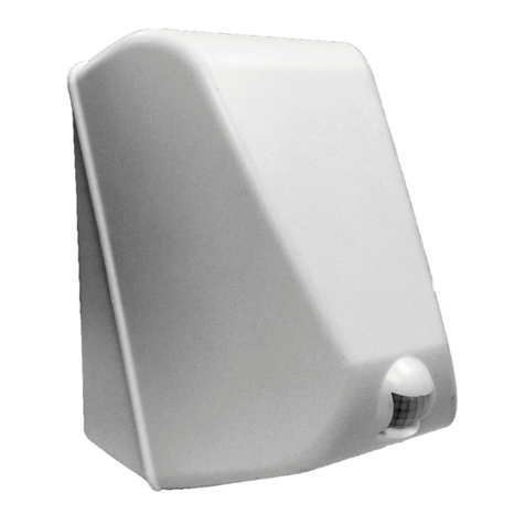
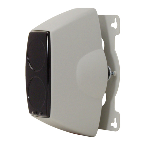
Smartek NB40F3UX User manual

NB40F3UX – NB40S2UX – NB40LP2UX - NB40LPS2UX
REV 01 – Dec. 2019 - ENGLISH
NUBI 4.0
AVAILABLE MODELS
Model Power Supply PIR
NB40F3UX 10-15VDC <0,1mA YES
NB40S2UX 10-15VDC <0,1mA NO
NB40LP2UX Lithi m battery 3,6V YES
NB40LPS2UX Lithi m battery 3,6V NO
Thank yo for p rchasing NUBI 4.0, the intelligent smoke
screen sec rity device able to be connected to any b rglar
alarm system in new or existing systems.
OPERATIONAL OVERVIE
NUBI 4.0 is an accessory for anti-theft systems which,
nder certain conditions, activates the smoke caps le
ho sed inside. The caps le is packaged and s pplied
separately. NUBI 4.0 m st be connected to an b rglar
alarm control nit via its inp ts and o tp ts.
Activating the smoke caps le does not req ire any over-
c rrent from the power so rce, since the necessary energy
has already been stored by the motherboard.
The XAFER S25 smoke caps le efficiently protects
vol mes p to 100 m3. The smoke generated ses
pyrotechnic technology and incense; it is not classified as
harmf l to h man health. After se, the room m st be
ventilated before staying there.
NUBI 4.0 is activated thro gh 3 inp ts, one of which to
control the immediate emission of smoke (override input),
while the other two create a more complex logic which,
when present, also incl des the se of the internal infrared
sensor.
The polarity of the inp ts can be easily config red sing
the DIP switches.
NUBI 4.0 also has three o tp ts, one for tampering, one
for alarm and one for anomaly. The logic of the o tp ts can
be inverted sing the DIP switches.
Devices eq ipped with an infrared sensor also have the
possibility to change the defa lt behavior thanks to a
special config ration f nction that m st always be
performed via the DIP switches.
An optional internal siren (NBSR01) can be ho sed inside
the box and connected to the dedicated connector on the
motherboard.
An optional accessory (NBTMPX) is available for
advanced tamper protection which contains sensors for
vibrations, heat, proximity and antifoam.
The smoke caps le works only once, the smoke emission,
when activated, can no longer be interr pted.
The replacement of the smoke caps le is very simple,
each replacement caps le is eq ipped with an electronic
card at the end of the wires to be easily connected to the
appropriate motherboard connector.
See o r website: https://www.smarteksrl.it to check the
availability of this man al in other lang ages.
INSTALLATION
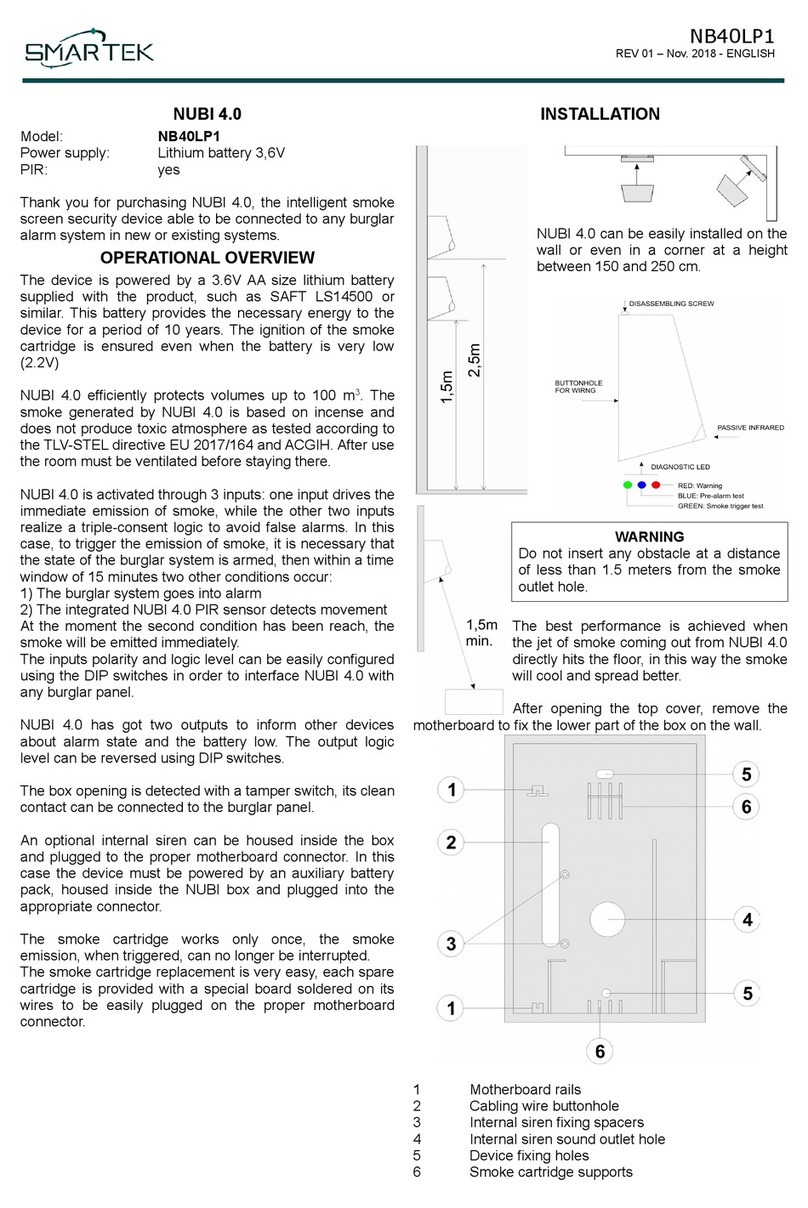
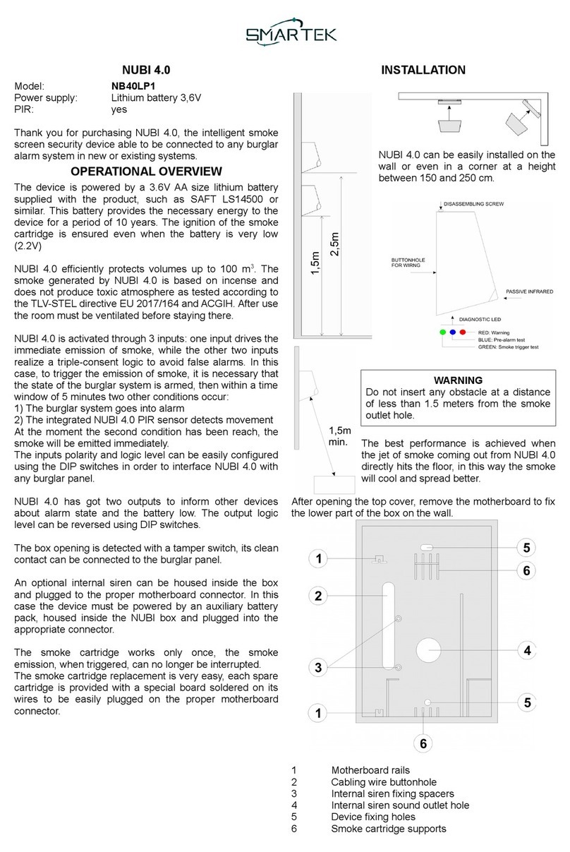
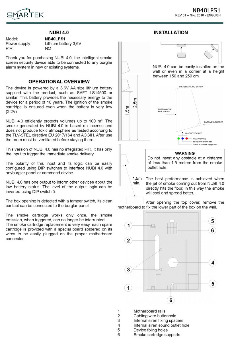
NUBI 4.0 can be easily installed on the
wall or even in a corner at a height
between 150 and 250 cm.
ARNING
Do not insert any obstacle at a distance
of less than 1.5 meters from the smoke
o tlet hole.
The best performance is achieved when
the jet of smoke coming o t from NUBI 4.0
directly hits the floor, in this way the smoke
will cool and spread better.
After opening the top cover, remove the motherboard to fix
the lower part of the box on the wall.
1 Motherboard rails
2 Cabling wire b ttonhole
3 Internal siren fixing spacers
4 Internal siren so nd o tlet hole
5 Device fixing holes
6 Smoke cartridge s pports

NB40F3UX – NB40S2UX – NB40LP2UX - NB40LPS2UX
REV 01 – Dec. 2019 - ENGLISH
MAINBOARD(s)
10..15VDC Versions
NB40F3UX - NB40S2UX
3,6V battery self-powered versions
NB40LP2UX - NB40LPS2UX
1) Main connector
2) B zzer
3) Diagnostic LEDs
4) PIR connector1
5) DIP Switch
6) Smoke caps le connector
7) Expansion b s connector
8) Internal siren connector
9) Tamper switch
10) Activation board provided with smoke caps le
11) Optional a xiliary battery pack2
12) Close this J mper when the motherboard is
powered with external battery.2
NOTE 1: Models with integrated PIR
NOTE 2: Only for 3,6V battery self-powered models
MAIN CONNECTOR
PIN Description Dir
GND Gro nd
+12V +10..15VDC power s pply1IN
24H Tamper clear contact OUT
+3V External power s pply IN or OUT2I/O
CSI Immediate smoke delivery (override) IN
SI System state (armed/disarmed) IN
ALL IN System in alarm IN
ALL OUT Device in alarm OUT
BL/IR Fa lt / Device ready.
onfigurable output on models with
infrared sensor.
OUT
NOTE 1: Only for models with 12V power s pply
NOTE 2: For battery self-powered models only.
UNDERVOLTAGE PROTECTION
In the version powered at 10..15VDC, when the s pply
voltage drops below 10V, the emission of smoke will be
inhibited.
Similarly, the emission of smoke will be inhibited when the
battery is too low to g arantee correct device operation.
INPUTS
CSI Override. When active, it drives the immediate
smoke triggering, regardless of the stat s of the
other inp ts and the infrared sensor.
SI System state. When active it enables NUBI 4.0
to trigger smoke according to the state of the
LL-IN inp t and the infrared sensor when
present. It is s ally connected to the
armed/disarmed state of the alarm system.
ALL IN System alarm. When the SI inp t is not active,
the LL-IN inp t will have no effect. When SI is
active LL-IN will prod ce the following effect:
1) ithout PIR or PIR disabled:
NUBI 4.0 will trigger smoke when the LL-IN
inp t goes to active state.
2) ith PIR:
NUBI 4.0 triggers smoke when both the activity
of the LL-IN inp t and that of the infrared
sensor are detected in a 15-min te window,
regardless of who activated first.
OUTPUTS
24H Tamper clear contact
ALL
OUT
O tp t active for 90 seconds starting from when
NUBI 4.0 starts to trigger smoke.
BL/IR Active o tp t when the device has a fa lt and
therefore is not ready to deliver smoke. With DIP
SW5 ON it takes on the meaning of "device
ready". The o tp t is programmable in devices
with infrared sensor, as better described below.

NB40F3UX – NB40S2UX – NB40LP2UX - NB40LPS2UX
REV 01 – Dec. 2019 - ENGLISH
BL/IR OUTPUT
This o tp t becomes active when at least one of the
following conditions occ rs:
•S pply voltage too low (<10V in devices powered
at 10..15VDC and battery to be replaced in those
powered by 3.6V lithi m battery).
•Smoke caps le exha sted.
•Devices in programming state (only models with
infrared).
If yo want a "device ready" signal, switch the DIP SW5 to
the ON position, in this case the o tp t will be active
(closed to the GND), when NUBI 4.0 is reg larly powered,
f nctioning and ready to trigger smoke.
INPUTS IRING
When the DIP Switches
1..4 are set to OFF,
NUBI inp ts will
become active when
switched to GND.
With the DIP SW1 the inp ts reference can be changed
from GND to +VCC (pin +12 V or +3V).
Using SW2, SW3, SW4 each inp t logic can be switched
from normally open to normally closed as shown the
following DIP Switches f nctional table.
In the event that the inp ts are not driven with a clean
contact to GND, never apply a voltage higher than
+VCC (pin +12 V or +3V), this wo ld irreversibly
damage the electronic circ it.
DIP S ITCHES
DIP OFF ON
1Inp ts active to GND Inp ts active to +VCC
2CSI inp t normally open CSI inp t normally closed
3SI inp t normally open SI inp t normally closed
4ALL inp t normally open ALL inp t normally closed
5BL/IR o tp t active low BL/IR o tp t active open
6ALL o tp t active low ALL o tp t active open.
(Not for internal siren se)
7Operating mode Test mode
8Tamper enabled Tamper disabled
DIAGNOSTIC LEDs
The LEDs are active in TEST mode (SW7 ON), except for
the red one which flashes d ring the alarm phase.
BLU Pre-alarm. Only for devices with infrared
sensor. Flashes q ickly when, with the SI
inp t active, NUBI 4.0 has detected the LL-
IN inp t or a movement from the infrared
sensor and waits for the second event.
VERDE Flashes for 1 second to sim late the smoke
caps le trigger.
ROSSO Warning. (test mode)
Alarm state. (operating mode)
OUTPUTS INTERNAL DIAGRAM
The pict re shows the NUBI 4.0 o tp ts simplified internal
diagram.
PIR RANGE
The following image shows the integrated PIR range when
the device is installed at a height of 2.50 m.
FIT THE SMOKE CAPSULE
CAUTION
Before assembling the smoke
caps le, check the color of the
shock indicator. Do not use the
capsule if the indicator is stained
red.
Fit the smoke caps le in its ho sing as shown in the
following pict re.
First place the lower part (1) and then rotate the caps le to
fit it in the s pport (2).

NB40F3UX – NB40S2UX – NB40LP2UX - NB40LPS2UX
REV 01 – Dec. 2019 - ENGLISH
CAUTION
Remove the power s pply or the battery from the
motherboard before connecting the smoke caps le
and wait at least 10 seconds.
The caps le is s pplied together with the activation card
which is connected to the ends of the wires. Insert the
activation card connector into the appropriate one on the
motherboard.
Only in test mode (SW7 ON) the green LED on the back of
the activation card will flash when the caps le is f ll, if it
remains off it means that it is empty and m st be replaced.
PROGRAMMING
Only devices with the embedded PIR can be programmed
to change the defa lt behavior. To activate programming,
follow the procedure for saving the options:
•Remove the power s pply
•Set DIP SW7 to ON
•Position the other DIP SW to obtain the desired
config ration (see next table)
•S pply the power
•The bl e and green LEDs flash, within 30
seconds set the SW7 switch to OFF, then to ON
and again to OFF.
•The b zzer will confirm the options saving and all
the LEDs will flash.
•Remove the power s pply
•Place the DIP SW in the desired operating mode.
DIP ON OFF
1 Do ble p lse PIR Single p lse PIR (defa lt).
2 - -
3 ALL-IN disabled ALL-IN enabled (defa lt)
4 BL/IR o tp t as the
previo s version.
BL/IR o tp t means fa lt or
device ready. (defa lt).
5 PIR disabled PIR enabled (defa lt)
6 - -
Single/double impulse:
In do ble p lse mode, the alarm signal is validated by the
infrared sensor when a second p lse is detected after the
first p lse in a time window between 3 and 30 seconds. It
is recommended to se the do ble imp lse mode
especially when the LL-IN inp t is disabled.
ALL-IN disabled:
When LL-IN is disabled, in addition to override (CSI), the
smoke will be triggered when the SI inp t is active (system
armed) and the infrared sensor detects movement. To limit
false alarms, it is recommended to program the infrared in
do ble p lse mode when LL-IN is disabled.
PIR disabled:
When the PIR is disabled, in addition to the override (CSI),
the smoke will be triggered when the SI inp t is active
(system armed) and the LL IN inp t becomes active, as
in a device witho t PIR.
NOTE: By disabling both LL-IN and PIR, the device can
only trigger smoke by activating the override inp t (CSI).
BL/IR output:
By activating this option, the BL/IR o tp t will have the
same f nctionality as the previo s version:
•IPIR detection for models powered at 10..15 V
DC
•Low battery for models powered at 3.6 V.
Restore to default:
To restore the defa lt conditions, switch off the device, set
all the DIP SW switches to OFF with the exception of SW7
and carry o t the “procedure for saving the options” as
previo sly described.
TEST MODE
In test mode the smoke trigger is automatically
disabled.
With the device already powered, set DIP SW7 to ON to
activate the test mode. All the LEDs and the b zzer flash 8
times, then the first diagnostic is performed. If the s pply
voltage is too low or the smoke caps le is not connected
or exha sted, the red LED and the b zzer will remain on.
Otherwise the green LED will flash from 1 to 3 times to
indicate the battery charge stat s (1 time = near to r n o t)
or only once in the device powered at 10..15VDC.
The test contin es and the bl e LED flashes slowly to
indicate that test mode is activated.
In devices with PIR, when it detects movement, the red
LED flashes and the b zzer activates for 1 second. With
the alarm armed (SI inp t active), an event between
motion detection or activation of the LL-IN inp t will
activate the pre-alarm stat s for 15 min tes and the bl e

NB40F3UX – NB40S2UX – NB40LP2UX - NB40LPS2UX
REV 01 – Dec. 2019 - ENGLISH
LED will flash rapidly. At the second alarm event within this
period, the green LED will flash for 1 second to sim late
smoke delivery.
Remember to activate the normal operating mode
(DIP S 7 OFF) at the end of the test.
TEST CAPSULE (NCBT)
The test caps le (NBCT) is an accessory that allows yo
to test the operation of the device in operating mode. It
sim lates the behavior of the smoke caps le, b t instead
of delivering the smoke it emits a series of beeps and t rns
on its LEDs. NUBI 4.0 with the test caps le is immediately
operational and ignores the 30 min te safety time
described below.
COMMISSIONING
We recommend carrying o t a test (see the previo s
chapter Testing mode) before carrying o t a final
commissioning of the device. Set DIP SW7 to OFF to
switch to operating mode. The removal of the adhesive
that protects the smoke exit hole of the smoke caps le is
optional, if it is removed the smoke emission starts silently,
otherwise the caps le is better protected against h midity
and the delivery of the smoke will start with a light "bang",
like a shot of a lightning g n.
NO UN ANTED TRIGGER
NUBI 4.0 PREVENTS UNDESIRABLE SMOKE
EMISSIONS ON THE FIRST PO ER-ON, DUE TO
IRING ERRORS. IN ADDITION IT ALLO S TO
PERFORM FUNCTIONAL TESTS ITHOUT
ACTIVATING THE SMOKE CAPSULE.
In the first 30 min tes after s pplying power, NUBI enters a
special safety operating mode. D ring this period the
caps le triggering is preceded by a warning signal, the
b zzer emits an intermittent so nd for 120 seconds and
the red LED flashes. To stop smoke activation, simply do
one of the following:
•Place SW7 ON, even for a moment
•Disarm the alarm (inp t SI) when the alarm was
ca sed by the ALL-IN inp t and/or the infrared
sensor.
•Give a new imp lse to the CSI inp t when the
alarm was ca sed by a previo s imp lse on this
inp t.
•Remove the power to the device.
If this warning proced re is not interr pted, smoke will be
delivered at the end of the 120 seconds.
Each time the warning signal is triggered, the 30 min te
timer is regenerated to allow for another 30 min tes of
safety operating mode.
MAINTENANCE
We recommend replacing the smoke caps le every 5
years sing only the original replacement.
SMOKE CAPSULE REPLACEMENT
When a smoke caps le is exha sted, it m st be replaced
with a new one, sing only original spare parts.
Remove the power supply or the battery and wait at
least 10 seconds before replacing the smoke
capsule.
ARRANTY
SMARTEK s.r.l. g arantees its prod cts against all
man fact ring defects for a period of 30 months from the
date of the prod ction batch indicated on the label.
RECOMMENDATIONS
Before leaving, ventilate the rooms thoro ghly after the
smoke has been delivered.
ADVANCED IRING
When the inp ts are driven in voltage, it is recommended
to respect the following thresholds:
12VDC Battery 3,6V
Min V Max V Min V Max V
Level 0 GND 2,0V GND 0,5V
Level 1 8,0V +VCC 1,9V +Vbatt
When only one alarm o tp t is available from the alarm
control nit b t not the system stat s, it is possible to drive
the SI and LL-IN inp ts in parallel sing this o tp t,
therefore NUBI 4.0 will deliver smoke when it detects a
movement with the embedded infrared sensor, b t only
while the alarm o tp t remains active. Ca tion, if the
control panel o tp t also become active with the tamper
alarm, NUBI 4.0 will be activated also for this condition.
TECHNICAL SPECIFICATIONS
Power s pply (12VDC
models)
From 10 to 15VDC
< 0,1mA
Power s pply (Battery
models)
3,6V lithi m battery AA
s ch as SAFT LS14500
A tonomy abo t 10 years
Size 12cm x 17cm x 14cm
Sat rable vol me 100m3
Weight 760g
Smoke average delivery time 25sec
Operating temperat re From -20°C to +70°C
Maxim m relative h midity 90%
Inp ts 3
O tp ts 3
This manual suits for next models
3
Table of contents
Other Smartek Smoke Alarm manuals
