Wheelock E-7025 User manual

SERIES E LOW PROFILE
SPEAKERS & SPEAKER STROBES
Wheelock’s Series E Speakers and Speaker Strobes are
designed to meet the critical needs of the life safety
industry for effective emergency voice communications
andtonesignaling. SeriesEspeakersprovidehighaudio
output with clear audibility at minimum wattage. They
offer system designers the high quality, high performance
andlowinstalledcostrequiredforfireprotectionsystems.
All models flush mount to electrical backboxes and are
equipped with a blocking capacitor for DC supervision of
audiolinesandIN/OUTwiringterminalsforfastinstallation
using #12 to #18 AWG wiring.
Series E Speaker Strobes are ULC Listed for indoor use,
ceiling and wall mount, and use a Xenon flashtube with
solid state circuitry enclosed in a rugged Lexan® lens to
provide maximum reliability for effective visible signaling.
• Approvals include: CAN/ULC-S541-99 for speaker appliances and
CAN/ULC-S526-02 for visual appliances.
• High efficiency speakers designed for maximum output at minimum
wattage across a frequency range of 400 to 4000 Hz
• 25 or 70 VRMS models with field selectable taps for operation from 1/8
watt up to 2 watts in 3 dB steps
• SeriesELow Profile SpeakerStrobemodels are available with 15candela
strobefeaturing a wide ListedVoltagerange of20-31VDC with lowcurrent
draw and low temperature compensation to reduce power consumption
and wiring costs
• Allaudio and strobe inputsaybe supervised with standardreverse polarity
supervision from a Fire Alarm Control Panel (FACP)
• Attractive, compact grille styles for flush mounting to low cost electrical
backboxes or surface mounting to Wheelock’s SBB backbox
• Sealed back speaker construction for extra protection and improved
audibility
• Fast installation with IN/OUT screw terminals using #12 to #18 AWG
wiring
Description
Features
Copyright 2005 Wheelock, Inc. All rights reserved.
FIRE ALARM SYSTEMS
Series E-70 + LS
Series E-90 + LS
44
INC.
Helping People Take Action
SM

ledoM rekaepS egatloV )SMRV
teeF01taABdrekaepS #)sttaWdetaR( ebortS egatloV )CDV(
ebortS alednaC
8/14/12/112
5207-E52578
7184878- -
5209-E525787184878- -
0707-E075787184878- -
0709-E075787184878- -
42-SL-5207-E5257871848784251
42-SL-5209-E5257871848784251
Specifications and Ordering Information
WARNING: PLEASE READ THESE SPECIFICATIONSAND INSTRUCTIOS CAREFULLY BEFORE USING THIS PRODUCT. FAILURE TO
COMPLY WITHANY OF THE FOLLOIWNG INSTRUCTIONS, CAUTIONSAND WARNINGS COULD RESULT IN IMPROPER APPLICATIONS,
INSTALLATIONAND/OR OPERATION OF THESE PRODUCTS IN AN EMERGENCYSITUATION, WHICH COULD RESULT IN PROPERTY
DAMAGE, SERIOUS INJURY OR DEATH TO YOUAND/OR OTHERS.
NOTE: All CAUTIONS and WARNINGS are identified by the symbol . All warnings are printed in bold capital letters.
#dBAratings arebased onULtestingunder StandardUL1480
)SPMA(stnemeriuqeRtnerruCebortS
egatloV egarevAdetaR tnerruC SL
kaePdetaR tnerruC SL
hsurnIdetaR tnerruC SL
CDV4
2080.091.052.
RWFV42180.612.083.
Note: AllVFWR voltagesintable aremeasued withDC volt
meter. MultiplyVFWR voltageby1.11 to convert to VRMS.
WARNING: ALTHOUGH ULC TESTING HAS VERIFIED THAT THESE STROBES FUNCTION EVEN AT 80% OF THEIR MINIMUM RATING AND
110% OF THEIR MAXIMUM RATING, WHEELOCK STRONGLY RECOMMENDS THAT THE VOLTAGE APPLIED TO THESE PRODUCTS BE
WITHIN THEIR RATED INPUT VOLTAGE RANGE. THE APPLICATION OF IMPROPER VOLTAGE MAY RESULT IN DEGRADED OPERATION OR
DAMAGE TO THESE PRODUCTS.
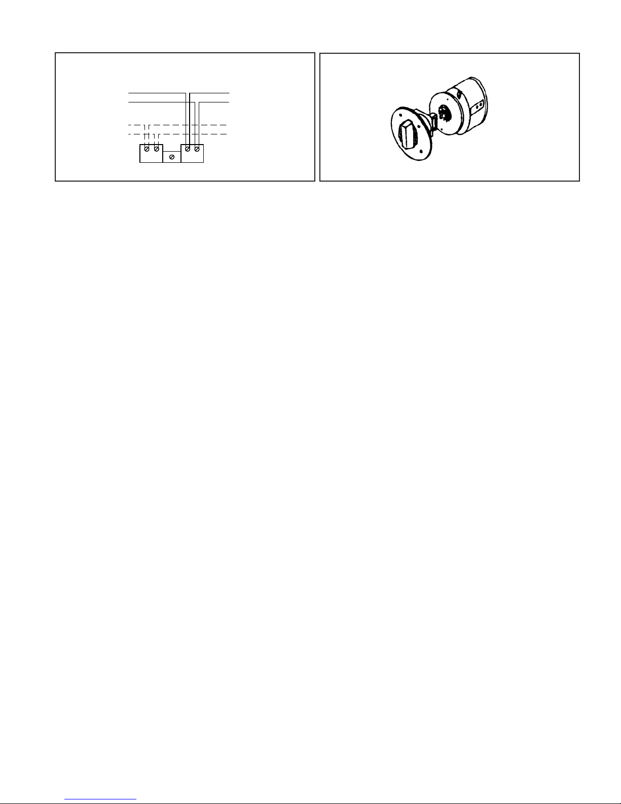
TheULC Listed“Rated InputVoltage”uses eitherfiltered (DC)or unfilteredfull-wave-rectified (FWR)voltage. Checkthe minimumand maximumoutput
ofthe power supplyand standbybatteryand subtract thevoltage drop from thecircuit wiringresistancetodetermine theapplied voltageto thestrobes.
Usethe highest valueof ratedaverage currentto determine themaximum numberof strobes andto establishpowersupplies and wire gaugerequire-
ments. Usetherated peakcurrent orrated inrushcurrent (whichever is higher) to verify fuse requirements.
Makesure thatthe average, peak and inrush currents donot exceedsystem power supplies or fusing limits. See “InstallationInstructions”.
WARNING: CONTACT WHEELOCK FOR “INSTALLATION INSTRUCTIONS” AND “GENERAL INFORMATION” SHEET ON THESE PRODUCTS.
THESE MATERIALS CONTAIN IMPORTANT INFORMATION THAT SHOULD BE READ PRIOR TO SPECIFYING OR INSTALLING THESE
PRODUCTS,INCLUDING:
• TOTAL CURRENT REQUIRED BYALLAPPLIANCES CONNECTED TO SYSTEM SECONDARY POWER SOURCES
• FUSE RATINGS ON NAC CIRCUITS TO HANDLE MAXIMUM INRUSH OR PEAK CURRENTS FROMALLAPPLIANCES ON THOSE NAC
CIRCUITS. THE TIME DURATION OF THE MAXIMUM STROBE INRUSH OR PEAK CURRENT IS 2 MILLISECONDS FOR LS
• INSTALLATION IN OFFICEAREASAND OTHER SPECIFICATIONAND INSTALLATION ISSUES
seireSrebmuNledoM redrO edoC ebortS alednaC ABdrekaepS teeF01ta
earevA 42@tnerruC *CDV
52srekaepSE SMRV
CLU-R-5207-E2874-
)09-18(
-
CLU-W-5207-E3494- -
CLU-W-5209-E4374- -
07srekaepSE SMRV
CLU-R-0707-E0424- -
CLU-W-0709-E9324- -
CLU-W-0707-E14
24- -
rekaepSE SMRV52sebortS
CLU-WFC-42-SL-5209-E23365147.0
CLU-RFV-42-SL-5207-E13365147.0
CLU-WFV-42-SL-5207-E8028514
7.0
rekaepSE SMRV07sebortS
CLU-WFC-42-SL-0709-E71365147.0
CLU-RFV-42-SL-0707-E61365147.0
CLU-WFV-42-SL-0707-E60775
147.0
Ordering Information
GeneralNotes:
• Strobes are designed tofalsh at 1 flash persecond minimum
• SeriesE SpeakerStrobesare Listed for indooruse witha temperaturerange of0°C to49°C (32°F to 120°F) and maximum humidityof 95%RH.
WARNING: USE STROBES ONLY ON NAC CIRCUITS WITH CONTINUOUSLYAPPLIED OPERATING VOLTAGE. DO NOT USE STROBES ON
CODED OR INTERRUPTED NAC CIRCUITS IN WHICH THEAPPLIED VOLTAGE IS CYCLED ON AND OFF,AS THE STROBE MAY NOT FLASH.
*AverageCurrentper actual WheelockProduction Testing @24 VDCnominal. For ratedaverage, peakand inrushacross the listed voltagerangefor
bothfiltered DCand full-wave-rectified(FWR), see installationinstructions.
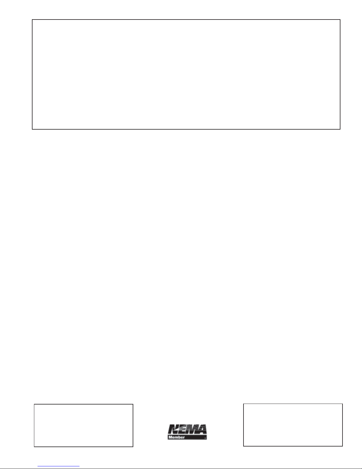
**Refer to Data Sheet #S7000 for mounting options. WARNING: SERIES E SPEAKERS DO NOT FITALL CANADIAN EXTENSION RINGS. Call
factoryfor assistance. (Exampleif ExtensionRing Manufacturerthat fitsisTEMCO).
SpeakerNotes: 1. Series E speakers have separate25 VRMS and 70 VRMS models. All Seires Emodels havefield selectable tapsfor 1/8,1/4, 1/2,1,
or2 watt operation. 2. Models code suffix V=verticallens; C=ceiling lens; F=fire lettering; R= red plate;W= white plate. 3. Approvalcodes: ULC=
UnderwriterLaboratoriesof Canada.
45

Wiring Diagrams
SERIES E SPEAKER & STROBE OPERATE
INDEPENDENTLY (NON-SYNC OR SYNC)
TO NEXT
APPLIANCE
OR EOLR
FROM
PRECEDING
APPLIANCE
OR VOICE
EVACUATION
PANEL TO NEXT
STROBE OR
EOLR
FROM
PRECEDING
STROBE, SYNC
MODULE, POWER
SUPPLY OR
FACP
SPEAKER
STROBE
+-+
+
-
-
-
++
+
-
-
Application Notes:
CAUTION: Checkthat theinstalledproduct willhave sufficientclearance and wiring room prior to installingbackboxes andconduit, especiallyif
sheathedmulticonductor cableor 3/4” conduit fittings areused.
1. Mountinghardwarefor each mountingoption issupplied.
2. Conduitentrancesto thebackbox should be selected toprovide sufficientwiring clearance for the installedproduct. Whenextension ringsare
required,conduit shouldenter throughthe backbox,not the extension ring. Note not all Canadian Extension Rings fit SeriesE. Call factory for
assistance.
3. Whenterminatingfield wires,do notuse morelead lengththan required. Excesslead lengthcould resultin insufficientwiring spaceforthe signaling
device.
4. Usecareand propertechniques toposition thefield wiresin thebackbox sothat theyuse minimumspaceand produceminimum stress on the
product. Thisis especiallyimportantfor stiff,heavy gaugewires andwires withthick insulationor sheathing.
5. Donotpassadditional wires(used forother thanthe signalingdevice) throughthe backbox. Such additional wires could result in insufficientwiring
spaceforthesignaling appliance.
6. Frequencyrangeof speakers is 400-4000 Hz.
7. Ablockingcapacitor for DC supervisionof audiolines bythe FACPis factorywired inseries with the speaker input 1.5uF for25 VRMS speakers
and0.15uF for70 VRMSspeakers.
CAUTION: Alwaysoperate audio amplifiers and speakerswithin theirspecified ratings. Excessive inputmay distortsound qualityand may damage
audioequipment. Do notexceed =130% ofspeaker ratedvoltage per CS 243. Improper inputvoltagecan damage speaker. If distortion isheard, check
forclipping ofthe audio signalwith anoscilloscope andreduce theamplifier input level or gainlevel toeliminate anyclipping.
Wheelockproductsmust be usedwithin their published specificationand must beproperly specified, applied, installed,operated,
maintainedandoperationally tested in accordancewith their installation instruction atthe time of installationand at leasttwice a yearor
moreoftenand in accordance withlocal, state,and federal codes, regulationsand laws. Specification,application, installation,
operation, maintenance and testingmust be performed by qualified personnelfor proper operation in accordancewith all of the latest
NationalFire ProtectionAssociation (NFPA), Underwriters’Laboratories(UL& ULC),local, state,county, province, district,federal and
otherapplicable building andfirestandards,guidelines, regulations, lawsand codes including, butnot limited toall appendicesand
amendmentsan the requirementsof local authorityhaving jurisdiction (AHJ).
Due to continuous development of our products, specifications and offering are subject to change without notice in accordance with
Wheelock, Inc. standard terms and conditions.
WARNING! PLEASE DO NOTE THAT THE E SERIES DO NOT FIT ALL CANADIAN EXTENSION RINGS.
CEILINGFLUSH MOUNTING
Circular Backbox for 4”
Speakeravailablein
Canadaonly By Others (BO)
Series
ET-1090
46

Architects and Engineers Specifications
The speaker appliance shall be a Wheelock Series E low profile speaker and speaker strobe appliance or equivalent.
The speaker and strobes shall be ULC Listed under CAN/ULC-S541-99 and CAN/ULC-S526-02 for Fire Protective
Service. All speakers shall be either 25 or 70 VRMS inputs with field selectable power taps from 1/8 to 2 watts with
Listed sound output up to 90 dBA at 10 feet, and a listed frequency response of 400 to 4000 Hz. Strobes shall use
filtered power or unfiltered power supply (full-wave-rectified). All models shall have provisions for standard reverse
polarity type supervision and IN/OUT field wiring using terminals that accept #12 to #18 AWG wiring.
Combination speaker strobe appliances signals shall incorporate a Xenon flashtube enclosed in a rugged Lexan lens
or equivalent with solid state circuitry. Strobe shall meet ULC and produce a flash rate of one (1) flash per second
minimum over the Listed input voltage range (20-31 VDC). The strobe intensity shall be rated per ULC for 15
candela. Thestrobe shallbecertified tomeetFCCPart15 ClassBand shallincorporatelow temperaturecompensation
to insure lowest possible current consumption.
The combination speaker strobe appliances shall be installed indoors and surface or flush mounted. They shall
mount to standard electrical hardware requiring no additional trimplate or adapter. The appliance shall be finished in
a textured red or white color.
WE ENCOURAGE AND SUPPORT NICET CERTIFICATION
3 YEAR WARRANTY
273 BranchportAvenue • Long Branch, NJ 07740 •TEL: 732-222-6880 •FAX: 732-222-2588
Distributed By:
National Sales Office
800-631-2148
Canada800-397-5777
E-Mail: [email protected]
http://www.wheelockinc.com
S1610C 02/05
ASSEMBLED IN THE USA
47
This manual suits for next models
5
Table of contents
Other Wheelock Smoke Alarm manuals
Popular Smoke Alarm manuals by other brands

BRK electronic
BRK electronic FG225 Manual Del Usuario

Polon-Alfa
Polon-Alfa DOT?4046 Installation and maintenance manual

VESDA
VESDA LaserPLUS Product guide

Fire Sentry
Fire Sentry SS4-A Installation and operation guide

SOMFY
SOMFY TaHoma 2401368 installation guide

System Sensor
System Sensor INNOVAIR DH100ACDCLWP Installation and maintenance instructions