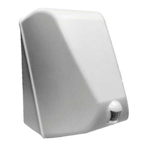
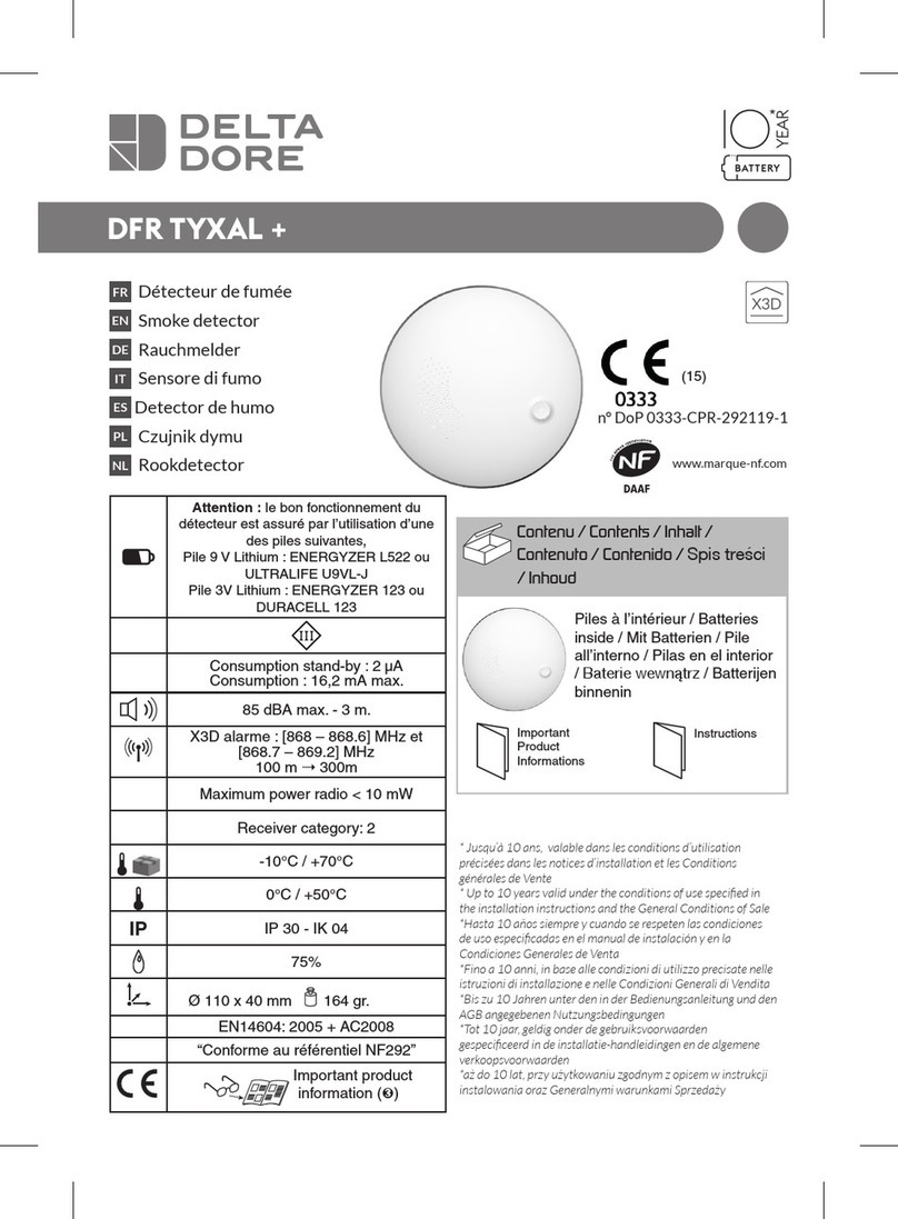
Smartek NUBI 4.0 NB40LP1 User manual

NB40LP1
REV 01 – Nov. 2018 - ENGLISH
NUBI 4.0
Model: NB40LP1
Power supply: L th um battery 3,6V
PIR: yes
Thank you for purchas ng NUBI 4.0, the ntell gent smoke
screen secur ty dev ce able to be connected to any burglar
alarm system n new or ex st ng systems.
OPERATIONAL OVERVIEW
The dev ce s powered by a 3.6V AA s ze l th um battery
suppl ed w th the product, such as SAFT LS14500 or
s m lar. Th s battery prov des the necessary energy to the
dev ce for a per od of 10 years. The gn t on of the smoke
cartr dge s ensured even when the battery s very low
(2.2V)
NUBI 4.0 eff c ently protects volumes up to 100 m3. The
smoke generated by NUBI 4.0 s based on ncense and
does not produce tox c atmosphere as tested accord ng to
the TLV-STEL d rect ve EU 2017/164 and ACGIH. After use
the room must be vent lated before stay ng there.
NUBI 4.0 s act vated through 3 nputs: one nput dr ves the
mmed ate em ss on of smoke, wh le the other two nputs
real ze a tr ple-consent log c to avo d false alarms. In th s
case, to tr gger the em ss on of smoke, t s necessary that
the state of the burglar system s armed, then w th n a t me
w ndow of 15 m nutes two other cond t ons occur:
1) The burglar system goes nto alarm
2) The ntegrated NUBI 4.0 PIR sensor detects movement
At the moment the second cond t on has been reach, the
smoke w ll be em tted mmed ately.
The nputs polar ty and log c level can be eas ly conf gured
us ng the DIP sw tches n order to nterface NUBI 4.0 w th
any burglar panel.
NUBI 4.0 has got two outputs to nform other dev ces
about alarm state and the battery low. The output log c
level can be reversed us ng DIP sw tches.
The box open ng s detected w th a tamper sw tch, ts clean
contact can be connected to the burglar panel.
An opt onal nternal s ren can be housed ns de the box
and plugged to the proper motherboard connector. In th s
case the dev ce must be powered by an aux l ary battery
pack, housed ns de the NUBI box and plugged nto the
appropr ate connector.
The smoke cartr dge works only once, the smoke
em ss on, when tr ggered, can no longer be nterrupted.
The smoke cartr dge replacement s very easy, each spare
cartr dge s prov ded w th a spec al board soldered on ts
w res to be eas ly plugged on the proper motherboard
connector.
INSTALLATION
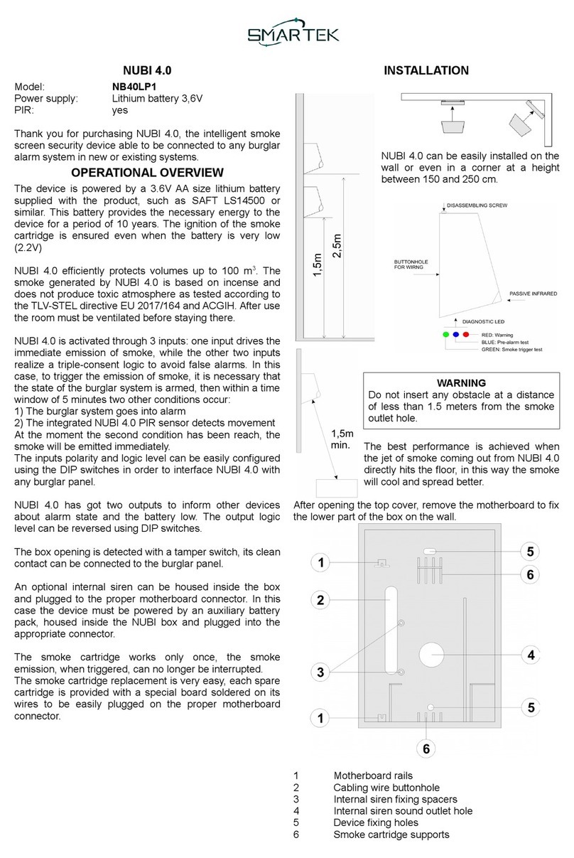
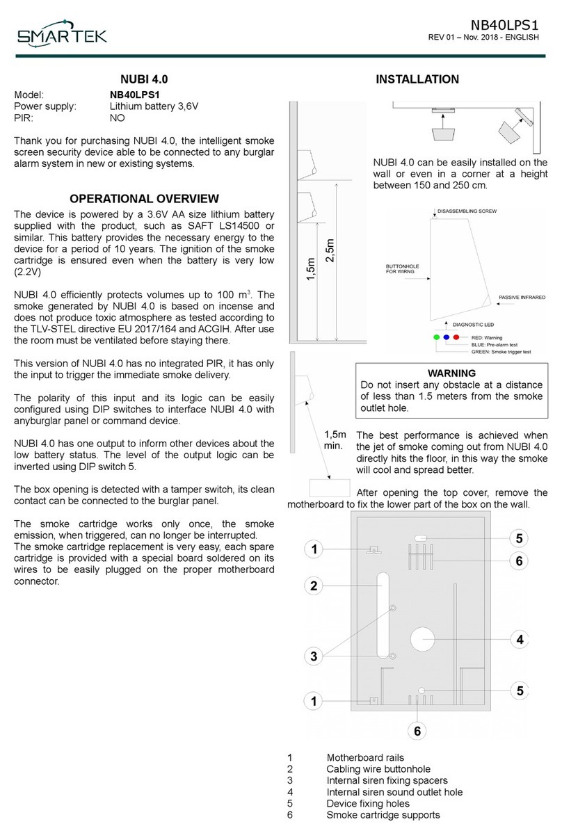
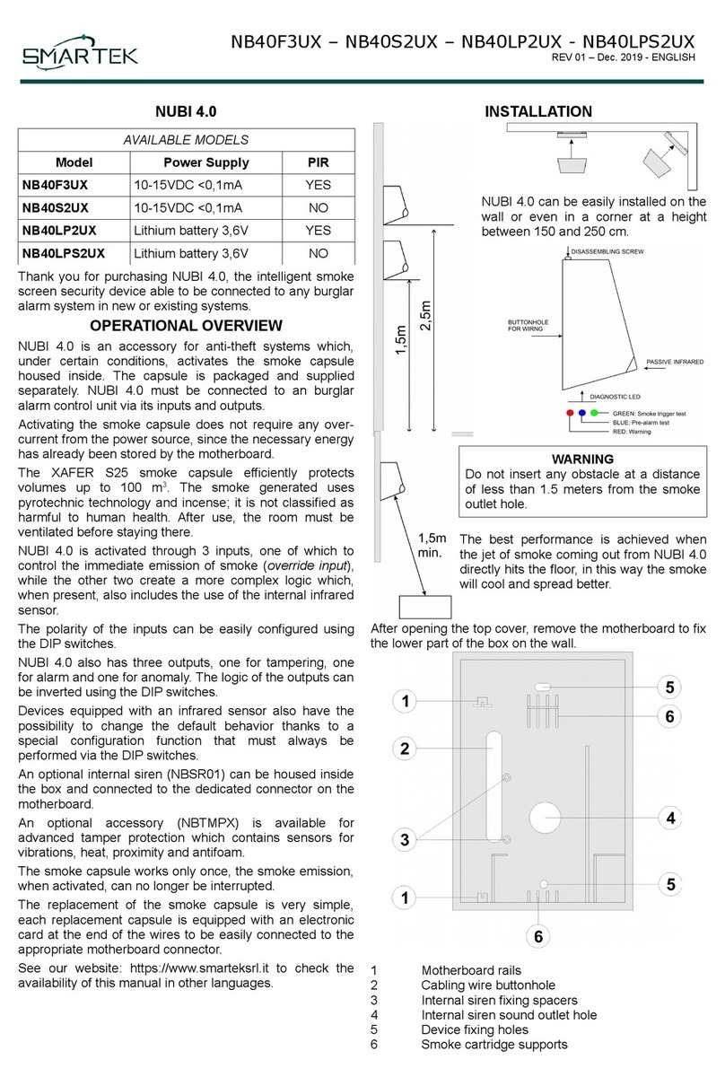
NUBI 4.0 can be eas ly nstalled on the
wall or even n a corner at a he ght
between 150 and 250 cm.
WARNING
Do not nsert any obstacle at a d stance
of less than 1.5 meters from the smoke
outlet hole.
The best performance s ach eved when
the jet of smoke com ng out from NUBI 4.0
d rectly h ts the floor, n th s way the smoke
w ll cool and spread better.
After open ng the top cover, remove the
motherboard to f x the lower part of the box on the wall.
1 Motherboard ra ls
2 Cabl ng w re buttonhole
3 Internal s ren f x ng spacers
4 Internal s ren sound outlet hole
5 Dev ce f x ng holes
6 Smoke cartr dge supports

NB40LP1
REV 01 – Nov. 2018 - ENGLISH
MAINBOARD
1) Ma n connector
2) Buzzer
3) D agnost c LEDs
4) PIR connector
5) Opt onal aux l ary battery pack
6) DIP Sw tch
7) Smoke cartr dge connector
8) Expans on bus connector
9) Internal s ren connector
10) Tamper sw tch
11) Val dat on board prov ded w th smoke cartr dge
12) Close th s Jumper when the motherboard s
powered w th external battery.
MAIN CONNECTOR
GND: Ground power supply
24H Tamper clear contact
+3V External power supply, nput or output.
CSI Immed ate smoke del very (INPUT)
SI System state (armed/d sarmed) (INPUT)
ALL Alarm (INPUT)
ALL Alarm (OUTPUT)
BL Battery low (OUTPUT)
+3V EXTERNAL POWER SUPPLY
Th s term nal takes the battery voltage of NUBI to power
an external dev ce or power the NUBI motherboard w th an
external battery nstead of the one suppl ed. In the f rst
case the Jumper (12) must be open and the battery l fe of
NUBI w ll be reduced due to the consumpt on of the
external dev ce. In the second case the jumper must be
closed and the supply voltage must not exceed 3.6V.
INPUTS INTERFACE
When the DIP Sw tches 1..4 are set to OFF, NUBI nputs
w ll become act ve when sw tched to GND, as shown n the
follow ng table:
CSI Tr gger the smoke del very when the nput s
closed to GND
SI Burglar system armed when the nput s closed to
GND, d sarmed when opened.
ALL Burglar alarm act ve when the nput s closed to
GND.
W th the DIP SW1 the nputs reference can be changed
from GND to VCC (3,6V). Us ng SW2, SW3, SW4 each
nput log c can be sw tched from normally open to normally
closed as shown the follow ng DIP Sw tches funct onal
table.
In the event that the nputs are not dr ven w th a clean
contact to GND, neve apply a voltage highe than
3.6V to the input wh ch would rrevers bly damage the
electron c c rcu t.
DIP SWITCHES
DIP OFF ON
1Input dr ven to GND Input dr ven to +3,6V
2CSI nput normally open CSI nput normally closed
3SI nput normally open SI nput normally closed
4ALL nput normally open ALL nput normally closed
5BL output act ve low BL output act ve open
6ALL output act ve low ALL output act ve open.
(Not for nternal s ren use)
7Operat ng mode Test mode
8Tamper enabled Tamper d sabled

NB40LP1
REV 01 – Nov. 2018 - ENGLISH
DIAGNOSTIC LEDs
D agnost c LEDs are act ve only n test mode.
BLUE NUBI pre-alarm n test mode.
GREEN Flash when the smoke cartr dge s tr ggered.
RED Warn ngs.
OUTPUTS
ALL output s act ve for 90 seconds start ng from the
beg nn ng of smoke del very. SW6 sets the output log c,
when use nternal s ren, set SW6 always to OFF.
BL output s act ve when the battery s low. SW5 sets the
output log c.
24H output s a clear contact normally closed when the
NUBI 4.0 box s closed, t w ll open when the box w ll be
opened. When the SW8 s set to ON, tamper output s
d sabled (output s always closed).
PIR RANGE
The p cture below shows the PIR range
TEST MODE
Set the DIP SW7 to ON to act vate the test mode. As soon
as the dev ce enters test mode, all the LEDs and the
buzzer w ll flash 8 t mes, then w ll be performed the battery
test:
•Green LED flash 3 t mes: full charge
•Green LED flash 2 t mes: med um charge.
•Green LED flash 1 t me: qu te low.
•RED LED + Buzzer: Battery must be replaced
When the battery s n good cond t on, the smoke cartr dge
w ll be tested, when t s empty the red LED and the buzzer
w ll l ght up and the green LED on the val dat on board w ll
be OFF. When the smoke cartr dge s not empty the green
LED on val dat on board w ll flash, the test w ll cont nue
and the BLUE led w ll flash slowly, one t me each second,
to nd cate the test mode s act vated. In test mode, each
t me the ntegrated PIR detect movement, the RED led w ll
flash and the buzzer w ll act vate for 1 second. When the
SI nput detects that the system s armed, one event
between the detect on of the PIR movement or the
act vat on of the ALL nput w ll cause the NUBI 4.0 pre-
alarm state for 15 m nutes and the blue LED w ll flash
qu ckly. When the second alarm event occurs w th n the
pre-alarm per od, the green LED w ll flash for 1 second to
nd cate the s mulat on of smoke del very.
If the pre-alarm was caused by the PIR detect on, the
alarm conf rmat on w ll be due to the act vat on of the ALL
nput. If the pre-alarm was caused by the act vat on of the
ALL nput, the conf rmat on w ll occur wh t the PIR
detect on. In test mode, the smoke cartr dge w ll never be
act vated and never the val dat on card w ll be damaged.
Remembe to activate the ope ating mode (DIP SW7
OFF) at the end of testing.
SMOKE CARTRIDGE REPLACEMENT
When a smoke cartr dge s empty, t must be replaced w th
a new one. The smoke cartr dge s suppl ed w th the
val dat on card welded to the ends of the w res. Only n test
mode (SW7 ON) the green LED on val dat on board w ll
flash when the cartr dge s full, OFF when t s empty and
needs to be replaced.
Remove the NUBI 4.0 batte y powe supply and wait
at least 3 minutes befo e eplacing the smoke
ca t idge.
1) Remove from the motherboard the old val dat on
card soldered onto the w res of the empty smoke
cartr dge.
2) Insert the new val dat on card soldered onto the
w res of the new cartr dge.
Commissioning
We adv se to perform a test (see prev ous chapter Test
mode) before perform a def n t ve comm ss on ng of the
dev ce. Set the DIP SW7 to OFF to sw tch n operat ng
mode. We adv se to remove the adhes ve that protects
smoke ex t hole of the smoke cartr dge.
WARNING PROCEDURE TO PREVENT SMOKE
EMISSION AT THE POWER UP
Dur ng the f rst 30 m nutes after power the dev ce, there
s a spec al funct on to prevent unwanted smoke
em ss ons, for example due to w r ng errors.
When the smoke act vat on cond t on occurs dur ng th s
t me, nstead of mmed ately em tt ng smoke, a warn ng
procedure starts and the buzzer em ts an nterm ttent
sound for 120 seconds and the red LED flashes.
It w ll be poss ble to stop the act vat on by open ng the
box and sett ng the DIP SW7 to ON or, n case of
d ff culty, t w ll also be poss ble to unplug the smoke
cartr dge val dat on card from the motherboard.
If th s warn ng procedure s not nterrupted, at the end of
the 120 seconds we w ll have the em ss on of smoke.
Each t me th s warn ng procedure s act vated, the 30-
m nute t mer s regenerated to allow an add t onal 30
m nutes of test t me.

NB40LP1
REV 01 – Nov. 2018 - ENGLISH
MAINTENANCE
We recommend replac ng the smoke capsule every 5
years us ng only the or g nal replacement.
WARRANTY
SMARTEK s.r.l. It guarantees ts products aga nst all
manufactur ng defects for a per od of 30 months from the
product on date shown on the label.
RECOMMENDATIONS
Before leav ng, vent late the rooms thoroughly after the
smoke has been del vered.
TECHNICAL SPECIFICATIONS
Power supply 3,6V l th um battery AA
s ze such as SAFT
LS14500 or s m lar
M n mum operat ng voltage 2,2V
Battery low output threshold 2,6V
Autonomy About 10 years
S ze 12cm x 17cm x 14cm
Saturable volume 100m3
We ght 760g
Smoke average del very t me 25sec
Operat ng temperature From 0°C to +45°C
Storage temperature From -20°C to +55°C
Max mum relat ve hum d ty 70%
Inputs SI – System state
ALL – Alarm
CSI – Immed ate act on
Outputs 24H – Tamper
ALL – Alarm
BL – Battery low
ADVANCED WIRING
The nputs nterface mode can be programmed us ng the
DIP sw tches SW1, SW2, SW3 and SW4 as prev ously
expla ned.
The nputs can be controlled not only w th clean contacts
but also w th open collector or push-pull outputs. The
mage below shows a typ cal NPN or PNP nterface.
For any k nd of nterface, the nputs voltage thresholds are
the followed:
M n V Max V
Level 0 GND 0,5V
Level 1 1,9V +Vbatt
WORKING DIAGRAM
Other Smartek Smoke Alarm manuals
Popular Smoke Alarm manuals by other brands

AJAX
AJAX FireProtect user manual
Pittway
Pittway System Sensor B524BI Installation and maintenance instructions
DSC
DSC WLS916-433 Series Installation and operating instructions

First Alert
First Alert SA320CN-2 quick start guide

Bosch
Bosch D285DH installation instructions
Bellman & Symfon
Bellman & Symfon BE1287 user manual
DSC
DSC Maxsys PC4612 installation instructions

nest
nest PROTECT user guide

Panasonic
Panasonic 1826 Specification sheet
Ei Electronics
Ei Electronics EI 100B Standard Instruction leaflet
System Sensor
System Sensor Innovair flex 2D51 Installation and maintenance instructions
Kidde
Kidde 1276E Brochure & specs
