Before testing, notify the proper authorities that the
system is undergoing maintenance, and will temporarily
be out of service. Disable the system to prevent unwanted
All sensors must be tested after installation and
periodically thereafter. Testing methods must satisfy the
Authority Having Jurisdiction (AHJ). Sensors offer
maximum performance when tested and maintained in
The sensor can be tested in the following ways:
A. Smoke Entry test: Aerosol Generator (Gemini 501)
The GEMINI model 501 aerosol generator can be used
for smoke entry testing. Set the generator to represent
4%/ft to 5%/ft obscuration as described in the GEMINI
501 manual. Using the bowl shaped applicator, apply
aerosol until the panel alarms. Additionally, canned
aerosol simulated smoke (canned smoke agent) may be
used for smoke entry testing of the smoke detector. Tested
and approved aerosol smoke products are the Smoke
Detector Tester model 25S available from Home
Safeguard Industries and Chekkit Smoke Detector Tester
models CHEK02 and CHEK06 available from SDi.
When used properly, the canned smoke agent will cause
the smoke detector to go into alarm. Refer to the
manufacturer’s published instructions for proper use of
A.Canned aerosol simulated smoke (canned smoke agent)
formulas will vary by manufacturer. Misuse or overuse of
these products may have long term adverse effects on the
smoke detector. Consult the canned smoke agent
manufacturer’s published instructions for any further
warnings or caution statements.
B. Direct Heat Method (Hair Dryer of 1000-1500 watts)
A hair dryer of 1000-1500 watts should be used to test the
thermistors. Direct the heat toward either of the two
thermistors, holding the heat source approximately 12
inches from the detector in order to avoid damaging the
plastic housing. The detector will reset only after it has
had sufficient time to cool. Make sure both thermistors
A sensor that fails any of these tests should be cleaned as
described under CLEANING, and retested. If the sensor
fails after cleaning, it must be replaced.
When testing is complete, restore the system to normal
operation and notify the proper authorities that the system
Before removing the detector, notify the proper
authorities that the smoke detector system is undergoing
maintenance and will be temporarily out of service.
Disable the zone or system undergoing maintenance to
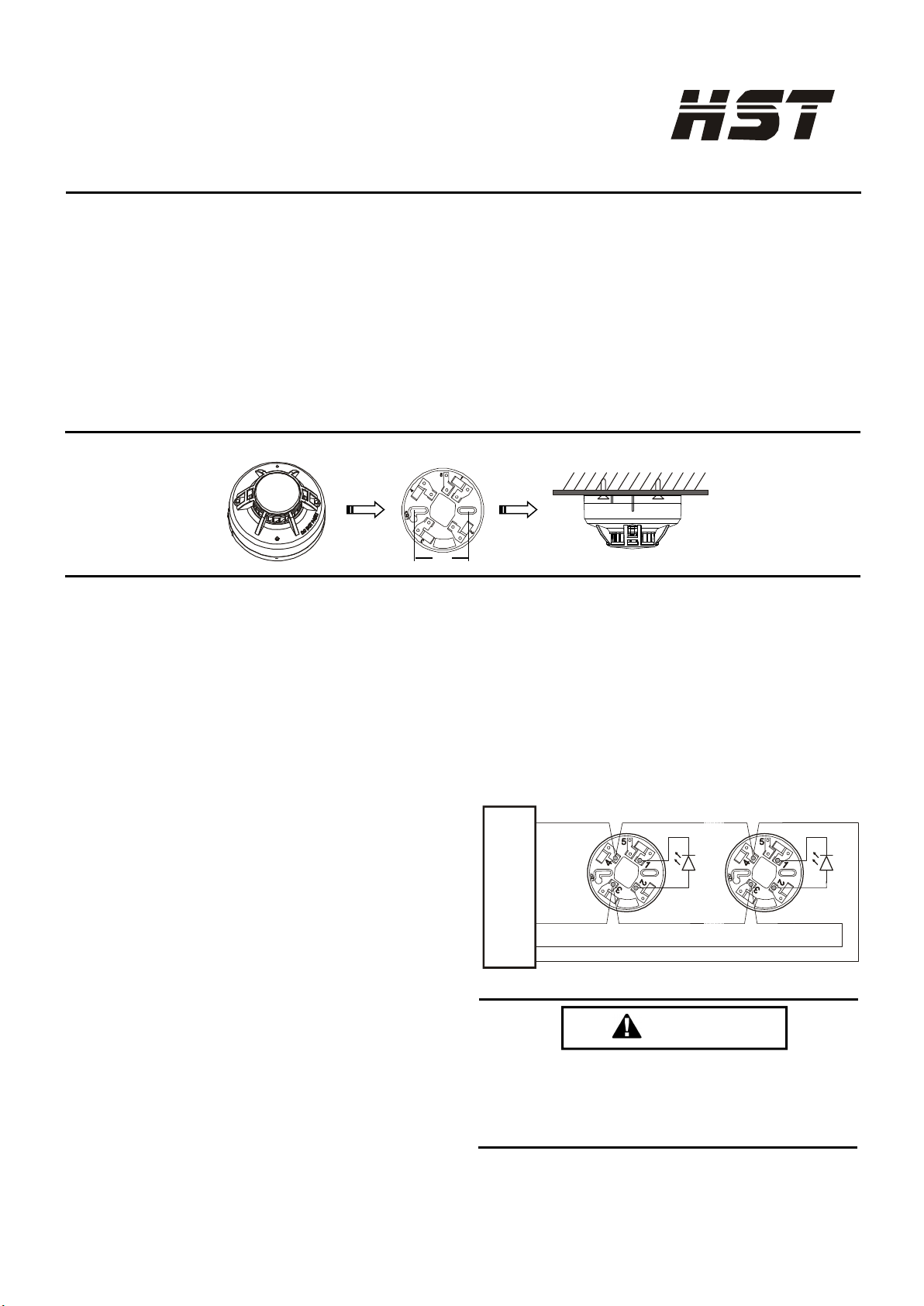
1. Remove the sensor to be cleaned from the system.
2. Remove the sensor cover by pressing firmly on each
of the four removal tabs that hold the cover in place.
3. Vacuum the screen carefully without removing it. If
further cleaning is required continue with Step 4,
otherwise skip to Step 7.
4. Remove the chamber cover/screen assembly by
5. Use a vacuum cleaner or compressed air to remove
dust and debris from the sensing chamber.
6. Reinstall the chamber cover/screen assembly by
sliding the edge over the sensing chamber. Turn until
7. Replace the cover using the LEDs to align the cover
and then gently pushing it until it locks into place.
8. Reinstall the detector.
9. Test the detector as described in TESTING.
10. Reconnect disabled circuits.
11. Notify the proper authorities that the system is back
THREE-YEAR LIMITED WARRANTY
We warrants its enclosed smoke detector to be free from defects in materials and workmanship under normal use and service for a period of three years from date of
manufacture. We makes no other express warranty for this smoke detector. No agent, representative, dealer, or employee of the Company has the authority to increase or
alter the obligations or limitations of this Warranty. The Company’s obligation of this Warranty shall be limited to the repair or replacement of any part of the smoke
detector which is found to be defective in materials or workmanship under normal use and service during the three year period commencing with the date of manufacture.
After phoning Convoy Security’s technical support number for a Return Authorization number, send defective units postage prepaid to Convoy Security local
representative office. Please include a note describing the malfunction and suspected cause of failure. The Company shall not be obligated to repair or replace units which
are found to be defective because of damage, unreasonable use, modifications, or alterations occurring after the date of manufacture. In no case shall the Company be
liable for any consequential or incidental damages for breach of this or any other Warranty, expressed or implied whatsoever, even if the loss or damage is caused by the
Company’s negligence or fault. Some states do not allow the exclusion or limitation of incidental or consequential damages, so the above limitation or exclusion may not
apply to you. This Warranty gives you specific legal rights, and you may also have other rights which vary from state to state.
FCC STATEMENT
This device complies with part 15 of the FCC Rules. Operation is subject to the following two conditions: (1) This device may not cause harmful interference, and (2)
this device must accept any interference received, including interference that may cause undesired operation.
NOTE: This equipment has been tested and found to comply with the limits for a Class B digital device, pursuant to Part 15 of the FCC Rules. These limits are designed
to provide reasonable protection against harmful interference in a residential installation. This equipment generates, uses and can radiate radio frequency energy and,
if not installed and used in accordance with the instructions, may cause harmful interference to radio communications. However, there is no guarantee that interference
will not occur in a particular installation. If this equipment does cause Harmful interference to radio or television reception, which can be determined by turning the
equipment off and on, the user is encouraged to try to correct the interference by one or more of the following measures:
–Reorient or relocate the receiving antenna.
–Increase the separation between the equipment and receiver.
–Connect the equipment into an outlet on a circuit different from that to which the receiver is connected.
Please refer to insert for the Limitations of Fire Alarm Systems