Smartinterface Lunette User manual

1
Rev. 2 . 0 .1 www.smartinterface.de · info@smartinterface.de
Instructions – Lunette Wrench Set
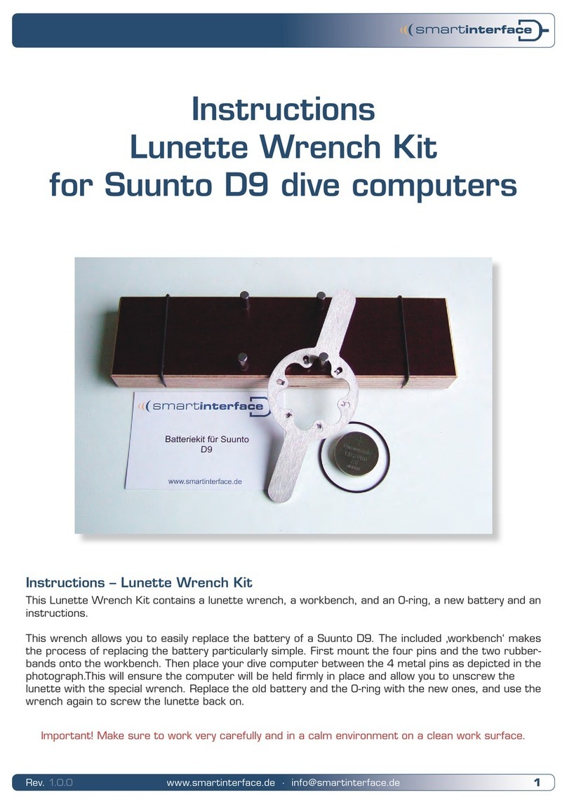
The Lunette wrench Set consists of the lunette wrench, a workbench, a pin and an O-ring, as well as a
battery.
This wrench allows you to replace the battery of a Suunto Stinger or a Spyder in a simple do-it-yourself
process. The included workbench greatly facilitates the process of replacing the battery. Place your
diving computer between the 4 metal pins as depicted in the bottom illustration (photograph).
This will ensure that the computer remains securely fastened in place, thus allowing you to unscrew the
crown with the special wrench. Replace the old battery and the O-ring with the new ones, and use the
wrench again to screw the crown back on.
Important! Make sure to work very carefully (and in a calm environment)
on a clean work surface. Use pin as assembly tool.
Instructions
Lunette Wrench Set

2
Rev. 2 . 0 .1 www.smartinterface.de · info@smartinterface.de
1.0 Place clock on workbench (90° to workbench)
2.0 Place wrench onto lunette. (cogs must grip, level)
Lunette Wrench Set

3
Rev. 2 . 0 .1 www.smartinterface.de · info@smartinterface.de
2 .1 Turn wrench to the left (lunette fits very tight)
2.2 Unscrew lunette by hand.
Lunette Wrench Set

4
Rev. 2 . 0 .1 www.smartinterface.de · info@smartinterface.de
2.3 Place lunette aside
3.0 Use pin to lift the glass on the side containing the small notch.
Lunette Wrench Set

5
Rev. 2 . 0 .1 www.smartinterface.de · info@smartinterface.de
3 .1 Place glass aside
4.0 Lift synthetic ring with the pin.
Lunette Wrench Set

6
Rev. 2 . 0 .1 www.smartinterface.de · info@smartinterface.de
4 .1 Place synthetic ring aside.
5.0 Lift O-ring with the pin.
Lunette Wrench Set

7
Rev. 2 . 0 .1 www.smartinterface.de · info@smartinterface.de
5 .1 Remove and discard the O-ring (NOT intended for re-use).
6.0 Carefully extract clock element (ease element out by holding on at the top and the bottom!)
Lunette Wrench Set

8
Rev. 2 . 0 .1 www.smartinterface.de · info@smartinterface.de
6 .1 Remove clock element (watch out for the wire) und place it upside down into the casing.
7. 0 Lift battery clamp (star) by the protruding point.
Lunette Wrench Set

9
Rev. 2 . 0 .1 www.smartinterface.de · info@smartinterface.de
7.1 Place battery clamp (star) aside.
8.0 Remove battery (carefully extracting it with the pin) and properly dispose of the battery.
Lunette Wrench Set

10
Rev. 2 . 0 .1 www.smartinterface.de · info@smartinterface.de
8 .1 Do not throw battery into trash; use public collection facilities for hazardous materials.
8.2 Insert new battery.
Lunette Wrench Set

11
Rev. 2 . 0 .1 www.smartinterface.de · info@smartinterface.de
9.0 Place battery clamp back on unit (hooking in the left side first).
9 .1 Place battery clamp back on unit (pushing right side down with pin).
Lunette Wrench Set

12
Rev. 2 . 0 .1 www.smartinterface.de · info@smartinterface.de
10.0 Turn clock element back around (watch out for the wire) and insert.
10 .1 Press clock element into casing (don’t push on the display – only on the edge).
Lunette Wrench Set

13
Rev. 2 . 0 .1 www.smartinterface.de · info@smartinterface.de
10.2 Press clock element into casing (don’t push on the display – only on the edge).
11.0 Insert new O-ring exactly into the surrounding groove. (The O-ring must be free of grease!)
Lunette Wrench Set

14
Rev. 2 . 0 .1 www.smartinterface.de · info@smartinterface.de
12.0 Place synthetic ring back on unit (check the fit of the O-ring).
13.0 Put glass back on unit (with the larger surface facing downward).
Clean glass prior to this to avoid fingerprints on the glass.
Lunette Wrench Set

15
Rev. 2 . 0 .1 www.smartinterface.de · info@smartinterface.de
14.0 Place lunette back on unit (check for level fit).
14 .1 Wind lunette forward by hand (check for level fit).
Lunette Wrench Set

16
Rev. 2 . 0 .1 www.smartinterface.de · info@smartinterface.de
14.2 Place wrench onto lunette (Mesh must grip, be level).
14.3 Tightly fasten lunette with lunette wrench.
Lunette Wrench Set

17
Rev. 2 . 0 .1 www.smartinterface.de · info@smartinterface.de
Index of Contents
1.0 Place clock on workbench (90° to workbench) 2
2.0 Place wrench onto lunette. (cogs must grip, level) 2
2 .1 Turn wrench to the left (lunette fits very tight) 3
2.2 Unscrew lunette by hand. 3
2.3 Place lunette aside 4
3.0 Use pin to lift the glass on the side containing the small notch. 4
3 .1 Place glass aside 5
4.0 Lift synthetic ring with the pin. 5
4 .1 Place synthetic ring aside. 6
5.0 Lift O-ring with the pin. 6
5 .1 Remove and discard the O-ring (NOT intended for re-use). 7
6.0 Carefully extract clock element (ease element out by holding on at the top and the bottom!) 7
6 .1 Remove clock element (watch out for the wire) und place it upside down into the casing. 8
7. 0 Lift battery clamp (star) by the protruding point. 8
7.1 Place battery clamp (star) aside. 9
8.0 Remove battery (carefully extracting it with the pin) and properly dispose of the battery. 9
8 .1 Do not throw battery into trash; use public collection facilities for hazardous materials. 10
8.2 Insert new battery. 10
9.0 Place battery clamp back on unit (hooking in the left side first). 11
9 .1 Place battery clamp back on unit (pushing right side down with pin). 11
10.0 Turn clock element back around (watch out for the wire) and insert. 12
10 .1 Press clock element into casing (don’t push on the display – only on the edge). 12
10.2 Press clock element into casing (don’t push on the display – only on the edge). 13
11.0 Insert new O-ring exactly into the surrounding groove. (The O-ring must be free of grease!) 13
12.0 Place synthetic ring back on unit (check the fit of the O-ring). 14
13.0 Put glass back on unit (with the larger surface facing downward).
Clean glass prior to this to avoid fingerprints on the glass. 14
14.0 Place lunette back on unit (check for level fit). 15
14 .1 Wind lunette forward by hand (check for level fit). 15
14.2 Place wrench onto lunette (Mesh must grip, be level). 16
14.3 Tightly fasten lunette with lunette wrench. 16

19
Rev. 2 . 0 .1 www.smartinterface.de · info@smartinterface.de
WEEE-Reg.-Nr. DE82497460
Technisches Büro Kühnhold
Ehestorfer Weg 155
21075 Hamburg · Germany
http://www.smartinterface.de · info@smartinterface.de
All images and text in this instruction manual, as well as the instruction
manual itself are copyright protected, any further use must be appro-
ved in writing by www.smartinterface.de.
All brands and trademarks specified within the description and, where
applicable, protected by a third party are subject without restriction to
the terms and conditions of the respectively valid right to use a symbol
and the ownership rights of each registered owner. The mere mention
thereof shall not be construed to represent that the trademarks are
not protected by third party rights! The brand names and trademarks
used in this documentation are the property of the respective rights
owners and are used here only for descriptive purposes.
Opening the dive computer and replacing the battery shall be at your
own risk! No liability shall be assumed for lack of waterproofness or
damage.
European Union – Disposal information: This symbol indicates that this
product must be disposed of pursuant the valid legal provisions and
separated from domestic waste.
Bring this product to an official collection point for disposal. Products
can be brought to some collection points for disposal free of charge.
Separate collection and recycling conserves raw material reserves and
ensures compliance with all regulations for the protection of health
and the environment when recycling the product.
Publisher
Copyright
Copyright and labeling
Disclaimer
Recycling
Other Smartinterface Power Tools manuals
Popular Power Tools manuals by other brands
Hellermann Tyton
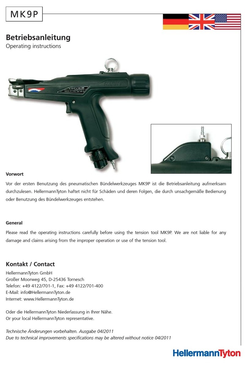
Hellermann Tyton MK9P operating instructions

Delta
Delta E Series Installation and maintenance instructions
Delta
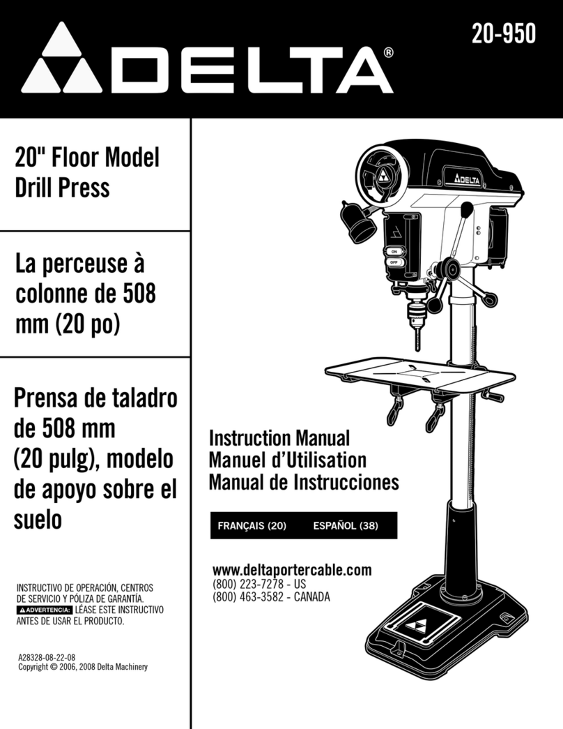
Delta 20-950 instruction manual

MasterForce
MasterForce 69MF1096 manual
Central Pneumatic
Central Pneumatic 66874 Set up and operating instructions

Band-it
Band-it G40269 Giant II operating instructions

CO/Tech
CO/Tech TD8503T-UK Original instructions

OEM Tools
OEM Tools 24494 Operating instructions and parts manual

OEM Tools
OEM Tools 24815 Operating instructions and parts manual
Power Fist
Power Fist 9093899 manual

Thomas&Betts
Thomas&Betts BCT840 INSTALLATION AND GAUGING PROCEDURE

Chef's Choice
Chef's Choice Ceramic + Steel 700 instructions
