2
Operating Instructions and Parts Manual 24815
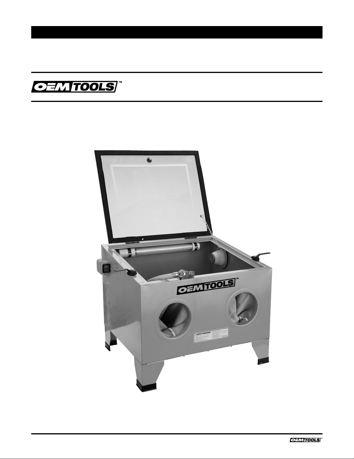
SANDBLAST BENCH TOP CABINET
5/19
2019 OEMTOOLS™
Thank you for purchasing this OEM Shot Blast Cabinet
which is designed for professional, workshop use.
LIMITED 90 DAY WARRANTY
If within 90 days from date of purchase, this product fails due to
a defect in materials or workmanship, return the product
with proof of purchase, prepaid, to OEM Warranty Dept., 3580
E. Raines Rd. #3, Memphis, TN 38118, for repair or replace-
ment with an item of equal or greater value. This warranty
excludes incidental/consequential damages and failures due to
misuse, abuse or normal wear and tear. This warranty gives you
specific legal rights, and you may also have other rights, which
vary, from state to state. OEM will not be responsible for any
consequential or incidental damages arising from the breach
of this or any other warranty, whether expressed, implied or
statutory. Some states do not allow the exclusion or limitation
of consequential or incidental damages, so the above exclusion
may not apply to you. This warranty gives you specific legal
rights, and you may also have other rights which vary from
state to state.
ALWAYS WEAR SAFETY GOGGLES.
CONTENTS Page
Spare Parts & Service Contents ............................... 1
Features .................................................................... 2
Safety Precautions .................................................... 2
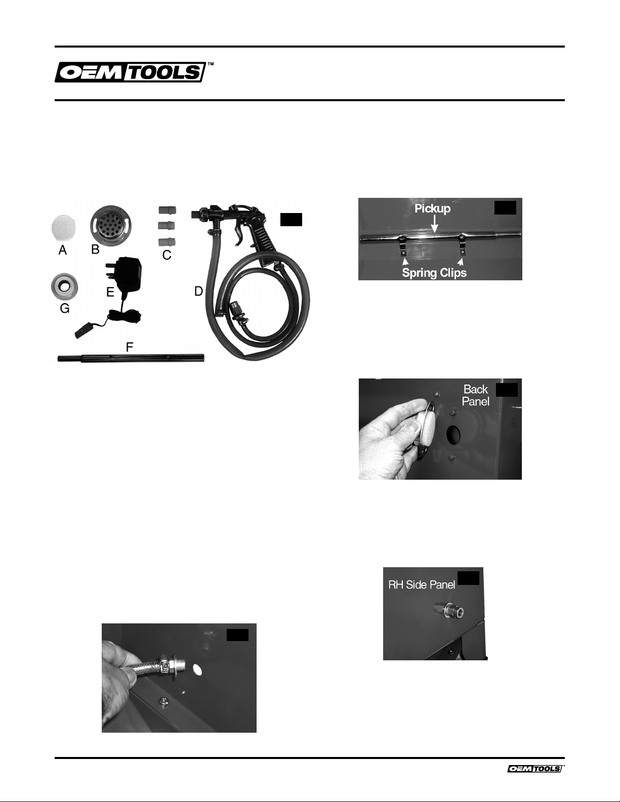
Assembly................................................................... 3
Changing Nozzles .................................................... 4
Operation .................................................................. 4
Maintenance ............................................................. 5
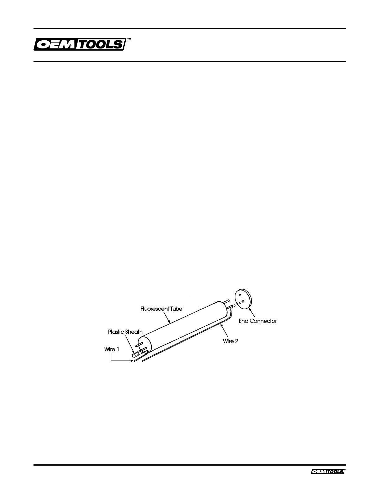
Changing the Fluorescent Tube ............................... 5
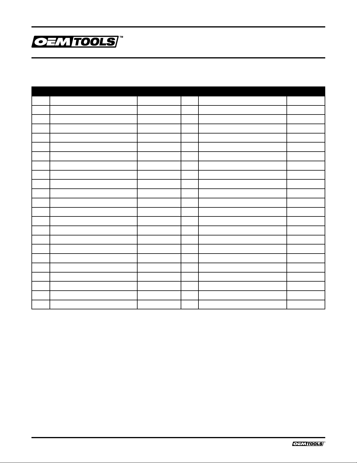
Parts Diagrams ......................................................... 6
Parts List .................................................................. 7
Troubleshooting ........................................................ 8
FEATURES
The 3 cu. ft. cabinet is lit by a low voltage (12 volt)
fluorescent tube. A transformer is provided which
should be plugged directly into the main supply. The
attached cable is then plugged into the switch box,
mounted on the left side of the cabinet. The switch box
contains the ON/OFF rocker switch.
We strongly recommend that this unit be used with a
vacuum extraction device. Air is extracted via a double
filtration system from the facility at the right hand side
of the cabinet.
Please note that when vacuum extraction is used,
air will be drawn into the cabinet through the hole on
the back panel of the unit. The hole is covered on the
outside with a filter plate, and housed within the plate
is a foam filter, which must always be in place. This
is to prevent grit from being blown out, if/when the
vacuum extraction is NOT used.
The lid is provided with a double clear plastic window,
the inner of which may be renewed quickly and easily if it
should become damaged by the sand blasting action.
A variety of abrasive nozzles is supplied with the unit
to produce a useful range of power and grit densities
to satisfy all requirements. The cabinet is designed
for use with dry abrasives ONLY. We recommend
Aluminium Oxide (for cleaning steel) and Glass Beads
(for cleaning Aluminium).
It is necessary to provide a clean, dry air supply,
capable of delivering a minimum of 10 cu. ft./min at
100 PSI. Please consult your air compressor manual,
ensuring you comply with all safety precautions
regarding the use of air compressors, and observe all
necessary precautions when using compressed air.
SAFETY PRECAUTIONS
• Ensure you comply with all precautions concerning
the use of air compressors and compressed air.
• Ensure all air connections are secure.
• Do Not use the machine if the rubber gloves are
ripped or otherwise unserviceable.
• Ensure the clear plastic lid is firmly secured before
pressing the trigger.
• Keep the jet well away from the air inlet hose (from
side panel to gun).
• ALWAYS wear safety glasses. (Normal eye glasses
are NOT safety glasses).
WARNING:This product can expose you to
chemicals, including DEHP and lead, which are
known to the State of California to cause cancer and
birth defects or other reproductive harm. For more
information, go to www.P65Warnings.ca.gov.