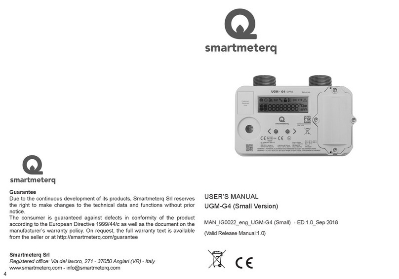
Smartmeterq UGM-G4 Operating instructions

UGM-G4 (Ultrasonic Gas Meter)
USER AND MAINTENANCE
MAN_IG0002_eng_UGM-G4 (Ultrasonic Gas Meter) - ED.1.0_Feb 2019
(Valid Release Manual:1.0)
Index
1 Introduction 3
2 Safety Instructions 3
2.1 ATEX 4
2.2 Electrostatic discharge (ESD) 5
2.3 Environment 5
2.4 Transport and storage 5
2.5 Batteries replacement 6
3 User Interface 6
3.1 Keypad 6
3.2 Display 6
3.2.1 Icons 7
3.3 MENU 7
4 Installation 7
4.1 Mechanical installation 7
4.2 Meter activation 9
4.2.1 Meter activation with meter user interface 9
4.2.2 Meter activation with meter optical port 9
4.3 Data transmission 10
5 Communications 10
5.1 Local communication 10
5.2 Remote communication 11
6 Maintenance 12
6.1 Ordinary maintenance 12
6.1.1 Battery replacement 12

3
UGM G4 (Ultrasonic Gas Meter) is a gas smart meter for domestic use. Its main
application is at the end point of delivery of natural gas network. It is suitable
also for use in LPG gas network. The device integrates an electronic ultrasonic
sensor able to measure the gas volume at standard condition (compensation
in temperature). It is equipped with an optical port for local communication and
a communication module for remote communication. Remote communication
allows the AMR (Automatic Meter Reading) services and the remote control
of the gas supply. The communication protocol used for local and remote
communications is DLMS/COSEM protocol. UGM meter is used in low
pressure measuring systems (< 0.5 bar) with ow less than 6 m3/h (A2 class,
according to the classication of UNI/TS 11291 norm).
1. Introduction
UGM meter is available in different models with the following common main
features:
• ultrasonic sensor;
• integrated temperature sensor;
• electro-valve to stop the gas supply;
•2 not-rechargeable batteries (metrological battery and communication
battery);
• optical port for local communication (compliant to IEC 62056-21 norm);
• integrated GSM module for remote communication ;
• LCD display (user interface);
• 2 push buttons (user interface);
• anti-fraud tamper switch.
The different meter UGM models differ in the following features:
•communication module type/model (GPRS, UMTS, NB-IoT, LTE Cat M1);
• meter size (G4) ;
•meter case (small, large) ;
•pitch pipe (100, 110, 152, 220, 250 mm)
•connection pipe (3/4”, 1”, 1 1/4”)
2. Safety Instructions
Observe the following Safety Instructions to ensure that neither persons or gas
meters are damaged during installation and operation
• Install device in the right orientation position (vertical).
•Install device in a compartment that complies with the applicable legal
requirements about security.
•Install device far from any damages originating by mechanical shock, heat
source or ame, i.e. place device in dry place protect against weathering.
• Do not scratch or rub during installation and use.
•Do not remove or damage metrological seals, if not authorized.
•The device must be installed only by an authorized installer, compliant to
the applicable legal requirements about security.
• Every technical change on the device is forbidden.
• Respect the construction parameter and security warnings.
•When tightening the tting not overcome the 110 Nm torque.
• Install the gas meter free of mechanical stress.
•Maximum pressure of the plant has to be lower than the maximum
pressure allowed for the meter (0.5 bar relative pressure).
•Relieve internal pressure completely before removing the device. Ensure
proper ventilation because of possible escapes of residual gas. Cap the
inlet/outlet connections.
• Do not install the meter if it is damaged.
•The integrated valve of the gas meter does not assumes the functions of
a safety shut-off valve.
•Before to connect to the plant be sure that the customer’s consumers are
closed.
•Before to connect to the plant be sure that the security shut-off valve
upstream the meter is closed, so there is no gas ow during installation.
•Any necessary meter pipe work, soldering, drilling or other installation
works must be completed before the meter is unboxed, uncapped and
tted.
SmartMeterQ disclaims all liabilities from the risks and
consequences of non-compliance with these prescriptions.
The following important safety instructions have to be ensured:
•All national rules for installation, operation, inspection and maintenance of
gas meters must be respected.
•If there is a risk of internal or external corrosion, inspect the device
regularly. If the device is clearly affected by corrosion, put it out of use.
•The operating conditions indicated on the meter front panel, especially
maximum admissible operation pressure and ow rate, have to be
respected. The device is not designed to withstand earthquakes and
oods.
2.1 ATEX
UGM meter is suitable for use in low risk atmosphere explosive area (risk only
for short period).
UGM meter is an intrinsically safe apparatus complies to the directive for
atmosphere explosive 2014/34/EU. It is suitable for installation in zone 2, gas
group IIB, category II 3G.
The UGM meter ATEX marking is: II 3G Ex ic IIB T3 Gc
4

2.2 Electrostatic discharge (ESD)
Area of installation is classied as “low ATEX risk”, but the spark ignition due to
ESD (electrostatic discharge) could cause explosions. Due to this reason, it is
recommended during manual operation of installation/maintenance:
• Use dissipative boots.
• Use damp cloth (% > 65%).
During installation and use, it is recommended to adopt all
precautions to protect the meter against electrostatic discharge.
2.3 Environment
For the environment of installation, the following instructions have to be
considered.
• Operating temperature range: -25°C to +55°C.
•The meter can be installed in indoor or outdoor location (degree of
protection: IP55).
•In indoor installation it is recommended to install the meter a suitably
ventilated area.
•In outdoor installation it is recommended to install the meter in a location
protected from direct sun light and weathering (use a shed or a cover or
use a niche in the wall).
•The meter may be installed indoors in a suitably ventilated area or in
an outdoor meter box constructed for the installation of Gas meters and
compliant with the requirements of BS6400, provided that the door is tted
to the box and is kept closed at all times, excepting when interaction with
the meter is necessary.
2.4 Transport and storage
For transport and storage, the following instructions have to be considered.
• Store the meter in dry place in vertical position.
• Storage temperature range of -25° to +55°C has to be ensured.
• Handle gas meters with care during transport. Shock must be avoided.
•Always keep the meter in vertical position during transport and installation.
•On receipt, carefully examine the shipping container and the meter itself
for any external damage. Any visible damage should be reported to the
carrier.
•Before installation, the meter must be checked for possible damage.
Never install a damaged meter.
•Do not remove the 2 protective caps tted at the inlet and outlet connections
during transport and storage. The caps must stay in place until installation.
2.5 Batteries replacement
For battery replacement, the following instructions have to be considered.
•Use only homologate batteries provided by SmartMeterQ. Other types of
batteries are not allowed.
• Do not change the batteries when an atmosphere explosive is present
•Every intervention on the batteries must be performed only by an
authorized installer.
• Batteries have to be disposed according the national rules.
3 User Interface
User interface comprises 2 push buttons and the display.
Following paragraphs explains how to access to display user interface and the
means of every icons and symbol shown by screen of display.
3.1 Keypad
Two buttons are available for menu navigation:
• Push button 1 - LEFT button
• Push button 2 - RIGHT button .
3.2 Display
Display is divided in 4 areas (see gure below):
• Icons
•Identication menu (2 alphanumeric characters, complied to standard
UNI/TS 11291-6)
• Data value (8 alphanumeric characters)
• Measurement units.
Fig.1 Display
56

Icon Description
Log Data view refers to previous billing period
Clock
Data view refers to date and time
Date: ID menu letter “D”
Time: ID menu letter “H”
RF Field Icon On: GSM or radio module on
Icon Off: GSM or radio module in low power
Mailbox
0.5Hz ashing means an user message is available for reading.
User enter on screen with ID menù: “MU” and watch the message (Mailbox icon
xed on) after user leave screen with ID “MU” Mailbox icon switch off.
Key service Entered in Maintenance/test menù.
ID Menù: “DG” (diagnosis)
Lock Authentication required to access to this screen.
Lock icon switch off if authentication success.
Money Data view refers to Credit (only prepaid devices)
Valve
Valve status
Icon On: valve close
Con Off: valve open
ID menù “SV”, state of valve reported into 8 alphanumeric characters (A, C, R see
valve code)
Battery Battery level low (residual battery charge < 10%)
3.2.1 Icons
3.3 MENU
With the display off, press LEFT or RIGHT button and keep it press for 3
seconds. Display turns on and shows the rst screen. To navigate into the
menu, press LEFT button or RIGHT button to scroll the different menu items.
4. Installation
UGM G4 meter installation is composed by 3 phases:
1. mechanical Installation;
2. meter activation;
3. data transmission.
Data transmission phase is optional.
4.1 Mechanical installation
UGM G4 meter is provided with the two batteries electrically connected and the
valve in “open” status.
Attention - Read and verify the safety instructions reported in
the “Safety Instructions” chapter of this manual before starting
the meter installation.
Connection to the gas pipes
• The UGM G4 meter must only be installed with the occupier present.
•Any necessary meter pipe work, soldering, drilling or other installation
works must be completed before the meter is unboxed, uncapped and
tted.
•The UGM G4 meter may be installed indoors in a suitably ventilated area
or in an outdoor meter box constructed for the installation of gas meters
provided that the door is tted to the box and is kept closed at all times,
excepting when interaction with the meter is necessary.
• UGM G4 meter has to be installed only in vertical position;
•UGM G4 meter has to be connected to the gas pipes using a bracket for
gas meter.
•The UGM G4 meter must be connected to the gas pipes. Before
connecting, be sure that at least the section of the gas pipes upstream
of the UGM G4 meter has been intercepted and therefore there is no gas
supply during the installation phase.
• Verify that the customer gas utilities are closed.
•UGM G4 meter is provided with the valve in “open” status, so it is ready to
deliver and to measure the gas.
•Respect the ow direction of the gas indicated by the arrow on the upper
side of the UGM G4 meter.
•Before connecting, be sure that the maximum system pressure is lower
than the maximum pressure allowed by UGM G4 meter which is xed and
equal to 0.5 relative bar.
•If necessary, use additional junctions (not supplied) to connect the UGM
G4 to the pipeline.
•When tightening the junctions, do not exceed a torque of 110 Nm.
• Load UGM G4 meter slowly with the pressure.
•If a pressure measurement line has been installed on the UGM G4 meter,
check the tightness of the corresponding connection.
•After checking the air- tightness, slowly remove pressure from the UGM
G4 meter.
•After air-tightness check done with success, the UGM G4 meter is ready
for use.
•UGM G4 meter is suitable for installation in hazardous area classiable
as ATEX zone 2.
•UGM G4 meter meets the following type of ATEX protection requirements:
II 3G Ex ic IIB T3 Gc.
78

4.2 Meter activation
UGM G4 meter status can be:
•“Not congured”
•“Normal”
•“Maintenance”
“Not congured”:
•this status is the active status when the meter exits from the factory. In this
status all the main functions of the meter (volume measurement, event
generation, historical data, data transmission) are disabled.
“Normal”:
•this status is the normal working status of the meter. In this status all
the main functions of the meter (volume measurement, event generation,
historical data, data transmission) are enabled.
“ Maintenance”:
•this status is a temporary status used after the meter installation to
do maintenance operations (as battery replacement, functional and
metrological checks).
UGM G4 meter exits from the factory and is provided in “Not congured” status.
After the mechanical installation, it is necessary to activate UGM G4 meter
changing the meter status from “Not congured” to “Normal”.
The meter activation can be done in 2 ways:
• with the meter user interface (display + buttons);
• with the meter optical port.
4.2.1 Meter activation with meter user interface
To do meter activation using the meter user interface (display + buttons):
1. Press a button for 2-3 seconds until the display is turned on.
2. Press shortly the LEFT button many times until the “SM” screen is displayed
in the display;
3. Press the RIGHT button for 2-3 seconds until the “MEtEr On” indication is
displayed in the display.
4.2.2 Meter activation with meter optical port
A PC with UGM Communicator software and an optical head compatible
to IEC 62056-21 standard are necessary for the meter activation using the
meter optical port, see “Local Communication” chapter and the guide of UGM
Communicator software for details.
4.3 Data transmission
After the meter activation it is necessary to do the Data transmission phase
to check that the data transmission is correctly working. See “Remote
Communication” chapter for details.
To force an immediate data transmission using the meter User Interface (meter
display + buttons).
1. Press a button for 2-3 seconds until the display is turned on.
2. Press shortly the LEFT button many times until the “MU” screen is displayed
in the display;
3. Press the RIGHT button for 2-3 seconds until the “trAnSMIt” indication is
displayed in the display.
5 Communications
UGM G4 meter has 2 possible communication channels.
• optical port (for local communication)
• GSM module (for remote communication)
5.1 Local communication
UGM G4 meter is equipped with an optical port compliant to IEC 62056-21
standard dedicated to the local communication with the meter.
The optical port settings (not modiable) are:
Baud rate: 9600 bit/s
Data bits: 8
Parity: none
The meter optical port is normally disabled in order to save the Metrological
battery energy. The optical port status (disabled or enabled) is indicated in the
meter display using the square frame surrounding 2 characters in the left part
of the display. When the optical port is enabled, this square frame is blinking,
otherwise the square frame is on (xed).
The optical port is automatically disabled by the meter:
• after 2 minutes of absence of received data;
• after 20 minutes since the moment of activation.
To enable the optical port:
• press a button for 2-3 seconds until the LCD display is turned on;
•press shortly the LEFT button many times until the “DG” screen is
displayed in the LCD display;
•press the RIGHT button for 2-3 seconds until the “Ir On” indication is
displayed in the LCD display.
910

An optical head compatible to IEC 62056-21 standard (available as an option) is
necessary to communicate with UGM G4 meter through the meter optical port.
The optical head is equipped with a magnetic hooking. To connect the optical
head to the meter, put the optical head in the appropriate circular groove on
the front of the meter with the cable facing down. The magnet and the circular
groove will hold the optical head in place.
UGM Communicator software developed by SmartMeterQ is available for
the communication with UGM G4 meter through the optical port. Contact
SmartMeterQ for more details.
5.2 Remote communication
UGM G4 meter is equipped with a GSM module dedicated to the remote
communication with the meter. Different models of GSM module are available
with different technologies (2G, 3G, NB-IoT, LTE Cat M1) and different
frequency bands (for different countries and areas of the world).
A SIM (Subscriber Identity Module) enabled for data transmission is necessary
to the GSM module to work.
For the SIM there are 3 possibilities:
a) micro SIM card (3FF size) (default)
b) eSIM (MFF2) (SIM inside an electronic component soldered on the electronic
board) (on request)
c) SIM integrated in the GSM module (on request) I
n case a) the customer can optionally provide to SmartMeterQ the micro SIM
cards that will be inserted in the UGM G4 meters in factory.
If the PIN (Personal Identication Number) request is enabled in the SIM, it
is necessary to congure in the meter the PIN (congurable, default: empty).
In the location of the meter installation there must be a GSM network coverage
of the GSM operator of the SIM compatible with the network technology and the
frequency bands of the GSM module inside the UGM G4 meter.
The GSM module is normally turned off by the meter in order to save the
Communication battery energy. The GSM module status (disabled or enabled)
is indicated in the meter display using the RF icon. When the GSM module is
turned on, the RF icon is displayed, otherwise the RF icon is not displayed.
The GSM module is turned on by the meter only when it is necessary to do a
data transmission and it is kept on only for the necessary time to do the data
transmission.
The meter periodically transmits the data to a remote Data Collection System
using the GSM module through a TCP or UDP socket. UDP socket is used
when TCP socket is not available (i.e. NB-IoT network). So it is necessary to
congure in the meter the APN parameters of the SIM (for the connection to
internet) and the IP address of the Data Collection System and the port number
used for the socket (for the data transmission).
It is possible to force an immediate data transmission using the meter User
Interface (meter display + buttons). See “User Interface” chapter for more
details.
6 Maintenance
6.1 Ordinary maintenance
UGM G4 meter does not need activity of ordinary maintenance with the
exception of the Communication battery replacement when this battery is
discharged.
6.1 Ordinary maintenance
UGM G4 meter does not need activity of ordinary maintenance with the
exception of the Communication battery replacement when this battery is
discharged.
6.1.1 Battery replacement
Metrological battery is not replaceable and provides 15 years of autonomy in
standard ambient and use conditions. Communication battery is replaceable
and provides 7 years of autonomy in standard ambient and use conditions. So
it is necessary one Communication battery replacement during the life time of
UGM G4 meter.
The Communication battery has to be replaced only with the GSM module
turned off.
To replace the Communication battery, do the following procedure.
1. Check that the GSM module is turned off.
2. Break and remove the seals from the battery compartment cover.
3. Unscrew the 4 xing screws of the battery compartment cover.
4. Remove the battery compartment cover. The security tamper switch is
activated.
5. Remove the old Communication battery disconnecting the battery cable.
6. Connect the battery cable of the new Communication battery and insert the
new battery.
7. Close the battery compartment cover. The security tamper switch is
deactivated.
11 12

8. Tighten the 4 xing screws of the battery compartment cover.
9. Put new seals in the battery compartment cover.
After the Communication battery replacement, force a data transmission using
the dedicated menu in the meter user interface in order to check that the new
Communication battery is correctly installed.
Guarantee
Due to the continuous development of its products, Smartmeterq Srl reserves
the right to make changes to the technical data and functions without prior
notice.
The consumer is guaranteed against defects in conformity of the product
according to the European Directive 1999/44/c as well as the document on the
manufacturer’s warranty policy. On request, the full warranty text is available
from the seller or at http://smartmeterq.com/guarantee
Smartmeterq Srl
Registered ofce: Via del lavoro, 271 - 37050 Angiari (VR) - Italy
13
Table of contents
Other Smartmeterq Measuring Instrument manuals
