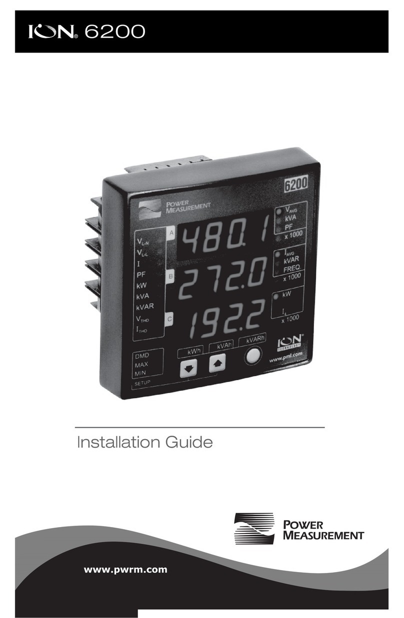
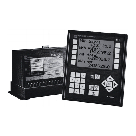
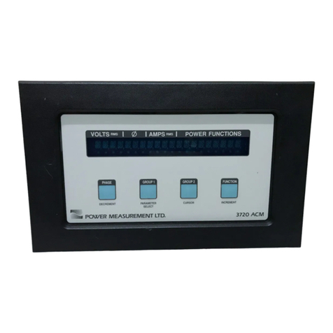
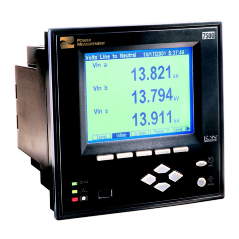
Power Measurement 7330 ION User manual

Users Guide
Version 2.0
CONTENTS

Danger
During normal operation of this device, hazardous voltages are present which can
cause severe injury or death. These voltages are present on the terminal strips of the
device and throughout the connected potential transformer (PT), current transformer
(CT), status input, relay, and control power circuits. Installation and servicing should
be performed only by qualified, properly trained personnel. See the 7330 ION
Installation & Basic Setup Instructions for further details.
Warning
This equipment generates, uses, and can radiate radio frequency energy and if not
installed and used in accordance with the instructions manual, may cause interference
to radio communications. It has been tested and found to comply with the limits for a
Class A computing device pursuant to Part 15 of FCC Rules, which are designed to
provide reasonable protection against such interference when operated in a commer-
cial environment. Operation of this equipment in a residential area may cause
interference in which case the operator will be required to take whatever measures
may be required to correct the interference.
Limitation of Liability
Power Measurement Limited reserves the right to make changes in the
devices or the device specifications identified in this Retrofit Installation Instructions
without notice. Power Measurement Limited advises customers to obtain the latest
version of device specifications before placing orders to verify that the information
being relied upon by the customer is current.
In the absence of written agreement to the contrary Power Measurement Limited
assumes no liability for Power Measurement Limited applications assistance,
customer’s system design, or infringement of patents or copyrights of third parties by
or arising from the use of devices described herein. Nor does Power Measurement
Limited warrant or represent that any license, either expressed or implied, is granted
under any patent right, copyright, or other intellectual property right of Power
Measurement Limited covering or relating to any combination, machine, or
process in which such device might be used.
EXCEPT TO THE EXTENT PROHIBITED BY APPLICABLE LAW, UNDER NO
CIRCUMSTANCES SHALL POWER MEASUREMENT LIMITED BE LIABLE FOR
CONSEQUENTIAL DAMAGES SUSTAINED IN CONNECTION WITH SAID
PRODUCT AND POWER MEASUREMENT LIMITED NEITHER ASSUMES NOR
AUTHORIZES ANY REPRESENTATIVE OR OTHER PERSON TO ASSUME FOR IT ANY
OBLIGATION OR LIABILITY OTHER THAN SUCH AS IS EXPRESSLY SET FORTH
HEREIN.
ION and PEGASYS are registered trademarks of Power Measurement Limited.
7330 ION, Vista, and ION Designer are trademarks of Power Measurement Limited.
Modbus is a registered trademark of Modicon Corporation. Windows, Windows 95,
Windows NT, are registered trademarks of Microsoft Corp.
© 1998 Power Measurement Ltd.
The information contained in this document is believed to be
accurate at the time of publication, however, Power Measurement
Ltd. assumes no responsibility for any errors which may appear
here and reserves the right to make changes without notice.
Toll Free
1-877-METER-IT
(1-877-638-3748)
World-Wide Web www.pml.com
Worldwide Headquarters
POWER MEASUREMENT LTD.
2195 Keating Cross Road,
Saanichton, BC,
Canada V8M 2A5
Tel: 1-250-652-7100
Fax: 1-250-652-0411
Europe & Middle East
POWER MEASUREMENT EUROPE
Zaventem Business Park,
Ikaroslaan 5, B-1930 Zaventem
(Brussels), Belgium
Tel: 32-2-720-19-19
Fax: 32-2-720-95-86
Asia & Pacific
POWER MEASUREMENT AUSTRALIA
7/16 Ledgar Road,
Balcatta, Perth
Western Australia 6021
Tel: 61-9-345-3866
Fax: 61-9-345-3899
Revision Date: September 21, 1998
© 1998 Power Measurement Ltd.
All rights reserved
Printed in Canada
70000-0113
For further information or technical assistance, please
contact your local Power Measurement representative,
or Customer Service at one of the following locations:
ISO 9002-94
Registration
Cert # 002188
Basic communications settings (baud rate, protocol) and metering settings
(volts mode, CT/PT ratios) must be configured before you can use the 7330
ION. If these settings have not been configured, follow the steps in the 7330
ION Installation & Basic Setup Instructions before consulting this User’s Guide.
You may only need to read certain sections of this User’s Guide, depending on
how you will use the 7330 ION.
♦9RHIVWXERHMRKXLI&EWMGWSJXLI-32
Chapter 1 introduces the 7330 ION, and shows how it fits into power monitoring
systems. The display and analysis software tools that compliment the 7330 ION
are discussed, and some of the device’s capabilities are presented.
♦%GGIWWMRK(EXEERH-RXIVTVIXMRK(MWTPE]W
Chapter 2 shows you how to access the data that the factory-configured 7330 ION
provides. Go directly to this chapter if you want to start viewing real-time data
without performing any additional configuration. Chapter 2 describes what data
you can access using PEGASYS Vista software, PowerView software, and the
front panel display.
♦1EOMRK1MRSV'SRJMKYVEXMSR'LERKIW
Chapter 3 describes how to use PEGASYS ION Designer to make minor changes
to the meter’s operation. Configuration functions provided by PowerView and
the front panel are also described.
♦'YWXSQM^MRKXLI-329WMRK%HZERGIH*YRGXMSRW
Chapter 4 provides more details about the 7330 ION’s operating software so that
the advanced user can create custom functions by linking ION modules. Chapter
4 also describes advanced communications and I/O functions available with the
7330 ION. Creating custom front panel displays is also discussed.
♦8IGLRMGEP7TIGMJMGEXMSRW
The Technical Reference in Chapter 5 provides technical specifications, accuracy
data, ordering options, and warranty/registration information.
♦6IZIRYI1IXIVMRK
Details specific to the revenue-class 7330 ION -RMANSI and –RMICAN are
provided in the Appendix.
'LETXIV
'LETXIV
'LETXIV
'LETXIV
'LETXIV
%TTIRHM\%

LLL
'SRXIRXW
4S[IV7XEVX M
-RXVSHYGXMSR
The 7330 ION is Factory-Configured and Ready to Operate ..................................... 1-2
What’s New in 7330 Firmware Version 7330V20x ..........................................................1-2
The 7330 ION in a Power Monitoring System.............................................................. 1-3
Data Display and Analysis Tools ......................................................................................1-3
I/O Options.......................................................................................................................... 1-4
Using this Guide ................................................................................................................1-5
Before You can Use this Guide ..........................................................................................1-6
Getting More Information.................................................................................................. 1-6
(MWTPE]MRK(EXE
Displaying Data with PEGASYS Vista 2.0.................................................................... 2-2
Summary of Data Provided................................................................................................2-2
Common Diagram Elements..............................................................................................2-3
Displaying Data if PEGASYS is not Fully Configured ...................................................2-3
Real-Time Measurements...................................................................................................2-4
Power Quality Data............................................................................................................. 2-5
Energy & Demand Calculations ........................................................................................2-6
Setpoints ...............................................................................................................................2-7
Digital Inputs ....................................................................................................................... 2-8
Displaying Additional Data in Vista.................................................................................2-9
Displaying Data with PowerView................................................................................ 2-10
Summary of Data Provided..............................................................................................2-10
PowerView’s Data Screens Mode....................................................................................2-11
Selecting Different Display Screens ................................................................................ 2-11
The PowerView Data Filter..............................................................................................2-11
Displaying Data with the Front Panel.......................................................................... 2-12
Data Display Screens.........................................................................................................2-12
Display Screen Options ....................................................................................................2-12
Complete List of Factory-Configured Measurements and Functions ........................ 2-15
Energy & Demand Framework........................................................................................ 2-15
Min/Max Framework.......................................................................................................2-16
Historic Data Logging Framework .................................................................................2-19
Setpoint Framework.......................................................................................................... 2-20
Digital Inputs Framework................................................................................................2-20
Real Time Measurements (Core Modules).....................................................................2-21

LY
1EOMRK'SRJMKYVEXMSR'LERKIW r
Configuration Tools ..........................................................................................................3–2
Basics of the ION Architecture........................................................................................3–3
The ION Module................................................................................................................. 3–3
ION Registers...................................................................................................................... 3–4
Making ION Configuration Changes .............................................................................. 3–4
Configuring the 7330 ION with ION Designer............................................................3–5
The Main 7330 ION Configuration Screen ...................................................................... 3–5
Using ION Designer to Change Setup Registers............................................................ 3–5
Basic Configuration............................................................................................................ 3–7
Communications Setup...................................................................................................... 3–8
Communications Protocols ............................................................................................... 3–8
Demand Setup..................................................................................................................... 3–9
Meter Clock Setup .............................................................................................................. 3–9
Setpoint Setup ................................................................................................................... 3–10
Advanced Setup................................................................................................................ 3–10
Third-Party Protocols....................................................................................................... 3–11
Configuring a Communications Protocol...................................................................... 3–11
Factory Information ......................................................................................................... 3–12
Configuring the 7330 ION with PowerView...............................................................3–13
Using the PowerView Interface...................................................................................... 3–13
PowerView’s Setup Screens Mode................................................................................. 3–13
PowerView’s Basic and Advanced ION Setup Modes ................................................ 3–14
Determining Which Modules to Configure .................................................................. 3–15
Configuring the 7330 ION with the Front Panel ........................................................3–16
The Front Panel’s Setup Menus...................................................................................... 3–16
Accessing the Setup Menus............................................................................................. 3–16
Navigating Menus............................................................................................................ 3–17
Editing Registers...............................................................................................................3–17
Password Security ............................................................................................................ 3–18
Clear Functions.................................................................................................................3–19
Quick Setup....................................................................................................................... 3–20
Advanced Meter Setup .................................................................................................... 3–21
Display Setup, Screen Setup, and Nameplate Info....................................................... 3–22
Changing the 7330 ION’s Password .............................................................................. 3–22
Diagnostics ........................................................................................................................ 3–23
9WMRK%HZERGIH*IEXYVIW r
Customizing the 7330 ION’s Operation.........................................................................4–2
ION Details.......................................................................................................................... 4–3
Module Linking Restrictions............................................................................................. 4–3
The Not Available Value ................................................................................................... 4–4
Core Modules and Fixed Module Links.......................................................................... 4–4
ION Register Details .......................................................................................................... 4–4
Timing Considerations in the 7330 ION.......................................................................... 4–6

Y
Time-Sensitive Modules .................................................................................................... 4–6
Sequence of Module Execution......................................................................................... 4–7
ION Event Priority Groups ............................................................................................... 4–8
External ION Events .......................................................................................................... 4–8
Dismantling the Factory Configuration........................................................................... 4–8
Checking the Processor Power Level............................................................................... 4–9
Deleting Factory-Configured Functions.......................................................................... 4–9
Adding and Linking Modules in ION Designer .......................................................... 4–10
Creating New Modules.................................................................................................... 4–11
Deleting Modules ............................................................................................................. 4–12
Linking Modules .............................................................................................................. 4–12
Editing Existing Frameworks ......................................................................................... 4–13
Using Onboard I/O and the Extension Board.............................................................4–14
Using the Onboard Digital Inputs.................................................................................. 4–14
Using the Onboard Digital Outputs............................................................................... 4–15
Using the Relay Extension Boards (REB Option)......................................................... 4–15
Using the Infrared Port.................................................................................................... 4–15
LED Energy Pulsing......................................................................................................... 4–16
Specifying a Port In an ION Module.............................................................................. 4–17
Residual Current Calculation ........................................................................................4–17
Using the Modbus RTU Protocol..................................................................................4–18
The 7330 ION’s Factory Modbus Configuration .......................................................... 4–18
Modbus Slave Module Settings ...................................................................................... 4–19
Modbus Slave Module Parameter Mapping................................................................. 4–20
Importing Data using Modbus RTU.............................................................................. 4–22
Using the DNP 3.0 Protocol............................................................................................4–23
The 7330 ION’s Factory DNP 3.0 Configuration .......................................................... 4–23
DNP Slave Export Module Settings ............................................................................... 4–24
DNP Options Module Settings ....................................................................................... 4–25
Importing Data using DNP 3.0 ....................................................................................... 4–25
Creating Custom Front Panel Displays........................................................................4–26
Customizing Displays...................................................................................................... 4–26
8IGLRMGEP6IJIVIRGI
ION Module Summary ..................................................................................................... 5-2
Setup Register Creation Defaults.......................................................................................5-2
Input and Output Register Descriptions ..........................................................................5-2
Measurements..................................................................................................................... 5-9
Input Ratings .................................................................................................................... 5-11
Onboard Digital Outputs ............................................................................................... 5-11
Optional Relay Modules................................................................................................. 5-12
Additional Specifications............................................................................................... 5-14
Standards Compliance .................................................................................................... 5-14

YL
Ordering Information ..................................................................................................... 5-15
Basic Model ........................................................................................................................ 5-15
Ordering Example............................................................................................................. 5-16
External Output Device Part Number Summary ....................................................... 5-16
Warranty and Registration ............................................................................................. 5-16
Product Return Procedure................................................................................................ 5-17
Registration ........................................................................................................................ 5-18
-326IZIRYI1IXIVW%
7330 ION-RM Models ........................................................................................................ A-1
7330 ION-RM Options ....................................................................................................... A-1
Differences between Standard and RM Models......................................................... A-1
Revenue Meter Energy Register Labels........................................................................... A-1
Additional Revenue Metering Modules..........................................................................A-2
Security Mechanisms ....................................................................................................... A-2
Traditional “Anti-Tamper” Seals .....................................................................................A-3
Password Protected Min/Max Register Resets.............................................................. A-3
Hardware-based Security..................................................................................................A-3
Configuring the 7330 ION-RM....................................................................................... A-4
Safety Precautions ..............................................................................................................A-4
Configuration Procedure...................................................................................................A-5
CT & PT Selection...............................................................................................................A-5
Checklist for Factory-Sealed 7330 ION-RMICAN ...................................................... A-6
Data Recorder #1 (-RMSEAL only) ..................................................................................A-7
-RHI\ -

-RXVSHYGXMSR
The 7330 ION is a highly advanced digital power meter, suited to many power
monitoring and control applications. This Intelligent Electronic Device (IED)
can take the place of numerous transducers, meters and control circuits in your
power monitoring system. The 7330 ION provides true RMS measurements of
voltage, current, power and energy, complimented by extensive I/O
capabilities, comprehensive logging, and advanced power quality functions.
The 7330 ION can be used effectively in numerous supply side and demand
side operations. Some common applications of the 7330 ION are:
♦Replacement of Analog Transducers
♦Substation Automation
♦Utility Sub-Metering
♦Universal Metering
♦Commercial/Industrial Metering
♦Demand Monitoring
♦Genset Applications
These are just a few of the many possibilities. Contact Power Measurement
Customer Service if you would like assistance with your application.
The 7330 ION Basic Model

-3297)67+9-()
8LI-32MW*EGXSV]'SRJMKYVIHERH6IEH]XS3TIVEXI
Although the 7330 ION is fully customizable, it is shipped from the factory with
many functions pre-configured. Once installation and basic setup are
performed, all of the basic measurements and energy calculations are ready to
operate, right out of the box. Many users will find that the factory configuration
will serve their purposes without performing any additional configuration.
;LEXW2I[MR*MVQ[EVI:IVWMSR:\
Firmware version 7330V205 and later offers many new and enhanced features,
including new power quality functions, new communications and I/O options,
and more ION module types for advanced applications. PEGASYS version 2.0
includes several enhancements that make the 7330 ION easier to set up and use.
(EXE(MWTPE]ERH(IZMGI'SRJMKYVEXMSR-QTVSZIQIRXW
The most significant change to the 7330 ION in the V20x release is found when
you display data or perform configuration functions with PEGASYS Vista, ION
Designer and the front panel.
The data measured by the 7330 ION is now easier to access and interpret in
PEGASYS Vista. A new set of user diagrams, included on the PEGASYS 2.0
release CD, group most of the factory-configured functions onto five main
screens for real-time measurements, power quality monitoring, energy and
demand calculations, setpoints and digital input status.
6IWMHYEP'YVVIRX'EPGYPEXMSR
The 7330 ION provides a residual current calculation for 4-Wire Wye systems.
This value is derived from the residual current from an unbalanced load, so it
typically represents the current flow in the neutral or ground conductor.
2I['SQQYRMGEXMSRWERH-33TXMSRW
New or improved communications and I/O features include:
♦Support of DNP 3.0 protocol on all communications ports.
2I[-321SHYPIW
New ION modules are included that provide more options to the advanced
user:
♦DNP Import, Export and Options modules for DNP 3.0 communications.
♦Convert modules for converting different types of data.
♦Feedback modules for creating circular linkages in ION frameworks.

-2863(9'8-32
8LI-32MRE4S[IV1SRMXSVMRK7]WXIQ
Applications that include the 7330 ION, or any other IED, typically require
additional equipment. Display and analysis software tools are almost always
used to manage, interpret and distribute the data measured or logged by an
IED. Usually there are a variety of tools used, and often these tools are
connected using different communications standards and protocols. In many
cases, an IED must also provide control capabilities and device-level data
sharing.
The 7330 ION can adapt to many situations. Advanced communications allow
data to be shared simultaneously across multiple networks, digital outputs
provide control capabilities, and a variety of display and analysis tools can be
used to monitor your power system. This manual discusses the 7330 ION as it
is most commonly used — as a part of a complete power monitoring system.
PowerView
software
Inputs/Outputs
Power System Connections
Display and
Analysis Tools
Real-time measurements,
energy pulses, control signals
Pulser, breaker closures,
digital signals
phase voltage and phase current
from Wye, Delta or single-phase
power systems
distributed
PEGASYS
software
components
corporate network
Communications Options
RS-485
Infrared communications port
ION, Modbus RTU, and DNP3.0
protocols
RMD Unit
(for TRAN models)

-3297)67+9-()
(EXE(MWTPE]ERH%REP]WMW8SSPW
The 7330 ION integrates seamlessly with the display and analysis software
available from Power Measurement. The data acquired by the 7330 ION can be
used in a variety of systems; however, Power Measurement software is
designed to make use of the advanced capabilities the unit provides.
4S[IV1IEWYVIQIRXW4)+%7=77SJX[EVI
You will get the most out of the 7330 ION using Power Measurement’s
PEGASYS software suite. When PEGASYS is used, the 7330 ION becomes part
of a fully networked information system, together with other Power
Measurement IEDs and local and wide-area computer networks. PEGASYS
provides tools for power monitoring, analyzing real-time data, generating
power system reports, and creating custom functionality at the IED level.
PEGASYS is recommended for all power monitoring systems where advanced
analysis and control capabilities are required.
4S[IV1IEWYVIQIRXW4S[IV:MI[7SJX[EVI
The 7330 ION can be installed in power monitoring systems that use Power
Measurement’s PowerView software. PowerView provides real-time display
and analysis features, and complete device configuration capabilities.
PowerView provides a low-cost solution for smaller power system where the
advanced features of PEGASYS are not required.
8LI-32W6IQSXI1SHYPEV(MWTPE]
The Remote Modular Display can be added to an existing 7330 ION-TRAN
model to facilitate local monitoring and standalone applications. The 7330
ION Basic Model provides an integrated front panel display.
Both the front panel and RMD combine real-time display features with
limited device configuration functions. When used in combination with a
PEGASYS or PowerView system, the display provides an interface for field
personnel.
8LMVH4EVX]8SSPW
The 7330 ION can be integrated into various industry-standard networks. Data
that is measured by the unit can be made available to other devices using
Modbus or DNP 3.0 protocols. Data from devices on these networks can also be
imported into the 7330 ION. With these advanced communications functions,
the power of the 7330 ION can be utilized in most existing power monitoring
systems. Any data display and analysis software that works with Modbus or
DNP devices will also work with the 7330 ION.
-33TXMSRW
Four optically isolated digital inputs and four digital outputs are available on
the 7330 ION. Up to four digital input or four digital output modules can be
added. Refer to the section “Using Onboard I/O and the Extension Board” in
Chapter 4 for details.

-2863(9'8-32
The standard 7330 ION has two RS-485 communications ports and one infrared
port. These ports are capable of data rates up to 19,200 bps. The 7330 ION
infrared port on the front panel is compatible with an ANSI C12.13 Type II
magnetic optical communications coupler. It can be used to communicate real-
time measurements via ION, DNP 3.0, or Modbus protocols.
The RS-485 and infrared ports can communicate simultaneously.
6)&3TXMSR
Adding the Relay Extension Board (REB) option can enhance the functionality
of the onboard digital outputs. The REB option includes a four-position Grayhill
module rack and a 100-240VAC to 5VDC power supply. Grayhill modules are
ordered separately.
9WMRKXLMW+YMHI
This User’s Guide is directed at three types of user: the typical user or operator,
the system administrator, and the advanced user. You might not fit into any of
these groups directly, or perhaps you are both an operator and an
administrator. These user classifications are intended to make this guide easier
to navigate.
♦8]TMGEP9WIVSV3TIVEXSV
Most users will simply want to display the data provided by the factory-
configured 7330 ION. These users want fast access data through the front
panel, PEGASYS software, PowerView software or a third-party protocol
such as Modbus or DNP.
Chapter 2 addresses the needs of the typical user who wants to get data out
of the 7330 ION. This chapter assumes that the reader is not concerned with
how the device functions; instead the focus is on accessing and interpreting
the data provided.
♦7]WXIQ%HQMRMWXVEXSVSV1EREKIV
Some users will need to make minor adjustments so that their devices “fit”
their power systems: communications settings, demand sub-intervals and
other parameters may need to be set before the 7330 ION’s setup is
complete. These users will use the front panel, PowerView software or
PEGASYS software to change settings in the device’s operating software.
(PEGASYS is highly recommended for device configuration.)
Chapter 3 is directed at the user who wants to get more out of the 7330 ION
by making adjustments to its factory-configured functionality. This chapter
focuses on the different configuration changes that can be made with
minimal effort, and what effects each type of setting will have. Very few
details about the device’s internal operation are provided.

-3297)67+9-()
♦%HZERGIH9WIVSV7]WXIQW-RXIKVEXSV
Advanced users may want to make use of the flexibility and power
provided by the device’s ION operating software. These users will need to
become familiar with the ION Architecture and the PEGASYS tools used to
customize the meter’s operation.
Chapter 4 is useful for the advanced user who wants to become familiar
with the device’s internal operation and its more sophisticated capabilities.
This chapter is designed to facilitate different applications by providing
background information and detailed functional descriptions — specific
applications are only discussed to illustrate a particular function.
Configuration instructions for particular applications can be found in Power
Measurement Application Notes, available from Power Measurement
Customer Service.
&IJSVI=SYGER9WIXLMW+YMHI
By the time you are ready to use this Guide, your 7330 ION should be installed,
basic setup should have been performed, and communications/basic operation
should have been verified. If the unit is not yet installed and operational, refer
to the 7330 ION Installation & Basic Setup Instructions shipped with the meter.
+IXXMRK1SVI-RJSVQEXMSR
Additional information is available from Power Measurement. Check our web
site at www.pml.com, contact your local Power Measurement representative, or
contact Power Measurement directly. (Contact information is provided on the
first page of this document.) Documents related to the installation, operation
and application of the 7330 ION:
7330 ION Installation & Basic Setup Instructions
This brief guide is shipped with each 7330 ION. It details the mounting, wiring
and basic setup of the device.
ION Reference
The reference manual contains detailed descriptions of all of the modules in
each ION device.
PEGASYS 2.0 Administrator’s Guide
This guide explains the installation and configuration of the PEGASYS software
suite. Advanced PEGASYS tools are described.
PEGASYS ION Designer Online Help
This describes how to use PEGASYS ION Designer.
PEGASYS Vista User’s Guide
This guide describes how to use PEGASYS Vista.
PowerView On-Line Help
This describes how to use PowerView.

(MWTPE]MRK(EXE
The 7330 ION is shipped from the factory with a comprehensive configuration.
Most users will find that the factory configuration suits their needs entirely.
This chapter describes how to view the data that is measured by the factory-
configured 7330 ION using PEGASYS Vista software, PowerView software and
the front panel interface.
The 7330 ION’s factory configuration also includes some data that does not
appear by default in PEGASYS Vista, PowerView or on the front panel. Further,
the factory configuration makes several power, energy and demand parameters
available through the Modbus RTU protocol. A list of available data that does
not appear in PEGASYS Vista, PowerView or on the front panel is presented
near the end of this chapter, and how to view it is briefly discussed.
-RXLMW'LETXIV
♦Displaying Data with PEGASYS Vista 2.0......................................................... 2-2
Summary of Data Provided........................................................................ 2-2
Common Diagram Elements...................................................................... 2-3
Displaying Data if PEGASYS is not Fully Configured ........................... 2-3
Real-Time Measurements ........................................................................... 2-4
Power Quality Data ..................................................................................... 2-5
Energy & Demand Calculations ................................................................ 2-6
Setpoints........................................................................................................ 2-7
Digital Inputs................................................................................................ 2-8
Displaying Additional Data in Vista......................................................... 2-9
♦Displaying Data with PowerView.................................................................... 2-10
Summary of Data Provided...................................................................... 2-10
PowerView’s Data Screens Mode............................................................ 2-11
Selecting Different Display Screens......................................................... 2-11
The PowerView Data Filter ...................................................................... 2-11
♦Displaying Data with the Front Panel.............................................................. 2-12
Data Display Screens................................................................................. 2-12
Display Screen Options............................................................................. 2-12
♦Complete List of Factory-Configured Measurements and Functions ......... 2-15

-3297)67+9-()
(MWTPE]MRK(EXE[MXL4)+%7=7:MWXE
PEGASYS Vista version 2.0 is the premiere display and analysis tool for the 7330
ION and other Power Measurement IEDs. A standard set of Vista User
Diagrams displays real-time data for various power system parameters.
Interactive objects are provided on the diagrams that allow operators with
appropriate PEGASYS authority to reset cumulative parameters.
7YQQEV]SJ(EXE4VSZMHIH
The standard set of three Vista diagrams included with PEGASYS 2.0 display a
variety of the data measured by the factory-configured 7330 ION. Some of the
diagrams include grouping windows that display additional data. The
following list summarizes the data available from the standard diagrams; more
detail is provided in the next few pages.
6IEP8MQI1IEWYVIQIRXW
♦Line-to-neutral voltages, line-to-line voltages, average L-N and L-L voltages
and voltage unbalance level
♦Phase currents and average current
♦Phase kW, total kW, kVAR and kVA
♦Frequency and signed power factor
♦Min/max display of each of the above parameters
♦All logged meter events
♦Trend logs of voltage, current, power, frequency and power factor
4S[IV5YEPMX](EXE
♦Phase voltage and current total harmonic distortion (THD)
♦Min/max display of phase voltage and current THD
♦Logged average and maximum THD and K factor
)RIVK](IQERH(EXE
♦Real-time and peak kW, kVAR and kVA sliding window demand
♦Real-time net kWh, net kVARh and kVAh energy values
♦Trend log of all of the above parameters, plus power factor lead and lag,
imported, exported and net energy
7IXTSMRXW
♦Monitoring of kW demand, phase current and voltage unbalance
conditions, with annunciation when user-specified upper limit is exceeded
♦Real-time display of kW demand, phase current and voltage unbalance
238)
0DQ\ RI WKH GLDJUDPV DOVR
SURYLGH LQWHUDFWLYH FRQWURO DQG
SDUDPHWHUUHVHWIXQFWLRQV

(-740%=-2+(%8%
(MKMXEP-RTYXW
♦Monitoring of the 7330 ION’s four on-board status inputs
♦Status change counter for each input
'SQQSR(MEKVEQ)PIQIRXW
Each diagram shows the name of the device, the time on the device’s clock, and
the type of device. The three main diagrams also provide buttons that let you
jump to other diagrams. Double-click any of the buttons near the top right-
hand corner to jump to the associated diagram (this is illustrated in the Real-
Time Measurements section below).
(MWTPE]MRK(EXEMJ4)+%7=7MWRSX*YPP]'SRJMKYVIH
The PEGASYS 2.0 Administrator’s Guide, shipped with PEGASYS 2.0, provides a
set of guidelines that should be followed during commissioning. If PEGASYS
2.0 has been installed and configured using the recommended guidelines, the
standard Vista user diagrams display real-time data from your 7330 ION
automatically.
If commissioning has not been completed (or if commissioning was performed
without following the guidelines) some effort may be required to view 7330
ION data in Vista 2.0. If you are not able to run the PEGASYS Communications
Server, Log Server or Vista, you will need to complete PEGASYS commissioning
before you can display data from your 7330 ION. Contact your PEGASYS
Administrator or refer to the PEGASYS 2.0 Administrator’s Guide before
continuing with this User’s Guide.
If you can run PEGASYS Vista and log on, you can probably access data from
your 7330 ION. Try performing the following steps in Vista:
1. Log on to Vista with Supervisor authority (Level 5).
2. Select Generate Network Diagram from the File menu.
3. In the Network Diagram, double-click the Workstation icon corresponding
to the computer that communicates with the 7330 ION. A new diagram
with all available IEDs appears.
4. Double-click the icon for the 7330 ION. The Real-Time diagram appears,
and live data should appear within moments.
You should now be able to move around through the various diagrams and
view real-time and logged data.
238)
5HIHU WR WKH
! c#
H ¦c?H
LI \RX QHHG KHOS
XVLQJ9LVWD
238)
,I \RX FDQ·W GLVSOD\ GDWD LQ
3(*$6<6 9LVWD DQG \RX GRQ·W
KDYH /HYHO DXWKRULW\ FRQWDFW
\RXU3(*$6<6DGPLQLVWUDWRU

-3297)67+9-()
6IEP8MQI1IEWYVIQIRXW
The Real-Time diagram includes a simple power system illustration that shows
various real-time parameters. The diagram also includes links to a min/max
parameter display.
0SRKXIVQ1MR1E\
♦Double-click the Long-term Min/Max object to see a Vista grouping
window showing min/max values for line-to-line and line-to-neutral
voltages, voltage unbalance, phase currents, power values (kVA, kVAR and
kW), frequency, and power factor.
♦Level 3 PEGASYS authority is required to reset the min/max values.
♦To return to the real-time diagram, use the Up One Level button on the
Vista toolbar; or use the File, Up One Level menu item.
♦Min/max values are valid from the time the meter was powered up, or
valid from the time the last reset was performed.
,MWXSVMG(EXE0SKKMRK)REFPI
♦The Log Server must be running to view historical data.
♦Historic data logging is enabled by default.
♦Level 3 PEGASYS authority is required to use the enable control object.
♦The control object indicates the logging enable status: the switch is in the up
position (1) when logging is enabled, and down (0) when logging is
disabled.
7KLV DUHD UHSUHVHQWV \RXU
SRZHUV\VWHP$%DQG&DUH
WKHSKDVHVDQG1LV QHXWUDO
9
ROWDJH XQEDODQFH LV VKRZQ
EHORZWKHOLQHGLDJUDP
/LQHWROLQHYROWDJHV
3KDVHFXUUHQW
3KDVH
S
RZHU
/LQHWRQHXWUDOYROWDJHV
'RXEOHFOLFN WR VHH WKH
PLQPD[ VFUHHQ 0LQPD[
UHVHWLVDYDLODEOHKHUH
'RXEOHFOLFN WKLV EXWWRQ
WR UHWXUQ WR WKH 1HWZRUN
'LDJUDP
'RXEOHFOLFNDQ\RIWKHVH
EXWWRQV WR MXPS WR WKH
FRUUHVSRQGLQJGLDJUDPV
'RXEOHFOLFN WR
VHH WKH PHWHU·V
HYHQW
OR
J
'RXEOHFOLFN WKLV REM
HFW WR HQDEOH RU
GLVDEOHGDWDORJJLQJ
'RXEOHFOLFN
DQ\ RI WKHVH
EXWWRQVWRVHH
GDWDORJV

(-740%=-2+(%8%
4S[IV5YEPMX](EXE
The Power Quality diagram shows harmonics details. The harmonics
measurement display shows total harmonic distortion for each phase of voltage
and current. Links to harmonics min/max and harmonics trending displays are
provided, and a control object is included for enabling/disabling harmonics
logging.
,EVQSRMGW1IEWYVIQIRXW
♦Total Harmonics Distortion (THD) is displayed as a percentage of phase
measurements.
0SRKXIVQ1MR1E\
♦Double-click the Long-term Min/Max object to see a Vista grouping
window showing min/max values for phase voltage and current THD.
♦Level 3 PEGASYS authority is required to reset the min/max values.
,EVQSRMGW8VIRHMRK
♦The Log Server must be running to view the logged harmonics data.
♦Harmonics data logging is enabled by default.
♦Level 3 PEGASYS authority is required to use the enable control object.
7KLV DUHD VKRZV
SHUSKDVHYROWDJH
DQG
FXUUHQW
7+'
'RXEOHFOLFN WKLV
REMHFW WR YLHZ WKH
KDUPRQLFVGDWDORJ
'RXEOHFOLFNWKLVREMHFW WR
YLHZ KDUPRQLFV PLQPD[
GDWD 0LQPD[ UHVHW LV
DYDLODEOHKHUH

-3297)67+9-()
)RIVK](IQERH'EPGYPEXMSRW
The Energy & Demand diagram shows the real-time sliding window demand
for kW, kVA and kVAR, and the real-time energy values kWh net, kVARh net
and kVAh. Peak demand is displayed for kW, kVAR and kVA, and a link to a
demand profile trend is provided. Control objects for enabling/disabling
demand logging and resetting energy and demand values are also included.
(IQERH)RIVK]ERH4IEO(IQERH6IWIX
♦Level 3 PEGASYS authority is required to reset these values.
(IQERH4VSJMPI8VIRHMRK
♦The Log Server must be running to view the energy and demand log.
♦Energy and demand logging is enabled by default.
♦Level 3 PEGASYS authority is required to use the enable control object.
♦The control object indicates the logging enable status: the switch is in the up
position (1) when logging is enabled, and down (0) when logging is
disabled.
1HWHQHUJ\YDOXHV
6OLGLQJZLQGRZGHPDQG
3HDN VOLGLQJ ZLQGRZ
GHPDQG
3DUDPHWHUUHVHWEXWWRQV
'RXEOHFOLFNWKLVREMHFW
WRVHHWKHHQHUJ\DQG
GHPDQGORJ
'RXEOHFOLFNWKLVREMHFWWR
HQDEOHRUGLVDEOHHQHUJ\
DQG
GHPDQG
OR
JJ
LQ
J

(-740%=-2+(%8%
7IXTSMRXW
The Setpoints diagram uses setpoints to monitor kW demand, over current and
under average voltage and power factor levels. Vista annunciates warnings if
any of the values exceed specified limits. Users with Level 3 PEGASYS
authority can define the setpoint limits.
3ZIVO;7PMHMRK;MRHS[(IQERH1SRMXSVMRK
♦Over kW demand monitoring is disabled by default.
♦Level 3 PEGASYS authority is required to enable this monitoring.
♦The status will read “Not Available” when monitoring is disabled.
3ZIV%ZIVEKI'YVVIRX1SRMXSVMRK
♦Over current monitoring is disabled by default.
♦Level 3 PEGASYS authority is required to enable this monitoring.
♦Each status will read “Not Available” when monitoring is disabled.
9RHIV%ZIVEKI:SPXEKI0MRIXS0MRI1SRMXSVMRK
♦Over voltage monitoring is disabled by default.
♦Level 3 PEGASYS authority is required to enable this monitoring.
♦The status will read “Not Available” when monitoring is disabled.
9RHIV4S[IV*EGXSV1SRMXSVMRK
♦Under power factor monitoring is disabled by default.
♦Level 3 PEGASYS authority is required to enable this monitoring.
♦The status will read “Not Available” when monitoring is disabled.
0RQLWRUHDFK
VHWSRLQW·V
VWDWXVHVKHUH
'RXEOHFOLFN WKHVH
REMHFWVWRHQDEOHRU
GLVDEOHPRQLWRULQJ
Table of contents
Other Power Measurement Measuring Instrument manuals

Power Measurement
Power Measurement 3720 ACM User manual

Power Measurement
Power Measurement ION 8000 Series User manual

Power Measurement
Power Measurement 3710 ACM User manual

Power Measurement
Power Measurement ION 8300 User manual

Power Measurement
Power Measurement ION 7700 User manual

Power Measurement
Power Measurement 3300 ACM User manual

Power Measurement
Power Measurement ION 8800 User manual

Power Measurement
Power Measurement ION 6200 User manual

Power Measurement
Power Measurement 3300 ACM User manual

Power Measurement
Power Measurement ION 8300 User manual