SmartOne 70-600000-001 User manual

TM
Effective: October 2016
Remote Releasing Module
DESCRIPTION
The Remote Releasing Module (RRM) is a UL Listed, FM Approved
SmartOne® Field Device. The RRM provides the ability to remotely activate
extinguishing-system control devices. Connection is via the SmartOne com-
patible control panel’s Signaling Line Circuit (SLC). The module is eld-pro-
grammable using the control panel keypad or Hand-Held Programmer.
The RRM provides internal supervision of communication with the control
unit, connections to external power supply, and memory status.
Solenoid release circuits are power-limited and supervised for short circuit
by using an In-line Releasing-Circuit Device (P/N 06-220023-001). In the
event of a ground fault, open, short or a relay contact failure, the device
will transmit a trouble status to the control unit.
A status LED is mounted on the RRM and indicates the module’s status:
Normal is indicated by a ash every 9 seconds; Output Activity is indicated
by the LED on continuously (no ashing); Trouble is indicated by the LED
being OFF.
The RRM is intended for indoor dry location use, and is available in two
models, one for mounting in a standard electrical box and a second model
for mounting in suitable UL-864 Listed cabinets.
P/N 70-600000-001: Standard Mounting
•North American 4-11/16 in. electrical box with a double gang plaster
ring (Rayco Model 841 or equivalent), 1/2 in. raised
•4 in. square, 2-1/8 in. deep electrical box
P/N 70-600000-002: In-Cabinet Mounting
•Any suitable UL-864 Listed enclosure with no other electronics.
The module terminal block will accept #12, #14, #16 and #18 AWG wire
(4.0 mm2, 2.5 mm2, 1.5 mm2 and 1.0 mm2 respectively). Size #18 being a
minimum requirement. The use of solid wire is recommended.
TM
KIDDE-FENWAL INC.
400 MAIN STREET, ASHLAND, MA 01721
TEL: (508) 881-2000 FAX: (508) 881-8920
This literature is provided for informational purposes only.
KIDDE-FENWAL,INC. assumes no responsibility for the
product’s suitability for a particular application. The product
must be properly applied to work correctly.
If you need more information on this product, or if you have
a particular problem or question, contact KIDDE-FENWAL
INC., Ashland, MA 01721. Telephone: (508) 881-2000
06-236636-001 Rev. AD ©2016 Kidde-Fenwal, Inc.
INSTALLATION INSTRUCTIONS
This device complies with Part 15 of the FCC rules. Operation is subject to the following two
conditions: (1) This device may not cause any harmful interference, and (2) This device must
accept any interference received, including interference that may cause undesired operation.
Control Unit
Part Number
Installation,
Operation and
Maintenance Manual
Part Number
Configuration
Software
User's Guide
Part Number
FenwalNET 6000:
74-600000-00106-236529-00106-236529-002
74-600000-51006-236529-00106-236529-002
ARIES:
76-600000-00406-236530-00106-236530-002
FenwalNET 8000-ML:
74-800100-00106-237041-00106-237042-001
74-800101-00206-237041-00106-237042-001
74-800200-00106-237041-00106-237042-001
74-800201-00206-237041-00106-237042-001
ARIES NETLink:
76-800100-00106-237058-00106-237059-001
76-800101-00206-237058-00106-237059-001
76-800200-00106-237058-00106-237059-001
76-800201-00206-237058-00106-237059-001
74-800102-00106-237041-00106-237042-001
74-800202-00106-237041-00106-237042-001
76-800102-00106-237058-00106-237059-001
76-800202-00106-237058-00106-237059-001
2 7
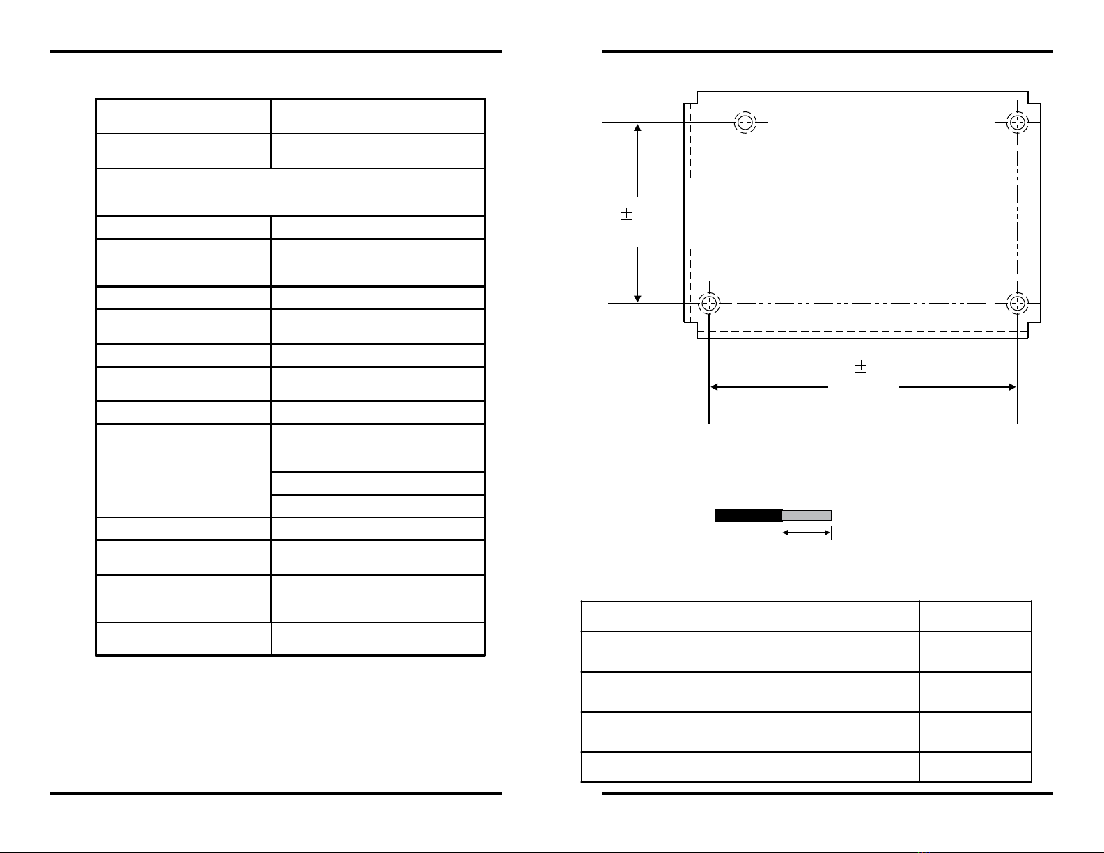
3.00 in.
0.01 in.
1.80 in.
0.01 in.
Figure 5. RRM Mounting Template
ORDERING INFORMATION
Description Part Number
Remote Releasing Module
(With Standard Bracket and Front Cover Plate) 70-600000-001
Remote Releasing Module
(With In-Cabinet Bracket and Mounting Hardware) 70-600000-002
Inline Releasing Device (One Required For Each Solenoid
Release Circuit to be Supervised and Power Limited) 06-220023-001
End of Line Resistor, 4.7 K, 0.5 W 06-129025-006
SPECIFICATIONS
WIRE STRIPPING
Strip 1/4 in. from the ends of all wires that connect to the terminal block of the
module.
1/4 in.(6.4mm)
Figure 1. Wire Stripping
Single-Loop Panel Activation * Up to 4 groups of 16 RRMs activated
simultaneously
Multi-Loop Panel Activation * Up to 7 groups of 20 RRMs activated
simultaneously
*For further information on activation of RRMs, refer to the applicable
Installation, Operation and Maintenance manual and Configuration Software
User's Guide for your control unit.
Operating Voltage 24 VDC Nominal
Device Current (Remote Supply)
6.1 mA Standby
45 mAAlarm (Excluding Releasing
Devices)
Device Current (SLC) 410 µA Standby and Alarm
Operating Temperature Range 32ºF to 120ºF
(0ºC to 49ºC)
Operating Humidity Range 0% to 93% RH
Construction High Impact Polymer Faceplate with a 16
gauge Aluminum Bracket
Shipping Weight 10.5 oz (298 g)
Compatible Electrical Boxes
North American 4-11/16 in. electrical box
with a double gang plaster ring (Rayco
Model 841 or equivalent)
4 in. square 2-1/8 in. deep box
Any suitable UL-864 Listed Enclosure
Releasing Circuit Output Current 2.4A Max. @ 24.0 VDC
Trouble Circuit Input 4.7K End of Line Resistor
"Open" contact = normal condition
SLC Wiring Configuration
•Class A,
•Class B,
•Class A, Style-7
Wiring Unshielded
(See Note 12 for use of shielded wire)
Note: To ensure that all SLC-based output devices are activated within the
required time period, refer to the associated control unit’s Installation,
Operation and Maintenance manual.
3
GENERAL NOTES
1. Terminal connection supports wiring from #18 AWG (1.0 mm2) to #12
AWG (4.0 mm2). Wire sizes determine electrical box depth.
2. Refer to applicable Control Panel Manual for addressable loop wiring
specication.
3. SLC Line wiring is power-limited and supervised.
4. Do not attach power-limited and non-power-limited wiring to the same
terminal block.
5. Route non-power-limited wires at least 1/4 in. away from all power-
limited wiring.
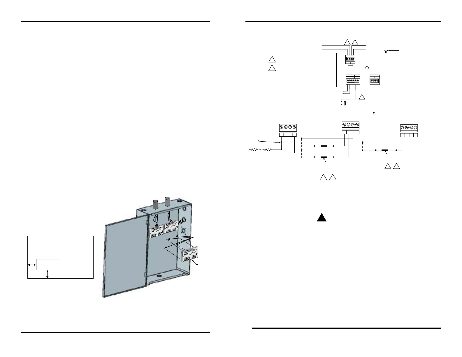
WIRING DIAGRAM
Figure 2. RRM Wiring
6
APPROVED
FM
APPROVED
FM
APPROVED
FM
STANDOFFS
INSULATOR
2. Using the template in Figure 5, mark the mounting holes in the
cabinet that the RRM is going to be installed.
3. Drill the mounting holes in the enclosure.
4. Install provided standoffs in the cabinet mounting holes.
5. Mount the cabinet.
6. Run the necessary wiring and conduit to the cabinet.
Note: See Appendix E of the corresponding Control Unit’s Installa-
tion, Operation and Maintenance Manual for routing guidelines for
power-limited and non-power-limited wiring. Refer to the reference
table on the last page for the part number of the applicable manual.
7. Remove the insulator from the RRM.
8. On the RRM, loosen the mounting screws until each screw is ush
with the back of the module.
9. Place the RRM over the standoffs in the enclosure. Secure the
mounting screws to the standoffs.
10. Make all wiring connections as shown in the wiring diagram.
Ensure that all wiring is free of opens, shorts and ground faults.
Verify that all wires are insulated up to and touching the terminal
block, and that each terminal screw is tight.
11. Replace the insulator on the RRM.
Figure 4. Minimum RRM Clearance and
Mounting the RRM in a UL Listed Enclosure
WARNING
!
Ensure that all releasing devices are physically disconnected from
the releasing circuits before performing any testing or maintenance.
RRM
½ in. (13 mm)
½ in.
(13 mm)
UL LISTED ENCLOSURE
S
S
S
S
SP
P
P
P
REMOTE RELEASE MODULE (RRM)
TB2
TB3
TB1
4.7k EOL
Control Unit
SLC (TB1)
24 VDC Release
+++
-+-
PSU
STATUS
213456
--
TB1
TB1
TB1
Or
DUAL-SOLENOID CIRCUIT SINGLE-SOLENOID CIRCUIT
To next loop device
Blk Red
Blk Red
Blk Red
Current Limiting Resistor
Other Assemblies
See the applicable Control Unit’s
Installation, Operation and
Maintenance Manual for a list of other
compatible releasing devices and
device-specific wiring instructions.
In-Line Releasing Device,
P/N 06-220023-001 (Must be close
nippled to solenoid enclosures)
In-Line Releasing Device, P/N 06-220023-001
(Must be close nippled to solenoid enclosures)
(Non-Power-Limited when an In-Line Releasing
Device not used) See General Note 4.
(W
ircuit is non-power-limited and not supervised
for shorts.)
hen an In-Line Releasing Device is not used, the
c
Supervised for open circuits and ground
faults.
OTHER COMPATIBLE
RELEASING DEVICES
AABB
12 34
SLC
2134
To PSU dry contact trouble relay
(Trouble = contacts closed)
Legend:
Supervised
Power Limited
For a list of all compatible
releasing devices, refer to
Appendix C of the corresponding
Control Unit’s Installation, Operation
and Maintenance Manual.
Release Circuit:
Voltage:
Current:
24 VDC (nom.)
2.4 A(max.)
Or
213421342134
Max. Current under Fault Conditions: 5A
To Earth Ground
(screw on mounting
bracket)
For a list of all compatible
power supplies, refer to
Chapter 1 of the corresponding
Control Unit’s Installation, Operation
and Maintenance Manual.

4
INSTALLATION FOR A 4-11/16 IN. SQUARE OR 4 IN. SQUARE
ELECTRICAL BOX (SEE FIGURE 3)
Note: The depth of the box is to be determined per Article 370 of the National
Electrical Code. RRM volume is 8.94 cubic-inches.
1. It is recommended that the module address be programmed prior to instal-
lation. Refer to the control unit manual for device address programming.
Using a handheld programmer to set the module address requires a 24 VDC
power supply (see Figure 2). A handheld programmer can only program the
module address. All other congurations can be set using with the control
panel or conguration software.
2. Make all wiring connections as shown in the wiring diagram (see Figure 2).
Ensure that all wiring is free of opens, shorts and ground faults. Verify that
all wires are insulated up to and touching the terminal block, and that each
terminal screw is tight. Connect the Earth-Ground to the green screw on the
mounting bracket.
3. Mount the module to the 4 in. square or 4-11/16 in. electrical box (use adapter
ring for the 4-11/16 in. electrical box) .
4. Using the 2 provided screws, mount the wall plate to the electrical box as
shown in Figure 3.
Note: See Appendix E of the corresponding Control Unit’s Installation, Operation
and Maintenance Manual for routing guidelines for power- limited and
non-power-limited wiring. Refer to the reference table on the last page
for the part number of the applicable manual.
6. The RRM is shipped from the factory as an assembled component and
is not eld-serviceable.
7. For ease of wiring, especially with solid wire, an extension ring or deeper
box can be used.
8. For Power-Limited Circuits, use Type FPL, FPLR, or FPLP cable per
Article 760 of the National Electrical Code (NEC). The note located on
product label “ALL OTHERS-POWER LIMITED” must be removed if
connected to a non-power limited supply source.
9. For a list of power supplies, refer to Chapter 1 of the applicable Control
Unit’s Installation, Operation and Maintenance Manual. Refer to the
reference table on the last page for the part number of the applicable
manual.
10. For a list of compatible solenoids, refer to Appendix C of the applicable
Control Unit’s Installation, Operation and Maintenance Manual. Refer to
the reference table on the last page for the part number of the applicable
manual.
11. To congure the RRM, refer to the applicable Control Unit’s Conguration
Software User’s Guide. Refer to the reference table on the last page for
the part number of the applicable user’s guide.
Note: Releasing devices are Control Unit- and Conguration Software-depen-
dent.
12. The use of shielded wire is not allowed for the Release Circuit, PSU
Trouble Circuit and 24VDC Power Circuit, except for very short
runs. The maximum amount of shielded wire which can be spliced into
or used on the referenced circuits is a combined total of 50 feet. When
multiple Remote Release Modules, Addressable Signal Modules, and
Addressable Input Modules attached to the same SLC loop are using
shielded wire on their initiating circuits, remote LED circuits, 24V power
circuits, auxiliary circuits, notication appliance circuits or release circuits,
the total combined shielded wire on all of these circuits (not including the
SLC itself) must not exceed 200 feet. Refer to the control unit Installation,
Operation and Maintenance Manual for SLC loop wiring requirements.
SUPERVISION
Each Circuit is supervised for short circuit (only when using inline device
06-220023-001 for solenoids), open circuit, and ground faults in order to be listed
as power limited. Initiators are an exception; they are not supervised for short
circuits, and are not listed as Non-Power Limited.
5
APPROVED
FM
Figure 3. Mounting the RRM in an Electrical Box
INSTALLATION FOR AN IN-CABINET RRM ENCLOSURE
(SEE FIGURE 4)
The RRM module is intended for mounting inside a suitable UL-864 Listed enclo-
sure with no other electronics. Use the mounting hardware (standoffs and screws)
provided with the module. Provide a minimum 1/2 in. of clearance between the
RRM(s) and enclosure (See Figure 4).
It is recommended that the module address be programmed prior to installation.
Refer to the control panel manual for device address programming. Using a hand-
held programmer to set the module address requires a 24 VDC power supply (see
Figure 2). A handheld programmer can only program the module address. All
other congurations can be set using the control panel or conguration software.
This manual suits for next models
1
Popular Control Unit manuals by other brands

Emerson
Emerson White Rodgers 36C53 Series installation instructions

Burkert
Burkert 0258 operating instructions

Parker
Parker DINCon II Installation, operating, & maintenance instructions

Infineon
Infineon TLE9262-3BQX manual

Telit Wireless Solutions
Telit Wireless Solutions UE910 series Hardware user's guide

Acromag
Acromag BusWorks 900EN Series user manual

Allen-Bradley
Allen-Bradley Rockwell Automation 1734-4IOL user manual

Bosch
Bosch MP 100 Installation instruction

Burkert
Burkert FieldConnect ME64 operating instructions

Just Motion Control
Just Motion Control 2DM860 manual

Vitec Multimedia
Vitec Multimedia Litepanels ASTRA 1X1 manual

Nibco
Nibco Webstone Series manual


