SMAY iSWAY-FC User manual

Operation and Maintenance Manual (DTR) iSWAY®Set of products
Version 1.8 of 2.2021 2
Version 1.8
SMAY reserves the right to make changes to the document.
Table of contents
1. Introduction....................................................................................................................... 6
2. Regulations ....................................................................................................................... 7
2.1. Placing on the market...................................................................................................7
3. Intended use and principle of operation .................................................................... 10
3.1. Intended use and scope of application of iSWAY-FC®, iSWAY-WFC® and
iSWAY-RFC® units.................................................................................................................10
3.2. Operation principles of iSWAY-FC®, iSWAY-WFC® and iSWAY-RFC® units...10
4. Construction of the equipment .................................................................................... 14
4.1. iSWAY-FC®...................................................................................................................14
4.2. iSWAY-WFC® ...............................................................................................................16
4.3. iSWAY-RFC®.................................................................................................................16
5. Performance versions................................................................................................... 17
5.1. iSWAY-FC®....................................................................................................................18
5.2. iSWAY-WFC®................................................................................................................21
5.3. iSWAY-RFC®.................................................................................................................21
6. Accessories for iSWAY .................................................................................................. 25
6.1. iSWAY-FC®...................................................................................................................25
6.2. iSWAY-WFC® ...............................................................................................................25
6.3. iSWAY-RFC®................................................................................................................26
7. Dampers of double air intake system (primary and back-up, components of the
two air intake system). ......................................................................................................... 26
7.1. Basic information ........................................................................................................26
7.2. Technical data of the two damper system...............................................................28
8. Identification of the unit................................................................................................ 29
8.1. Rating plate...................................................................................................................29
8.2. Product labelling rules...............................................................................................30
8.2.1. iSWAY-FC®labelling ...................................................................................................30
8.2.2. iSWAY-WFC® labelling ..............................................................................................31

Operation and Maintenance Manual (DTR) iSWAY®Set of products
Version 1.8 of 2.2021 3
8.2.3. iSWAY-RFC®labelling.................................................................................................32
9. Technical parameters iSWAY-FC®, iSWAY-WFC®, iSWAY-RFC® ....................... 34
9.1. iSWAY-FC®...................................................................................................................34
9.1.1. iSWAY-FC® dimensions .............................................................................................34
9.1.2. Technical parameters of iSWAY-FC® devices........................................................35
9.2. iSWAY-WFC® ...............................................................................................................36
9.2.1. iSWAY-WFC®dimensions..........................................................................................36
9.2.2. Technical parameters of iSWAY-WFC® devices....................................................36
9.3. iSWAY-RFC®................................................................................................................37
9.3.1. iSWAY-RFC® Dimensions ..........................................................................................37
9.3.2. Technical parameters of iSWAY-RFC® devices.....................................................38
10. Transport and storage .................................................................................................. 38
10.1. iSWAY-FC®...............................................................................................................39
10.2. iSWAY-WFC® ...........................................................................................................40
10.3. iSWAY-RFC® ............................................................................................................41
11. Installation ...................................................................................................................... 41
11.1. iSWAY-FC®...............................................................................................................41
11.1.1. Installation of the device.........................................................................................41
11.1.2. Foundation and supporting structures.................................................................43
11.1.3. Place of installation.................................................................................................46
11.1.4. Connection of ventilation ducts .............................................................................46
11.2. iSWAY-WFC® ...........................................................................................................47
11.3. iSWAY-RFC® ............................................................................................................50
11.3.1. iSWAY-RFC® vertical version................................................................................50
11.3.2. iSWAY-RFC® in the horizontal version................................................................51
11.4. Automatic Control Cabinet SzA-FCK ....................................................................53
11.5. Pneumatic connections...........................................................................................53
12. FireBUS®bus loop........................................................................................................ 55
13. Electrical connections and parameters..................................................................... 56
13.1. Power connection, SzA-FCK, SAP.........................................................................56
13.1.1. Main power connection ...........................................................................................57
13.1.2. SzA-FCK connection ................................................................................................58
13.1.3. Connection of SAP signal........................................................................................59
13.2. Electrical parameters .............................................................................................60
13.3. Wiring block diagrams ............................................................................................62

Operation and Maintenance Manual (DTR) iSWAY®Set of products
Version 1.8 of 2.2021 4
13.4. Connection diagrams for SAFETY WAY®/iSWAY® devices (FC, WFC, RFC)..71
13.4.1. TSS, TS, MSPU connection - FireBUS global loop..............................................71
13.4.2. Connection of double intake system, fixed lack of tightness opening damper,
TSS-X-24VDC, 24VDC peripheral device.................................................................................77
13.4.3. Connection of P-MACF pressure transmitters ...................................................78
13.4.4. Connection of the MAC-D-Min regulator and the PZ Connection Box.............83
13.4.5. Connection of MAC-Link card, T-MACF temperature sensors, iSWAY®
booster/reserve..........................................................................................................................87
14. Automation components of the iSWAY-FC®iSWAY-WFC®, iSWAY-RFC® device -
support for the facility manager/administrator............................................................... 91
14.1. Shut-off damper actuator.......................................................................................92
14.2. Damper actuator of double intake module and distribution damper for
Primary and back-up .............................................................................................................93
14.3. Smoke detector in a duct casing ...........................................................................93
14.4. Fans............................................................................................................................97
14.4.1. AFC, ARC and AJF ....................................................................................................97
14.4.2. HCBT ..........................................................................................................................98
14.4.3. iSFS SMAY .................................................................................................................99
14.5. SzA-FCP - automation cabinet...............................................................................99
14.6. SzA-FCK - automation cabinet.............................................................................101
14.7. Frequency inverter....................................................................................................102
14.8. ZSPM-150-10 Power Supply.................................................................................103
14.9. Braking resistor .....................................................................................................104
14.10. MAC-FC controller.............................................................................................105
14.11. Anti-Frost system...............................................................................................107
14.12. P-MAC(F) pressure sensor...............................................................................116
14.13. ZA 85/350 BSY canopy actuator .......................................................................117
14.14. Heating of SzA-FCK Automatic Control Cabinet ...........................................118
15. Object Automation - SAFETY WAY system components........................................ 119
15.1. P-MACF pressure sensor .....................................................................................119
15.2. T-MACF temperature sensor...............................................................................121
15.3. MAC-D-Min controller (2 and 4) ..........................................................................123
15.4. PZ connection box..................................................................................................127
15.5. NMQ24A-SR actuator ............................................................................................130
15.6. MAC-LINK input-output card ...............................................................................131
15.7. TSS Control and Display Panel ............................................................................134

Operation and Maintenance Manual (DTR) iSWAY®Set of products
Version 1.8 of 2.2021 5
15.8. TS control panel .....................................................................................................144
15.9. Devices Operation Status Monitoring (MSPU)...................................................148
16. Preparation for commissioning................................................................................. 154
16.1. Electrical installation ............................................................................................154
16.2. Checking the readiness of the device for operation.........................................154
17. Start-up and adjustment............................................................................................. 156
18. Operation and maintenance ....................................................................................... 156
18.1. iSWAY® Daily test..................................................................................................157
18.2. Automatic test of the device/system with control of operating parameters157
18.3. Manual test of the device with control of operating parameters...................158
18.4. Maintenance and testing requirements according to standard 12101-6 and
manufacturer's requirements ...........................................................................................159
18.5. Battery handling.....................................................................................................164
19. Health and Safety Instructions .................................................................................. 164
20. Information ................................................................................................................... 165
Delivery documentation: ......................................................................................................165
21. OWG - Guarantee General Terms and Conditions.................................................. 165

Operation and Maintenance Manual (DTR) iSWAY®Set of products
Version 1.8 of 2.2021 6
1. Introduction
Thorough reading of this documentation, installation and use of the iSWAY-FC®, iSWAY-
WFC®, iSWAY-RFC®units in accordance with the descriptions given herein and observance of all
safety conditions are the basis for correct and safe operation of the unit.
This DTR applies to iSWAY®generation 2018. The iSWAY- FC®generation of 2012 and
2015 have a dedicated separate DTR.
It is assumed that works on the transport, installation, assembly of iSWAY-FC®, iSWAY-WFC®,
iSWAY-RFC®, connection of installations related to the device as well as maintenance and repairs
are carried out by qualified personnel or are supervised by authorized persons.
Qualified personnel are considered as persons who, in view of their training, their experience in
electromechanical equipment and their knowledge of the relevant standards, documentation and
regulations concerning safety and working conditions, have been authorised to carry out the
necessary maintenance work on the basis of a training protocol and are able to recognise and
avoid possible risks.
The following operation and maintenance manual contains detailed information on all possible
configurations of the air handling units, examples of their installation and commissioning, use,
repair and maintenance. If the units are operated as intended, this manual and the other
documents accompanying the units contain sufficient instructions for qualified personnel.
•Installation, connection of associated installations, commissioning, operation and
maintenance must be carried out in accordance with the directives and regulations in force
in the country where the appliance is installed.
•It is recommended to use the assistance of SMAY Authorised Service Centres during
assembly, installation, commissioning, repair and maintenance.
•The documentation should always be kept close to the unit and easily accessible to service
personnel.
NOTE:
The manufacturer reserves the right to make changes in the operation and maintenance
manual.

Operation and Maintenance Manual (DTR) iSWAY®Set of products
Version 1.8 of 2.2021 7
2. Regulations
2.1. Placing on the market.
The iSWAY-FC®, iSWAY-WFC®, iSWAY-RFC®compact pressurization unit intended for
smoke and heat control systems (iSWAY-FC®, iSWAY-WFC®, iSWAY-RFC®) has been marketed on
the basis of documents issued by the Building Research Institute (ITB):
1. NATIONAL TECHNICAL ASSESSMENT ITB-KOT-2018/0565 wydanie 2
2. NATIONAL CERTIFICATE OF CONSTANCY OF USAGE PERFORMANCE NO 020-UWB-
2737/W
The iSWAY-FC®, iSWAY-WFC®, iSWAY-RFC®compact pressurization unit intended for
smoke and heat control systems is marked by the manufacturer with a construction mark .
SMAY sues iSWAY® NATIONAL DECLARATION OF PERFORMANCE NO 012-B-2019.

Operation and Maintenance Manual (DTR) iSWAY®Set of products
Version 1.8 of 2.2021 8

Operation and Maintenance Manual (DTR) iSWAY®Set of products
Version 1.8 of 2.2021 9

Operation and Maintenance Manual (DTR) iSWAY®Set of products
Version 1.8 of 2.2021 10
3. Intended use and principle of operation
3.1. Intended use and scope of application of iSWAY-FC®, iSWAY-
WFC®and iSWAY-RFC®units
The iSWAY-FC®, iSWAY-WFC®and iSWAY-RFC®product range is designed to generate and
maintain overpressure in protected spaces to prevent them from becoming smoky.
The iSWAY-FC®, iSWAY-WFC®and iSWAY-RFC®product unit should be used in construction
works for which pressure differential systems are designed with the following parameters:
•the volume flow rate of air supplied to the protected space to generate the required
overpressure or to provide an adequate airflow velocity through open doors, separating
the protected space from the unprotected space, is between 200 and 50500 m3/h for the
iSWAY-FC (with AFC/ARC ventilator), from 1500 to 75000 m3/h for the iSWAY-FC (with AJF
ventilator) and between 200 and 49500 m3/h for the iSWAY-RFC and between 200 and
42000 m3/h for the iSWAY-WFC;
•the required overpressure in protected spaces with closed doors between 20 and 80 Pa;
•the total air resistance on individual storeys, from the doorway between the protected and
unprotected zone to the place where the air is discharged outside the building (on a given
storey): between 0 and 42 Pa;
•the minimum leakage, including air flow from the zone where the overpressure is
maintained, is between 200 m3/h and 36000 m3/h –in case of AFC, ARC, HCBT and iSFS
ventilators.
•the minimum leakage, including air flow from the zone where the overpressure is
maintained, is between 1500 m3/h and 50000 m3/h –in case of AJF ventilators.
The iSWAY-FC®, iSWAY-WFC®and iSWAY-RFC®can be used in pressure differential
systems, where the air is extracted from the fire floor. The air exhaust system:
-escape (openings in external walls, ceilings, e.g. tilt windows, dampers, etc.);
-gravitational (e.g. fire ventilation shafts);
-mechanical (e.g. smoke ventilation system).
3.2. Operation principles of iSWAY-FC®, iSWAY-WFC®and iSWAY-
RFC®units
The iSWAY-FC®, iSWAY-WFC®and iSWAY-RFC®unit is designed to create an overpressure
of a preset value in any smoke protection space (fig. 3.1. - 3.6.), e.g. in the stairwell space, in the
rescue lift shaft, in the fire atrium, in the crane shaft for rescue teams, in the evacuation corridor
with all doors closed. In the event that a door is opened between the pressure protected and
unprotected space, the iSWAY-FC®, iSWAY-WFC®and iSWAY-RFC®shall ensure, in conjunction
with the designed air discharge system, that an amount of air is supplied to the protected zone at
which the air velocity through the open door reaches the declared value (depending on the class
of the designed differential pressure system).

Operation and Maintenance Manual (DTR) iSWAY®Set of products
Version 1.8 of 2.2021 11
Fig. 3.1. Exemplary illustration of connection of iSWAY-FC®unit to the protected space.
Fig. 3.2. Exemplary connection of iSWAY-FC-D®with SRC control damper, MAC-D-Min controller and pressurized
space.
Surrounding pressure
measuring point (reference)
Static pressure measuring point
in the protected space
Protected space type:
staircase, fire vestibule, escape corridor
Current shunt
Surrounding pressure
measuring point (reference)
Static pressure measuring point
in the protected space
Current shunt
Protected space type:
staircase, fire vestibule, escape corridor
Measuring point
of disposition
compression rate
SRC damper with actuator
PZ box
MacDmin

Operation and Maintenance Manual (DTR) iSWAY®Set of products
Version 1.8 of 2.2021 12
Fig. 3.3. Exemplary connection (no. 1) of the iSWAY-RFC®unit and pressurized space.
Fig. 3.4. Exemplary connection (no. 2) of the iSWAY-RFC®unit and pressurized space.
Surrounding pressure
measuring point (reference)
Static pressure measuring point
in the protected space
Current shunt
Protected space type:
staircase, fire vestibule, escape corridor
Protected space type:
staircase, fire vestibule, escape corridor
Current shunt
Static pressure measuring point
in the protected space
Surrounding pressure
measuring point (reference)

Operation and Maintenance Manual (DTR) iSWAY®Set of products
Version 1.8 of 2.2021 13
Fig. 3.5. Exemplary connection of the iSWAY-WFC® unit and pressurized space.
Generating the required pressure value when the protected space is closed and ensuring
adequate air velocity through open doors connecting the protected space with the unprotected
space, prevents infiltration of smoke and hot fire gases into the protected space, ensuring that
escape routes are maintained and that rescue and firefighting crews are able to reach the
protected space in a smoke-free state (possibly in a state of slight smoke, at which it is possible
to carry out evacuation and rescue and firefighting operations). The supply of air to the
overpressure protected space can be carried out using a single supply point, as well as a multi-
point supply.
The amount of air supplied to the protected space (e.g. staircase) during the operation of the
pressure differential kit is variable. It results from a different air demand when device is
generating the required overpressure in the protected space (with all doors between the protected
zone and the unprotected zone in the closed position), and another when device is generating the
required speed of air flow through any door dividing the protected zone and the unprotected zone
that has been opened.
In the case of the iSWAY-FC®, iSWAY-WFC®and iSWAY-RFC®units, the above mentioned change
in the air supply is realized by using an MAC-FC controller and a frequency converter, which
controls the fan performance by changing the fan motor speed.
In the case of the MAC-D-MIN controller, the change of the supply air volume is realized by means
of a control damper with an electric rotary actuator.
The iSWAY-FC®, iSWAY-WFC®and iSWAY-RFC®pressure differentials provide continuous
monitoring of the overpressure value in the protected space in relation to the adopted reference
pressure. The use of the MAC-FC controller, which sends a control signal to the frequency
inverter, and the MAC-D-MIN controller, which sends a control signal to the control damper,
means that the pressure differential system does not require the use of overpressure relief
dampers, which remove the excess air when the permitted overpressure threshold is exceeded.
This is particularly important for installations in which large air flows are supplied to the protected
space in order to provide normative pressure and flow criteria. As a result, large mechanical flaps
are required, which may be difficult or impossible to implement.
Surrounding pressure
measuring point (reference)
Static pressure measuring point
in the protected space
Current shunt
Protected space type:
staircase, fire vestibule, escape corridor

Operation and Maintenance Manual (DTR) iSWAY®Set of products
Version 1.8 of 2.2021 14
4. Construction of the equipment
4.1. iSWAY-FC®
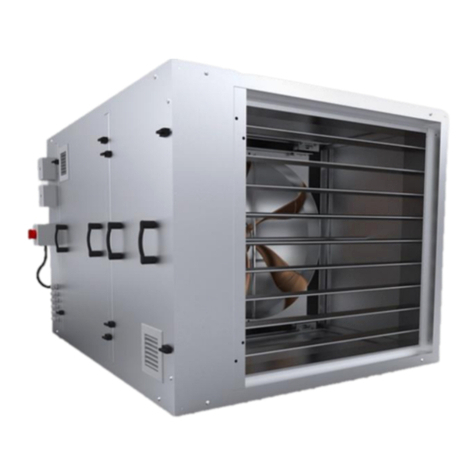
The main element of the set is the iSWAY-FC®aeration unit. iSWAY-FC®units have a
compact design while maintaining easy access for service. All products included in the set, which
are responsible for its operation (except for the elements of object automatics such as panels,
pressure sensors, etc.) are mounted inside the iSWAY-FC®casing. The components inside the unit
are installed, wired and connected already in the production plant. There is a possibility of
mounting inside and outside the building.
Version with automation cabinet SzA-FCP (with integrated frequency converter, controller
and power supply)
Fig. 4.1. Construction of iSWAY-FC®-2018 with frequency converter, controller and 24VDC power supply integrated
inside the SzA-FCP automation cabinet.

Operation and Maintenance Manual (DTR) iSWAY®Set of products
Version 1.8 of 2.2021 15
1. Housing insulated with sandwich slabs
2. Infrared heater AF OPTION
3. Device performance measuring strips LP OPTION
4. Fan
5. Braking resistor
6. Shut-off damper (supply)
7. Inspection panel
8. Smoke detector
9. Control cables and buses
entry point
10. Automatic Control Cabinet SzA-FCP
11. Pressure connection point from reference
space
12. Pressure connection point from the protection
space
13. Main switch
14. Shut-off damper with servomotor
15. Wiring duct
16. Thermostat AF OPTION
17. Ventilation grille
18. Roof for vertical version DA OPTION
19. Roof servomotor DA OPTION
20. Dowel with a screw
Fig. 4.2. Construction of iSWAY-FC-0.XX-DA®.
Detail A

Operation and Maintenance Manual (DTR) iSWAY®Set of products
Version 1.8 of 2.2021 16
4.2.iSWAY-WFC®
iSWAY-WFC®is a so-called wall device, whose construction allows for installation directly
in the wall of the building, between the space it protects and the space from which air is drawn to
secure the escape route during a fire. This reduces the space required to install the unit. The
protected space is insulated by the CDH inlet louvre, which is opened when the device is activated.
The automation cabinet Sza-FCK (power supply and control element of the iSWAY-WFC®set) for
this unit is available separately and must be connected to the unit via a cable route.
Fig. 4.5. ISWAY-WFC®-2018 construction with SzA-FCK automation cabinet (with integrated frequency converter,
controller and 24VDC power supply) separately available outside the iSWAY-WFC®unit.
31. Fan protection
32. Fan
33. Smoke detector
34. CDH-K air intake with a servomotor constituting the shut-off damper
35. Inspection panel
36. Box of the air intake and smoke detector
37. Fan box
38. Telescopic duct for wall mounting
39. Automation cabinet Sza-FCK (with frequency converter, regulator, 24 VDC power supply)
4.3. iSWAY-RFC®
iSWAY-RFC®is a so-called roof device, but it is a common name that does not restrict its
use under any circumstances. Its construction allows for installation on the roof of the building,
directly above the overpressure protected space, so that the air can be supplied directly through
an opening in the ceiling of the above space, where on the intake side there is only a roof air
intake and on the supply side an SRC damper blade isolating the protected space from external
conditions. There is also a possibility of installing air distribution on the intake and supply side in
such a way that the fan can be installed in the ventilation duct both inside and outside the
building, where isolation of the protected space from external conditions can be provided by
CDH-K intake louver or SRC-D damper. The automation cabinet Sza-FCK (power supply and
control element of the iSWAY-RFC set) for this unit is available separately and must be
connected to the unit via a cable route.

Operation and Maintenance Manual (DTR) iSWAY®Set of products
Version 1.8 of 2.2021 17
Fig. 4.6. iSWAY-RFC®-2018 construction with SzA-FCK automation cabinet (with integrated frequency converter,
controller and 24VDC power supply, separately available outside the iSWAY-RFC®unit).
39. Automation Control Cabinet SzA-FCK
40. CPD-B roof intake louver (only for roof mounting, optional)
41. Fan
42. Fan duct
43. Fan box
44. Smoke detector
45. Smoke detector housing
46. SRC-D shut-off damper with servomotor (optional)
5. Performance versions
The following subsections show the different designs and installation of iSWAY®units. The

Operation and Maintenance Manual (DTR) iSWAY®Set of products
Version 1.8 of 2.2021 18
overall dimensions of iSWAY-FC/-WFC/-RFC units can be found in Chapter 8.
5.1. iSWAY-FC®
The basic version of the iSWAY-FC®unit is a compact unit (Fig. 5.1) which enables the iSWAY-
FC®to be installed in a designated technical room (ventilation engine room) or on a roof with a
dampers of double air intake system (Fig. 5.2).
Other typical versions of iSWAY-FC®are the air intake version (Fig. 5.3) and the vertical version
only for the smallest unit iSWAY-FC-0 (Fig. 5.4).
As an option, iSWAY-FC®has introduced a system to prevent the shut-off dampers from freezing
during precipitation and low temperatures. Special low-temperature resistant seals are used to
seal the dampers.
The system is used in the refrigeration industry and a 300 W directional infrared heater system,
which is set at the factory to -2°C. When working at a temperature lower than the set temperature,
the Anti-Frost system automatically switches on. The key elements for correct operation of the
throttle valve at low temperature were painted black to absorb the maximum amount of infrared
radiation. The remaining iSWAY-FC®interior components are left in bright colours to reflect the
radiation and direct it to the essential elements, which enhances the infrared beam.
To achieve the declared capacity of the air handling fan, a straight section of duct with a minimum
length equal to the diameter of the fan used must be provided directly behind the unit on the supply
side. If local technical conditions allow it, a 1 m long straight line is recommended.
Fig. 5.1. ISWAY-FC®basic unit.
Air flow direction –intake iSWAY FC
Air flow direction –outlet iSWAY FC

Operation and Maintenance Manual (DTR) iSWAY®Set of products
Version 1.8 of 2.2021 19
Fig. 5.2. ISWAY-FC®with two air dampers (primary and back-up, components of the two air intake system) - top view.
Fig. 5.3. iSWAY-FC®version with air intake.
Auxiliary intake damper
Main intake damper
Air flow direction
Recommended 12 meters

Operation and Maintenance Manual (DTR) iSWAY®Set of products
Version 1.8 of 2.2021 20
Fig. 5.4. Vertical version with closed canopy for the smallest iSWAY-FC®type 0 device.
Fig. 5.5. Vertical version with open canopy for the smallest iSWAY-FC®type 0 device.
Detail A
Detail A
Other manuals for iSWAY-FC
1
This manual suits for next models
2
Table of contents
Other SMAY Fan manuals
Popular Fan manuals by other brands

Sealey
Sealey HVD30 quick start guide

Hydor
Hydor HEB Installation and maintenance instruction

HEPACART
HEPACART HEPAFORCE HFAIR2100 Installation, operation and maintenance manual

Prominence Home
Prominence Home Almadale 50330 owner's manual

Chatsworth Products
Chatsworth Products 40972-001 installation instructions

Maico
Maico PPB 30 O Wiring diagram