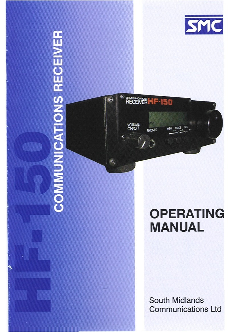
SMC Networks HF-150 User manual

1
Getting Started
HF-150
COMMUNICATIONS RECEIVER
OPERATING
MANUAL
South Midlands
Communications Ltd

PR-150
For add selectivity
and rejection of
unwanted signals
AP-150
Digital Audio
Processor for
enhanced audio
output
IF-150
Computer RS232
Serial interface for
ease of control
and auto
frequency
selection
KPAD-2
Keypad for ease of
remote access to
frequency and
mode selection
HF-150 ADD ON ACCESSORIES

HF-150 - Users Manual 3
Getting Started
Contents
Introduction . . . . . . . . . . . . . . . . . . . .4
Getting started
Aerials . . . . . . . . . . . . . . . . . .5
Active Antenna . . . . . . . . . . .7
Connections . . . . . . . . . . . . .8
Types of signal . . . . . . . . . .10
Controls
Front Panel . . . . . . . . . . . . .14
Rear Panel . . . . . . . . . . . . . .16
Operating the HF-150
Volume . . . . . . . . . . . . . . . .18
Modes . . . . . . . . . . . . . . . . .18
Tuning . . . . . . . . . . . . . . . . .19
Keypad . . . . . . . . . . . . . . . .21
Aerial switch . . . . . . . . . . . .23
Memories . . . . . . . . . . . . . .24
Accessory kit . . . . . . . . . . . . . . . . . .25
Care of your receiver . . . . . . . . . . . .26
General notes . . . . . . . . . . . . . . . . . .27
Technical information . . . . . . . . . . .28
(c) 1999 South Midlands Communications Ltd

HF-150 - Users Manual
4
Getting Started
The term "Communications Receiver" was originally used in its quite literal
sense to describe a radio receiver which was part of a point to point
communications link. These radio links were normally manned by trained
operators, and Morse Code was the usual method of transmitting information.
Because of the specialist nature of the system and the fact that the operators
were technically trained the communications receiver itself was quite often a
complex piece of equipment.
Over the past twenty or so years, a marked change has taken place in short
wave spectrum occupancy and there has been a considerable increase in
broadcasting, air traffic control, news agency transmissions and so on. The
interest in listening generated by this spread of activity has led to a demand
amongst the general public for receivers which will enable them to keep in
touch with world affairs by short wave radio.
Clearly, these users of receivers are more interested in listening than in the
technicalities of operating the equipment and this in turn has resulted in the
introduction of simpler receivers. However, simplicity of operation has often
been accomplished by a compromise in actual performance, and the results
obtained from some of these simple receivers have been quite disappointing.
As our founder once remarked, "Some receivers are rather like a chocolate
eclair; Wonderful to behold but containing little of substance."
The design and development of the HF-150 was based on
straightforward objectives:-
* To obtain sufficient RF performance for the receiver to operate in
crowded short wave bands with many strong signals.
* To combine complete control of a necessarily complex piece of
equipment with easy operation for the user.
* To achieve both the previous objectives within a compact, portable
package at a reasonable price.
We believe that these stated goals have been reached, and that the HF-
150 receiver represents a truly new approach to meeting the demands of the
serious short wave listener.

HF-150 - Users Manual 5
Getting Started
Aerials and Earths.
Operating the HF-150 is described in the next two sections of this manual, but
you may well ask "What is a suitable aerial?" The receiver has been designed
to work well with a simple long wire aerial, about 10 to 30 metres long. This will
provide good results on most frequencies covered by the set, but if your
interest is in a particular band, such as the 49 metre broadcast band, you may
wish to consider a dipole aerial tuned to that frequency. Do not be dazzled by
the idea of putting up the longest wire in the whole world. This will bring you to
grief, because you will probably overload the input stages of the receiver with
signals from strong broadcast transmitters, with a resultant increase in
background noise.
Where space is at a premium a short wire aerial (a few metres long, maybe
indoors) or a whip aerial can be used. The HF-150 includes a whip antenna
input circuit which optimises its performance with short aerials or in weak signal
areas. However reception, particularly of lower frequencies (long and medium
wave), will be compromised by a short aerial and the receiver will be more
susceptible to locally generated interference.
A good aerial deserves a good earth connection and a ground system
specifically for the receiver is always an advantage. This can be made fairly
simply by driving a metal post into the ground to a depth of about 1 metre and
connecting it to the black ground terminal on the rear panel of the receiver. With
the exception of the 110V model, the mains power supply for the HF-150
provides an earth connection from the receiver to the mains earth system. This
is often adequate for most locations, but in some situations can result in
excessive interference from other mains appliances, which a separate earth
system would avoid.
Long wire aerials should connect to the red terminal on the rear panel of the
HF-150, whereas whips or short wire aerials should connect to the centre of the
co-axial connector - a 4mm plug can be used to connect wires into this - and
the antenna select switch set to the WHIP position. Any aerial systems that
connect to the receiver by co-axial cable (active aerials and dipoles) should use
the co-axial connector with the selector switch in the NORM position.

HF-150 - Users Manual
6
Getting Started
The Long wire Aerial.
This is the simplest type of outdoor aerial system, and is very effective for
general short-wave listening. It consists of a single, insulated wire erected with
a horizontal top section and a down lead from one end going to the receiver's
wire aerial input terminal. The wire should be erected as high as possible, and
as far away as possible from other structures or overhead power lines. It can
often be suspended between two buildings or between a building and a tree.
Insulators should be used as shown, and the lead in wire should also be
insulated. The drawing shows a long wire in the form of an "Inverted L," but
many other configurations can be used, such as a slanting wire leading directly
to the receiver.
Other Aerials.
There are several ready-made vertical aerial systems on the market, and they
will provide an easy to erect system occupying very little ground area. They are
normally designed to work over quite a narrow frequency range (typically
amateur radio bands), and for general listening a simple wire will often give
better results.
Active aerials attempt to overcome the problems of very short aerials by placing
a high-impedance amplifier between the antenna and the receiver. The
amplifier must be near to the aerial, so often power is fed to it along the co-axial
cable connecting it to the receiver. The active aerial is very compact, often little
more than a metre long, but a poorly designed active aerial can badly
compromise the receivers performance due to the amplifier overloading in the
presence of many strong broadcast signals.
SMC P2
INSULATORS
LENGTH = 10 to 30m
AERIAL GROUND
RECEIVER
CONNECTIONS
TO AERIAL SOCKET
TO EARTH

HF-150 - Users Manual 7
Getting Started
HF-150 MARINE RADIO
IMPORTANT
If you have purchased the Marine Radio version of the HF-150 you should be
aware of the following.
The HF-150 is sent out for normal passive aerial use.
You can use this radio with an active aerial, which will require a 12V DC supply
at the aerial socket.
To make the socket active.
1 Remove the four base fixing screws
2 Remove the bottom cover
3 Connect jumper to bridge the connector at the rear of the PCB.
WARNING: THIS WILL SUPPLY +12VDC TO THE AERIAL SOCKET AND THE
JUMPER SHOULD BE REMOVED FOR NORMAL PASSIVE AERIAL USE
We strongly advise you to label the aerial socket clearly to inform users that
12VDC is present at this outlet.
South Midlands Communications Ltd will accept no responsibility or liabity for
the incorrect use of this feature.
If in doubt consult your dealer.
Suitable Active Aerial
The AA-150M optional accessory is a high performance active antenna which
has been specially designed for the marine version of the HF-150(M).
This aerial has been carefully optimised to match the high performance of the
HF-150M to prevent an overload of signal.
The modification details above will need to be set for use with this aerial.

HF-150 - Users Manual
8
Getting Started
Connections.
Power Supply.
The HF-150 receiver can operate from its internal batteries or from an external
DC supply of between 10 and 15 volts. The absolute maximum supply is 16
volts, and if this is exceeded damage may occur to the receiver. The supply
polarity is negative ground only, and although reverse polarity protection is built
in it is wise to ensure that any supply is correctly connected. Be sure that the
receiver power switch is OFF before plugging in or unplugging the power
connector.
In most countries, the HF-150 will be supplied with a small 12 volt regulated
power unit which is designed to operate from the local mains power.
Remember that this supply will be operating all the time that it is connected to
the mains outlet, and it is a wise safety precaution to disconnect it from the
mains supply when the receiver is not in use.
The HF-150M marine receiver is supplied with a 12 volt lead only.
In the United Kingdom the power supply is fitted with a three-core mains lead,
and the earth connection (yellow/green) is connected to the negative (ground)
terminal of the receiver. This provides a reasonable earth connection for the
receiver, but in some cases, where the mains-born interference is prominent, it
will be necessary to provide the receiver with a good RF earth, either in addition
to the mains earth or in some cases instead of it. If the receiver is used with any
other mains power supply it should be able to comply with BSI standards
relating to Class 2 insulation.
Either alkaline-manganese batteries or rechargeable nickel-cadmium batteries
can be fitted to the receiver if it is to be used away from a source of power.
Rechargeable batteries will charge within the set if it is connected to a 12 volt
power source and switched off. For this reason we recommend that non-
rechargeable ones are removed from the set if it is used for more than a few
hours on an external supply.
Rechargeable batteries will run the set for three to four hours on a full charge,
and require about 16 hours to charge fully from a 12 volt supply. Charging time
can be longer that this without damaging batteries.

HF-150 - Users Manual 9
Getting Started
External Loudspeaker.
A small internal loudspeaker is provided in the HF-150 so that it is self
contained, but although it can provide reasonable all round audio quality,
clearly in the limited space available compromise has to be made. You will find
that if the volume control is set to a high level there may be some audio
feedback caused by vibration induced by the internal loudspeaker. If it is
necessary to operate the receiver at high audio levels, or you want better
quality reproduction the use of an external loudspeaker is recommended.
Because the HF-150 is capable of giving a high quality audio signal, we
suggest you use a good external loudspeaker, a small bookshelf type Hi-Fi unit
is satisfactory. We can provide a suitable unit as an optional accessory with the
correct connecting lead for the HF-150. Any external loudspeaker should have
an impedance of 4 ohms or greater.
Record Output.
Many keen listeners like to tape record any interesting stations they hear, and
a low level audio output has been provided for this purpose.
The REC OUT socket accepts a 3.5mm mono jack plug and provides a level
suitable for feeding into the line input of most tape recorders or amplifier
systems. An attenuating resistor should be added in the lead if feeding directly
into the microphone input of a cassette recorder. The output level at this socket
is not affected by the volume control, so that the loudspeaker can be used to
monitor whilst recording.
The record output can also be used for driving most types of receiver ancillary
equipment such as RTTY, facsimile or Morse decoders. The output level is
about 200m V from a source impedance of 5k ohms.

HF-150 - Users Manual
10
Getting Started
Types of Signal.
The HF-150 is equipped to receive most types of transmission likely to be found
within its tuning range, and although most users will be familiar with these, here
are some brief notes on this topic that may be useful to beginners.
AM (Amplitude Modulation).
This was the earliest method used of audio modulation of an RF carrier wave,
and is still almost universally used for long, medium and short wave
broadcasting. An AM signal is fairly easy to tune in, and given a reasonable
signal strength, the receiver may not need to be spot on in frequency. However
when conditions are poor, AM can be difficult to resolve - one particular
problem is frequency selective fading and this is discussed later.
AM Selectivity.
A radio signal occupies a certain portion of the radio spectrum which is known
as its bandwidth. The bandwidth of an AM signal is twice its highest modulation
frequency, and because of this broadcasters are restricted to transmitting audio
frequencies below 5kHz so that they do not occupy too much spectrum. In the
long and medium wave broadcast bands, station frequencies are separated by
9kHz (10kHz in the USA) so there is little or no overlap of adjacent signal
bandwidths. In the short wave bands however, the stations use a nominal 5kHz
spacing, and some broadcasters do not abide by any rules at all, so there is
considerable signal overlap.
The HF-150 is provided with two different AM modes with different filter
bandwidths because of this very problem. If you are receiving a strong signal
in a clear part of the radio spectrum then you can use the standard AM mode
with a 7kHz filter and obtain the best fidelity. The stronger and closer adjacent
stations are, the narrower the filter you will need, and the more muffled the
sound will be because high frequencies are removed. The narrow AM mode
uses a 2.5kHz filter and is necessary in severe conditions, but it is really only
suitable for speech reproduction. When AM mode is chosen you may find that
reception of a station is improved by tuning the receiver slightly above or below
its stated carrier frequency. This is quite a useful technique if there is a strong
adjacent signal that you don't want. As long as the carrier signal is within the
receiver's filter then all will be well, but if you tune too far or select a narrower
filter then the signal will become distorted.
HF-150 - Users Manual 11
Getting Started
SSB (Single Sideband).
An AM signal can be considered as a carrier wave combined with two identical
sidebands which contain the modulating audio signal. It is possible to remove
one of the sidebands without losing any vital information, and immediately
halve the bandwidth occupied by the signal. In practice the carrier wave is also
removed (or partially suppressed) to improve transmission efficiency, and the
result is a single sideband transmission.
SSB transmissions are used extensively for voice communication, particularly
to aircraft and shipping, and also by radio amateurs. It is possible to use either
of the two initial sidebands of a signal, so there are two distinct types of SSB
transmission; Upper Sideband (USB) where the sideband frequency is above
the carrier frequency, and Lower Sideband (LSB) where it is below. Nearly all
commercial transmissions are USB, as are amateur transmissions at
frequencies above 10MHz. At frequencies below 10MHz radio amateurs use
LSB by convention.
To receive an SSB transmission, the receiver must reinsert the missing carrier
signal. If this is not done the signal will sound just like Donald Duck - try
listening to an SSB signal in AM mode for this effect. For correct reception the
receiver should be tuned exactly to the carrier frequency, but for speech an
error of 50Hz either way will not be serious. The HF-150 has a very slow tune
rate on its SSB modes to facilitate accurate tuning, but you will need a steady
hand. The pitch of the received voice will change as you tune through the
signal, buy only at one tuning position will it sound like a natural voice. A
2.5kHz bandwidth filter will just accommodate the audio frequencies used for
voice transmission, and this is the filter used for SSB reception.
CW (Continuous Wave, i.e. Morse).
Morse code is usually transmitted by interrupting a single carrier wave, and it
occupies a very narrow bandwidth. In terms of ability to get a message through
under difficult propagation conditions Morse code is one of the most efficient
method, although modern error-correcting digital data systems are also very
good. CW signals are received in the same way as SSB signals, with the carrier
inserted in the receiver producing a beat note with the incoming signal, and
either the LSB or USB modes can be used. Often the one chosen is a matter of
operator preference, or one which best rejects any interfering signals.

HF-150 - Users Manual
12
Getting Started
RTTY (Radio Teletype).
The method of sending teleprinter messages by HF radio link is to use
two closely spaced tone signals, transmitting one or the other to send binary
data. Each teleprinter character is encoded into a different sequence of tones
which are transmitted in a bewildering combination of different speeds, tone
shifts, and code types. RTTY signals are tuned in SSB mode on a receiver, but
require a special terminal unit to decode and display the actual text.
FAX (Facsimile).
Pictorial information (often meteorological data) is transmitted over HF
radio links for reception by shipping. As with RTTY, a special facsimile decoder
and display or printer is required for its reception. Several home computers
support software packages for decoding FAX and RTTY signals.
FM (Frequency Modulation).
FM transmissions in the HF spectrum are usually limited to the 27MHz
Citizens Band and the 28MHz amateur band. The HF-150 does not offer an FM
mode to directly receive these signals, but it is usually possible to resolve them
in AM mode with the receiver off-tuned by some 3kHz above or below the
transmission frequency. This is technically known as 'filter slope detection'.
AM Propagation and Fading.
During AM signal reception it is possible to experience severe fading problems,
particularly after nightfall. This is mainly due to the signal reaching the receiver
by several different paths from the transmitter, and it is most common after dark
because this is when the ionosphere reflects most HF radio signals. Fading
occurs when the signals arrive at the receiver in antiphase (having travelled
different distances) and then cancel each other out. This will only occur at a few
specific frequencies at any one instant, hence the term frequency selective
fading.
If a selective fade reduces the carrier level of an AM signal, but leaves the
sideband levels unaltered, a receiver with a conventional AM detector will not
be able to correctly reproduce the signal, and the output will be distorted.
There are two techniques that can be used to improve the situation; ECSS, and
Synchronous (or Phase-Locked) AM detection.

HF-150 - Users Manual 13
Getting Started
ECSS (Exalted Carrier, Selectable Sideband).
The ECSS technique makes use of the fact that with a good, selective receiver,
capable of resolving SSB, an AM signal can be passed through the SSB filter
which is only wide enough to allow one sideband through. The filter must
attenuate the carrier signal by at least 20dB for this technique to work with any
success.
The receiver can be used in the SSB mode with the incoming AM carrier tuned
to zero beat, and the accompanying sideband treated as a true SSB signal.
Either the upper or lower sideband can be selected using either USB or LSB
mode, so interfering stations can often be eliminated. The improvement in
intelligibility is often dramatic, and it is well worth trying out ECSS and
developing the ability to use it. The HF-150 when used with its USB or LSB
modes is ideally suited to ECSS reception.
AMS (Synchronous AM)
The difficulty in receiving music signals with the ECSS method is that it is very
difficult to match the receivers injected carrier exactly with the frequency of the
incoming carrier. Any difference results in a frequency shift of the audio signal,
and the consequent loss of harmonic relationships.
The synchronous AM detector in the HF-150 uses a narrow deviation phase-
locked oscillator to replace the incoming AM carrier. When locked, this
oscillator is at exactly the same frequency as the carrier signal, and does not
have to rely on absolute receiver tuning accuracy. Incoming carrier level
changes make no difference to the signal detection provided that there is some
carrier for the oscillator to lock on to.
A total of four filter arrangements are available on the HF-150 in synchronous
AM mode: - upper sideband only, lower sideband only, both sidebands (for
better resistance to fading if there are no interfering signals) and a special "Hi-
Fi" mode which gives extended frequency response and very low distortion for
listening to clear, strong stations.

HF-150 - Users Manual
14
Controls
Front Panel Controls.
1) Memory mode flag: This segment of the display is shown when the
receiver is in memory mode. The keypad and tuning knob select memory
numbers, and the three control buttons operate as MEMORY, RECALL and
STORE.
2) Frequency display: The 5-digit liquid crystal display normally shows
the receiver's tuned frequency, with a decimal point in between megahertz and
kilohertz sections. At frequencies below 1.7MHz, (i.e. medium and long
wavebands) the display shows kilohertz with no decimal point. Additionally the
display is used to indicate mode and memory number when appropriate
control buttons are pressed.
3) Tuning knob: For tuning the receiver and selecting memories. The rate
of tuning is altered according to the receiver's mode and the speed of rotation
of the tuning knob. Memory numbers are changed by turning the tuning knob
when the receiver is in memory mode.
12.095
COMMUNICATIONS
RECEIVER
VOLUME
ON OFF PHONES
MEM
MEM MODE FAST
RCL STO
2
87654
31
HF-150

HF-150 - Users Manual 15
Controls
4) Volume control: Combined with the on/off switch, the volume control
operates for the internal and external loudspeakers and the headphone output.
The record out jack is unaffected by the volume setting. The on/off switch
controls receiver power and battery charging if NiCd batteries are fitted.
5) Headphone jack: An output for use with personal headphones - the
receiver's internal speaker is disconnected when headphones are plugged in.
A 6.3mm mono or stereo plug is suitable for the headphone output, and
'phones fitted with a 3.5mm plug can be used with a suitable adapter. Stereo
headphones will operate in mono.
6) Memory button: Pressing the MEM button changes the receiver
between memory and tuning modes. In memory mode the memory flag (1) is
shown and the tuning knob and keypad select memory numbers. When in
memory mode, pressing MEM, RCL or STO will revert to tuning mode.
7) Mode button: The MODE button operates when the receiver is in tuning
mode, and allows selection of the type of reception. The display shows a
mnemonic representing each mode, and the other two buttons can be used to
step forwards or backwards through the eight available modes. See page 15
"Modes". Reception changes as soon as a new mode is selected. The display
will revert to frequency when MODE is pressed a second time, or after about 7
seconds without any buttons being pressed, or if the tuning knob is rotated.
8) Fast tune button: If the receiver is in tuning mode, pressing the FAST
button speeds up the tuning rate of the main tuning knob. The two right-hand
display digits are blanked, and the display is altered in 100kHz steps. The
receiver is tuned to the newly selected frequency when the FAST button is
pressed again.

HF-150 - Users Manual
16
Controls
Rear Panel Controls and Connections.
9) Battery holders: The HF-150 needs a total of eight AA size batteries to
operate - 4 cells in each of the two battery holders. The Battery drawers are
released by squeezing together the lugs on either side of the holder. When
replacing a drawer make sure that it is pressed fully in so that the cells are
suitable, but all eight cells must be of the same type. Standard zinc/carbon
cells are not recommended because of the risk of leakage.
Nickel/cadmium cells will recharge in the receiver provided that it is connected
to a 12volt supply and the volume/power switch is in the OFF position. Non-
rechargeable cells should be removed from the receiver if it is connected to an
external supply for more than a few hours.
10) Keypad jack: For connection of the optional keypad unit, allowing
direct entry of frequencies and memory numbers.
11) Coaxial/Whip aerial connection: This SO-239 type connector provides
the receiver input from aerials terminated with coaxial cable (nominally 50
ohms impedance) or for the whip aerial supplied in the accessory kit. The
select switch (12) determines the function of this socket.
HF-150
131211
9
10 14 15 16 17

HF-150 - Users Manual 17
Controls
12) Aerial select switch: This three-position switch controls the operation of
the whip aerial amplifier and the RF attenuator. In the WHIP position the SO-239
socket (11) is intended for a whip aerial or a short wire (just a few metres) and
the spring terminal (13) is disconnected. In the NORM and ATTEN positions
both aerial input are operative, with signal strengths reaching the receiver
being reduced in the ATTEN position.
13) Wire aerial connection: The red spring terminal is for connection of
long wire aerials and has a nominal impedance of 600 ohms. This input is
disconnected from the receiver when the aerial select switch (12) is in the WHIP
position.
14) Ground connection: The black spring terminal is connected to the case
of the receiver and serves as the connection to an RF earth if this is provided.
See page 3 "Aerials and Earths".
15) Record output jack: A fixed level audio signal is available from this
socket that is unaffected by the volume control setting. The level (about
200mV) is suitable for feeding into the line input of most tape recorders and for
driving FAX, RTTY, etc decoders. If the signal has to be fed into the microphone
input of a tape recorder (in the absence of a line input) then a series resistor
should be inserted in the connection to reduce the signal level.
16) External loudspeaker jack: For connection of an external loudspeaker
of 4 to 8 ohms impedance. Inserting a plug into this jack will disconnect the
internal loudspeaker, and this output is disconnected by insertion of a plug into
the front-panel headphone jack.
17) Power input connection: An external DC power supply is connected
here if the set is not to run on its internal batteries. If you are not using the
supplied mains adapter then check that the supply polarity is correct (positive-
inner, negative-outer) and that the voltage is between 10 and 15 volts. Current
requirement is about 120mA rising to 300mA at high volume settings.

HF-150 - Users Manual
18
Controls
Operating the Receiver.
Volume/Power.
The volume control affects the level of the sound from the loudspeaker or fed
to the headphones. The signal from the record out socket on the rear of the
receiver is not altered. It also functions as a power switch, and turning it fully
counter-clockwise will turn the receiver off. If you are running the receiver from
its mains adapter then the adapter will still be powered even if the receiver is
turned off, and you should switch off or unplug the adapter when not in use.
If rechargeable batteries are fitted to the HF-150 then they will charge if power
is supplied to the receiver when it is switched off. The batteries will fully charge
in about 16 hours from a completely discharged condition. A limited amount of
over-charging will not harm the batteries, but you should avoid charging for
periods longer than 3 days. When the receiver is switched on, a small trickle-
charge is supplied to the batteries which will maintain a full charge against
gradual leakage.
When running the receiver from batteries, a message LoPr (low power) will be
shown when the battery voltage falls below a usable level. The tuning and
push-button controls will stop operating but the receiver may still work for a few
minutes. Replace the batteries or run the receiver from an external supply to
restore normal operation. It is common for the low power message to display
momentarily when the receiver is switched off.
Modes.
There are three types of reception available on the HF-150: - Single sideband,
AM and Synchronous AM (AMS). The eight modes selectable on the receiver
choose various filter combinations within these three types. Mode selection is
made by pressing the MODE button on the front panel of the receiver and then
using the other two buttons to step backwards or forwards through a choice of
modes, shown by mnemonics on the display. When a mode has been selected,
it will remain displayed, and can be further changed, for about 7 seconds
before the display reverts to frequency. Pressing the MODE button or turning
the tuning knob during this period will immediately cause the display to revert
to frequency. The mode selection sequence is shown over the page.

HF-150 - Users Manual 19
Operation
Type Display Mode Filter Bandwidth
SSB LSb Lower sideband 2.5kHz
Usb Upper sideband 2.5kHz
AM A AM, wide filter 7kHz
An AM, narrow filter 2.5kHz
AM Sync ASd AMS, double sideband 7kHz
ASF AMS, "hi-fi" mode 7kHz
ASL AMS, lower sideband only 2.5kHz
ASu AMS, upper sideband only 2.5kHz
Forward selection sequence (right-hand button) : -
LSb - > USb - > A - > An - > ASd - > ASF - > ASL - > ASu - > LSB etc.
Backward selection sequence (left-hand button) : -
LSb < - Usb < - A < - An < - ASd < - ASF < - ASL < - ASu < - LSB
Tuning.
The HF-150 is tuned with a single rotary control (which drives a digital shaft
encoder) giving continuous tuning over the whole of the receiver's range. There
are no separate tuning bands on the HF-150, but for convenience a fast tune
mode is provided to tune in 100 kilohertz steps to a frequency near the one of
interest.
The frequency readout on the HF-150 is at the true carrier frequency in all
modes of reception. It is at the centre of the filter passband in AM mode, and
at the reinjected carrier frequency in USB and LSB modes. Although the
frequency display mode changes in 1 kilohertz steps the receiver is actually
tuned in much smaller steps - sufficiently small for tuning to appear continuous.
The rate at which the receiver tunes when the tuning knob is rotated depends
on the mode selected and on the speed of rotation of the knob. When the
tuning knob is rotated rapidly the tuning rate increases. This allows a slow
tuning rate for precise signal resolution coupled with the ability to reach the
required frequency quickly. You may find at first that the receiver apparently
jumps in frequency when you are trying to tune a signal. This is because you
have moved the tuning control quickly or in a jerky fashion and the receiver has
increased its tuning rate. A smooth action will cure the problem, and will make
tuning the HF-150, and any other receiver, much easier.

HF-150 - Users Manual
20
Operation
The tuning rates adopted by the HF-150 are shown in the table below: -
Mode Normal tune rate Fast tune rate
Tuning step kHz per rev
LSB, USB 8Hz 1.6 8 times faster
AM, AMn 60Hz 12 6 times faster
AMSd, AMSf 8Hz 1.6 Switches to AM
AMS1, AMSu 8Hz 0.8 Switches to AM
When the operating frequency limits of the HF-150 are reached, tuning will
stop. There are no mechanical stops on the tuning knob, but you will notice that
the frequency display stops changing. The lower tuning limit is 30kHz and the
upper limit 29.999MHz on a standard model, but these are changed to 150kHz
and 29.999MHz for the German market. Unlike some receivers, the HF-150
does not wrap-around between its highest and lowest frequencies.
Fast Tuning Mode.
Pressing the FAST button blanks the two rightmost digits of the frequency
display and allows the tuning knob to rapidly change the remaining three digits.
The receiver remains tuned to its previous frequency during this operation, but
is tuned to the new frequency when the FAST button is pressed a second time.
The frequency set by the fast tune mode retains the setting of the blanked digits
from the previous receiver frequency, so an inadvertent press of the FAST
button can be cancelled by simply pressing the button again without turning
the tuning knob.
Tuning in Synchronous AM Mode.
The tuning of the receiver in synchronous AM mode is more critical than in the
normal AM modes, because the signal has to be within the lock range of the
synchronous detector. To aid tuning, a slow tuning rate is provided in all four
AMS modes. It is difficult to 'search tune' in AMS mode (i.e. tune through a
selection of frequencies looking for a particular signal) so the receiver
automatically switches to normal AM mode whenever the tuning knob is rotated
quickly. When the tuning knob is not moved for about one second the receiver
will return to its previous AMS mode.
Other manuals for HF-150
1
Table of contents
Other SMC Networks Receiver manuals

SMC Networks
SMC Networks EZ-Stream SMCWMR-AG User manual

SMC Networks
SMC Networks SMCWMR-AG User manual

SMC Networks
SMC Networks WMR-AG - annexe 1 User manual

SMC Networks
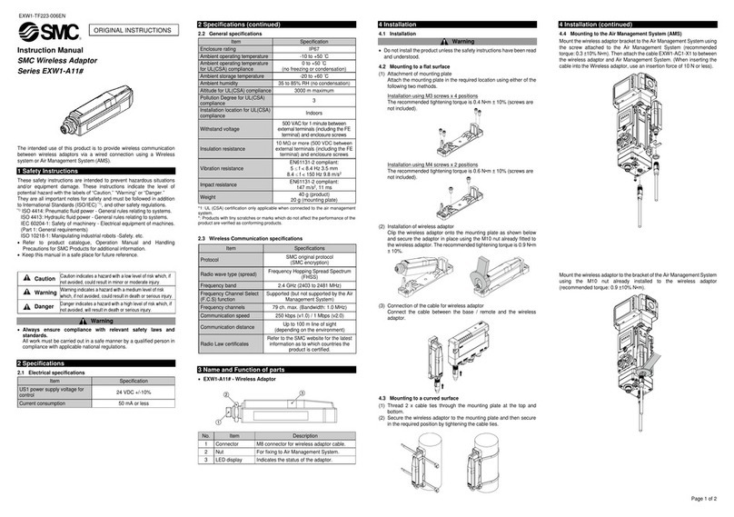
SMC Networks EXW1-A11 Series User manual

SMC Networks
SMC Networks SMCWMR-AG User manual

SMC Networks
SMC Networks EXW1-A11N-X1 Series User manual

SMC Networks
SMC Networks EXW1-A11N-X1 User manual

SMC Networks
SMC Networks HF-150 User manual