Hi-Target V60 User manual

V60 GNSS RTK System Operation Instruction
Preface
Introduction
The introduction is applicable to Hi-Target V60 products. V60
is a new type of GNSS receiver used for measurement. The
introduction describes how to install, set and use V60
products.
In order to help you better use Hi-Target series products,
Hi-Target suggests you carefully reading the instruction. If you
are unfamiliar with V60 products, please refer to
www.hi-target.com.cn/en/
Tips for safe use
Note: the contents here generally are special
operations, needing your special attention.
Please read the contents carefully.
I

Introductions to Receiver
Warning: the contents here generally are very
important. In case of failing to operate
based on warning contents, it will damage
the machine, lose the data, break down the
system and endanger personal safety.
Exclusions
Before using the products, please carefully read the operating
instruction, and it will help you better use the product.
Hi-Target Surveying Instrument Co., Ltd will not assume the
responsibilities if you fail to operate the product according to
the requirements in operating instruction, or operate the
product wrongly because of failing to understand the operating
instruction.
Hi-Target is committed to constantly perfect product functions
and performance, improve service quality and reserve the
rights to change the contents in operating instruction without
separate notice.
II

V60 GNSS RTK System Operation Instruction
We have checked the consistency between contents in
instruction and software & hardware, without eliminating the
possibility of deviation. The pictures in operating instruction
are only used for reference. In case of inconformity with
products, the products shall prevail.
III

Introductions to Receiver
Content
Product Introduction .................................... 1
Preface ..................................................2
Product Characteristics ..................................3
Cautions for Use .........................................4
Introductions to Receiver................................ 6
Receiver Appearance ......................................7
Control Panel ............................................7
Upper Cover ..............................................8
Bottom Cover .............................................9
Five-core and Eight-core Sockets ........................11
Batteries ...............................................13
Environmental Requirements ..............................14
Electronic Jamming ......................................14
Elementary Operation ....................................16
Power Supply ............................................17
Control Panel ...........................................21
Key Functions ...........................................23
Start and Stop Receiver .................................29
SIM card/USIM Card ......................................29
Static Data Storage .....................................31
RTK Data storage ........................................34
Reset receiver ..........................................35
Formatting Receiver .....................................35
IV

V60 GNSS RTK System Operation Instruction
Firmware ................................................37
Static Collection and Data Transmission ...................38
Preface .................................................40
Static Measurement ......................................40
U Disk Data Download ....................................42
Operations of Static Management Software ................43
Technical Parameters ....................................46
GNSS Part ...............................................47
Receiver Precision ......................................47
Interface ...............................................48
Physical characteristics ................................48
Environment .............................................49
Socket and Main Accessories ..............................50
Preface .................................................51
Y-type Data Cable .......................................51
Annexed Table 1 Instructions of Indicator Lights in Control
Panel..................................................52
V


V60 GNSS RTK System Operation Instruction
Product Introduction
This chapter describes:
■ Preface
■ Product characteristics
■ Cautions for use
C
H
A
P
T
E
R
1
1

Introductions to Receiver
Preface
V60 is a new type of GNSS receiver used for measurement
pushed forward by Hi-Target recently. The receiver is provided
with 1G mass storage and one SD card extendable slot, which
can record static data in forms of GNS and Rinex
simultaneously. With brand new appearance design and
optimized internal structure, the product extends the design
style of previous products, making it cope with various
complex conditions outside. The product has self-diagnostic
function, which can intelligently monitor the immediate
situations of various software and hardware during operation
process; the product adopts brand new high-precision RTK
system on color liquid crystal screen with modular design. The
product boasts stable and GPRS network module, which can
exchange difference transport module according to customer
requirements and seamlessly connect CORS network systemin
main manufactures.
Warning: the instruction represents no standard
configuration. The articles within the box
can be adjusted according to different user
requirements. The specific configuration
shall be subject to the outgoing list upon
purchasing. The suggestions before using
the machine: check whether the product
package is damaged; please open the
package carefully and confirm whether the
articles are consistent with outgoing list; in
2

V60 GNSS RTK System Operation Instruction
case of loss or damage in the product and
its accessories, please immediately contact
with local office or dealers; please carefully
read the operating instruction before
carrying, transporting and using the
product.
Product Characteristics
◇Obtain the CE0890 certification
◇Apply multi-satellite system and multi-frequency
GNSS unit; support BDS, GPS and GLONASS
system navigation and positioning
◇Internally install 1G mass memory; support SD card
data storage, 32GB as a maximum
◇Internally install a transceiver; then base and rover
can be exchange completely
◇GPRS Communication function:
◇With high-capacity lithium battery, the product can
meet long-time operation requirements outside
◇Intelligent voice
◇Intelligent self-diagnostic function
◇Function of accelerating and express upgrading
◇Static data are stored in two formats (*.GNS /
RINEX Data)
3

Introductions to Receiver
◇128x64 resolution; 1.54-inch liquid crystal display
The user can flexibly set the instrument and observe
the operations of instrument through display
Cautions for Use
As a precise instrument, the receiver shall be used and
maintained carefully regardless of the materials resistant to
chemical agent and impact.
Warning: the receiver shall be in stipulated
temperature range upon using and storage.
The detailed requirements are shown in
Chapter V: Technical Parameters —>
Environment.
In order to guarantee the quality of continuous tracking
observation and satellite signals, it is required that the
overhead observation station shall be open, without flaky
barriers above 15° elevating angle; in order to diminish the
interference of electromagnetic wave to GNSS satellite signals,
the observation station shall be free form strong
electromagnetic wave within the range of 200m, such as
television tower, microware station and high-voltage
transmission line; in order to avoid or reduce multipath effect,
the observation station shall be far away from the terrain and
ground features with strong reflection against electromagnetic
wave signal, such as high-rise buildings, waters, etc.
Changes or modifications not expressly approved by the party
4

V60 GNSS RTK System Operation Instruction
responsible for compliance could void the user’s authority to
operate the equipment.
This equipment has been tested and found to comply with the
limits for a Class B digital device, pursuant to Part 15 of the
FCC Rules. These limits are designed to provide reasonable
protection against harmful interference in a residential
installation. This equipment generates, uses and can radiate
radio frequency energy and, if not installed and used in
accordance with the instructions, may cause harmful
interference to radio communications. However, there is no
guarantee that interference will not occur in a particular
installation.
If this equipment does cause harmful interference to radio or
television reception, which can be determined by turning the
equipment off and on, the user is encouraged to try to correct
the interference by one or more of the following measures:
-- Reorient or relocate the receiving antenna.
-- Increase the separation between the equipment and receiver.
-- Connect the equipment into an outlet on a circuit different
fromthat to which the receiver is connected.
-- Consult the dealer or an experienced radio/TVtechnician for
help.
5

Introductions to Receiver
Introductions to Receiver
This chapter describes:
■ Receiver appearance
■ Control panel
■ Upper cover
■ Bottom cover
■ Five-core and eight-core sockets
■ Batteries
■ Environmental requirements
■ Electronic jamming
C
H
A
P
T
E
R
2
6

V60 GNSS RTK System Operation Instruction
Receiver Appearance
The product appearance is divided into four sections, upper
cover, bottom cover, guard circle and control panel.
Figure 2-1
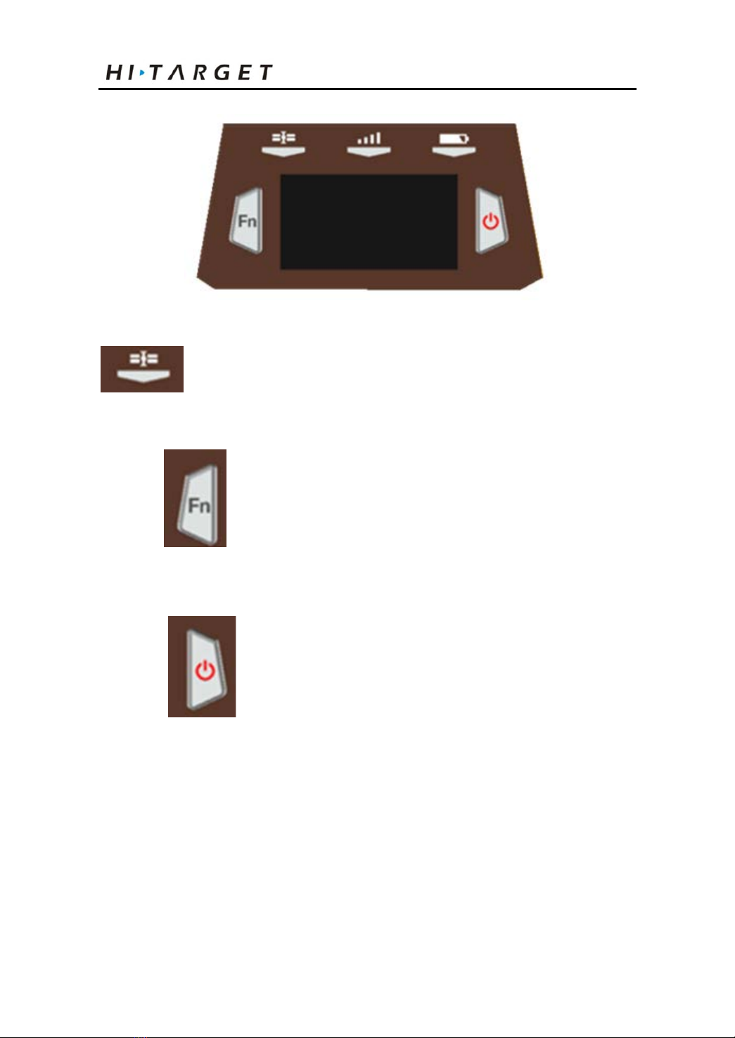
Control Panel
The control panel includes Fn key (function key), power
button, LED display and 3 indicator lights which are satellite
light, status light (bi-color light) and power light (bi-color
light). Two buttons cover all functions of V60 receiver setting.
Upper cover
Bottom cover
Guard circle
Control panel
7
Introductions to Receiver
Figure 2-2
Satellite light (green light), status light (red and
green light) and power light (red and green light)
Function key: set work mode, data link,
satellite elevation, sampling interval, reset receiver, etc.
Power button of startup & shutdown: set
confirmation and inquire current work mode.
Upper Cover
8

V60 GNSS RTK System Operation Instruction
Bottom Cover
Include battery slot, five-core socket, eight-core socket,
trumpet, etc.
Convex
plate
9

Introductions to Receiver
1. Eight-core socket and protection plug; 2. Five-core socket and protection plug; 4.
Connecting screw; 5. Battery slot; 6. Vibrating needle power socket; 7. SIM slot; 8. SD
card slot; 9.Trumpet
Figure 2-3
◇Eight-core socket: it is used to connect the receiver,
computer, handbook and external power supply, and
load and delete the data.
◇Five-core socket: it is used to connect the receiver,
external data chain and external power.
10

V60 GNSS RTK System Operation Instruction
◇Connecting screw: it is used to fasten the instrument
to base or centering rod
◇Battery slot: it is used to place lithium battery
◇Vibrating needle power socket: it is used to connect
the lithium battery and host
◇SIM card slot: when communicating with GSM data,
it is used to place SIM card.
◇SD card slot: it is used to place SD card, which can
store massive static data.
◇Trumpet: timely operate the instrument and
broadcast the status with voice
◇Protection plug: it is used to prevent dust in interface
Note: 1. If it is unnecessary to use five-core socket,
eight-core socket and difference antenna
interface, please cover the rubber plug to
prevent dust.
2. In case of inflowing, the trumpet may be
silent or hoarse, which will recover
normally after drying.
Five-core and Eight-core Sockets
Figure 2-4
11

Introductions to Receiver
Figure 2-5
1. Five-core socket: it is also called as COM2/PW2, which is
used to connect the host and external data chain, and external
power supply.
2. Eight-core socket: it is also called as COM1/USB/PW1,
which is used to connect the computer and controller, set
parameters, download and delete files.
Table 2.1 Description of five-core and eight-core socket signals
Small five-core signal
Large eight-core signal
1 Ground GND 1 Data into RXD
2 Ground GND 2 US B D-
3 Power into Vin 3 US B D+
4 Data into RXD 4 USB V+
5 Data out TXD 5 Power into Vin
6
Cable insertion mark
GC-2
7 Data out TXD
8 Ground GND
◇Symbol of cable insertion: GC-2 is cable interior
Jag
Jag
12

V60 GNSS RTK System Operation Instruction
ground
◇All round sockets are numbered anticlockwise in
positive face; all round plugs are numbered
anticlockwise in weld face.
◇All TXD and RXD are described by the receiver.
EXD is the transmit data line of receiver; RXD is
the receive data line of receiver.
◇The signal of computer serial DB9 pin joint: 2
(RXD computer data receiving signal line); 3.
(TXD computer data transmit signal line) and 5.
(GND signal earth). “2 receiving 3 sending” for
short
Note: It refers to the socket front of host bottom in
the face of host (weld face of socket).
Batteries
Positive pole
Negative pole
13

Introductions to Receiver
Figure 2-6
Environmental Requirements
The receiver shall operate in dry working environment
regardless of waterproof materials. In order to advance the
stability and service cycle of receiver, the receiver shall be
prevented fromextreme environment, such as:
◇Moisture
◇Temperatures above 65 degrees centigrade
◇Below - 40 degrees centigrade
◇Corrosive liquids or gases
Electronic Jamming
The receiver shall not be installed in the place near to strong
electric power and interference signal, such as:
◇Oil duct (spark plugs)
◇Generator
◇Battery-operated motor cycle
◇DC-AC power supply changeover equipment
◇Signal transmitting station (tower)
◇Power supply
Warning: the receiver shall be installed 1 meter away
14
Other manuals for V60
1
Table of contents
Other Hi-Target Receiver manuals

Hi-Target
Hi-Target SL300 series User manual

Hi-Target
Hi-Target V200 User manual

Hi-Target
Hi-Target V90 Plus User manual

Hi-Target
Hi-Target V100 User manual

Hi-Target
Hi-Target V60 User manual

Hi-Target
Hi-Target V90 Plus User manual

Hi-Target
Hi-Target vRTK User manual

Hi-Target
Hi-Target iRTK5 User manual

Hi-Target
Hi-Target V100 User manual

Hi-Target
Hi-Target V100 User manual


