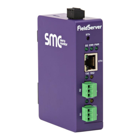
SMC Sierra Monitor FS-ROUTER-BACX User guide

Document Revision: 2.A
T18054
FieldServer
BACnet Router FS-ROUTER-BACX
Start-up Guide
BAS Router (BACnet Multi-Network Router)
APPLICABILITY & EFFECTIVITY
The instructions are effective for the above as of July 2018.

BACnet Router Start-up Guide
Contact Information
Technical Support
Please call us for any technical support needs related to the FieldServer product.
Sierra Monitor Corporation
1991 Tarob Court
Milpitas, CA 95035
Website: www.sierramonitor.com
U.S. Support Information:
+1 408 964-4443
+1 800 727-4377
Email: support@sierramonitor.com
EMEA Support Information:
+44 2033 1813 41
Email: support.emea@sierramonitor.com

BACnet Router Start-up Guide
Table of Contents
TABLE OF CONTENTS
1BACnet Router Description ................................................................................................................5
2Certification..........................................................................................................................................5
2.1 BTL Mark –BACnet Testing Laboratory.........................................................................................5
3BACnet Router Setup ..........................................................................................................................6
3.1 Mounting.........................................................................................................................................6
3.2 Dimensions.....................................................................................................................................7
3.2.1 Dimension Drawing FS-ROUTER-BAC1 ................................................................................7
3.2.1 Dimension Drawing FS-ROUTER-BAC ..................................................................................8
3.3 R2 Port Jumper Settings ................................................................................................................9
3.3.1 Bias Resistors..........................................................................................................................9
3.3.2 Termination Resistor .............................................................................................................10
3.3.3 Power Jumper Settings .........................................................................................................11
3.4 R1 Port Small DIP Switches.........................................................................................................12
4Installing the BACnet Router............................................................................................................13
4.1 RS-485 Connection R1 Port.........................................................................................................13
4.2 RS-485 Connection R2 Port.........................................................................................................13
4.3 10/100 Ethernet Connection Port .................................................................................................14
5Operation............................................................................................................................................14
5.1 Power Up the Device....................................................................................................................14
6Connecting to the BACnet Router ...................................................................................................15
6.1 Using the FieldServer Toolbox .....................................................................................................15
6.2 Using a Web Browser Directly......................................................................................................16
7Configuring the BACnet Router .......................................................................................................17
7.1 Settings.........................................................................................................................................17
7.1.1 Button Functions....................................................................................................................17
7.1.2 Network Settings ...................................................................................................................17
7.1.3 Multiple Connections.............................................................................................................17
7.1.4 BACnet/IP Primary ................................................................................................................17
7.1.5 BACnet/IP Secondary ...........................................................................................................18
7.1.6 BACnet MS/TP and BACnet Ethernet...................................................................................18
7.2 Diagnostics ...................................................................................................................................19
7.2.1 DeviceFindTM .........................................................................................................................20
7.2.1.1 Export Button .................................................................................................................20
Appendix A Useful Features....................................................................................................................21
Appendix A.1. Tooltips.............................................................................................................................21
Appendix A.2. Before Contacting Technical Support Take a Diagnostic Capture..................................22
Appendix A.3. Take a Diagnostic Capture with FS-GUI..........................................................................25
Appendix B Specifications.......................................................................................................................26
Appendix C Limited 2 Year Warranty......................................................................................................27

KNX to BACnet/IP Configuration Guide
Table of Contents
LIST OF FIGURES
Figure 1: DIN Rail..........................................................................................................................................6
Figure 2: FS-ROUTER-BAC1 .......................................................................................................................7
Figure 3: FS-ROUTER-BAC .........................................................................................................................8
Figure 4: Bias Resistor Jumper.....................................................................................................................9
Figure 5: Termination Resistor Jumper.......................................................................................................10
Figure 6: Power Jumper Switch..................................................................................................................11
Figure 7: Bias Resistor DIP Switches & EOL..............................................................................................12
Figure 8: Port 1 RS-485 Connection...........................................................................................................13
Figure 9: Port 2 RS-485 Connection...........................................................................................................13
Figure 10: Ethernet Connection..................................................................................................................14
Figure 11: Power Connection .....................................................................................................................14
Figure 12: BACnet Router Settings Page...................................................................................................16
Figure 13: BACnet Router Diagnostics Page..............................................................................................19
Figure 14: BACnet Router DeviceFindTM ....................................................................................................20
Figure 15: Ethernet Port Location...............................................................................................................22

BACnet Router Start-up Guide
Page 5 of 27
1 BACNET ROUTER DESCRIPTION
The BACnet Router provides stand-alone routing between BACnet networks such as BACnet/IP, BACnet
Ethernet, and BACnet MS/TP –thereby allowing the system integrator to mix BACnet network
technologies within a single BACnet internetwork. There are three physical communication ports on the
BAS Router. One is a 10/100 Mbps Ethernet port and the other two are RS-485 MS/TP ports.
Configuration is accomplished via a web page.
The BACnet Router is cloud ready and connects with Sierra Monitor’s SMC Cloud.
NOTE: For SMC Cloud information, refer to the SMC Cloud Start-up Guide online at the Sierra
Monitor website.
NOTE: The latest versions of instruction manuals, driver manuals, configuration manuals and
support utilities are available on the Sierra Monitor website.
2 CERTIFICATION
2.1 BTL Mark –BACnet Testing Laboratory
The BTL Mark on the BACnet Router is a symbol that indicates that a product has
passed a series of rigorous tests conducted by an independent laboratory which verifies
that the product correctly implements the BACnet features claimed in the listing. The
mark is a symbol of a high-quality BACnet product.
Go to www.BACnetInternational.net for more information about the BACnet Testing
Laboratory. Click here for the BACnet PIC Statement.

BACnet Router Start-up Guide
Page 6 of 27
3 BACNET ROUTER SETUP
3.1 Mounting
The following mounting options are available:
•Product comes with tabs for wall or surface mount. These can be snapped off if not required.
•DIN rail mounting bracket –included in the accessory kit or ordered separately (part # FS-8915-
35-QS).
WARNING: Install only as instructed, failure to follow the installation guidelines or using screws
without the DIN rail mounting bracket could result in permanent damage to the product. If the
FieldServer is removed from the DIN rail, use the original screws to reattach. Only screws
supplied by SMC should be used in the holes found on the back of the unit when attaching the
optional DIN Rail bracket. USE OF ANY OTHER SCREWS MAY DAMAGE THE UNIT.
Tab
Din Rail
Figure 1: DIN Rail

BACnet Router Start-up Guide
Page 7 of 27
3.2 Dimensions
3.2.1 Dimension Drawing FS-ROUTER-BAC1
R2 Port
Figure 2: FS-ROUTER-BAC1

BACnet Router Start-up Guide
Page 8 of 27
3.2.1 Dimension Drawing FS-ROUTER-BAC
R1 Port
R2 Port
Figure 3: FS-ROUTER-BAC

BACnet Router Start-up Guide
Page 9 of 27
3.3 R2 Port Jumper Settings
Gently remove the BACnet Router enclosure to access the jumpers on the unit.
3.3.1 Bias Resistors
The FieldServer bias resistors are used to keep the RS-485 bus to a known state, when there is no
transmission on the line (bus is idling), to help prevent false bits of data from being detected. The bias
resistors typically pull one line high and the other low - far away from the decision point of the logic.
In the RS-485 carrier, the bias resistor is 510 ohms which is in line with the BACnet spec. It should only
be enabled at one point on the bus (on the field port were there are very weak bias resistors of 100k).
Since there are no jumpers, many FieldServers can be put on network without running into the bias
resistor limit which is < 500 ohms.
NOTE: See www.ni.com/support/serial/resinfo.htm for additional pictures and notes.
Bias Resistor Jumper
Figure 4: Bias Resistor Jumper

BACnet Router Start-up Guide
Page 10 of 27
3.3.2 Termination Resistor
Termination resistors are also used to reduce noise. These pull the two lines of an idle bus together.
However, they would override the effect of any bias resistors, if connected.
Termination Resistor
Jumper
Figure 5: Termination Resistor Jumper

BACnet Router Start-up Guide
Page 11 of 27
3.3.3 Power Jumper Settings
The FieldServer Carrier Board power jumper is set to position A by default but can be changed to position
B for other power supply requirements.
Position A: The Carrier makes use of a full-wave rectifying bridge. Can be used for 12-24VAC input or
9 –30VDC input. At 9VDC this becomes marginal.
Position B: The Carrier makes use of a half-wave rectifying bridge. Best position for grounded AC
transformers and for using DC voltage down to 9VDC.
Power Jumper Switch
in position “A”
Figure 6: Power Jumper Switch

BACnet Router Start-up Guide
Page 12 of 27
3.4 R1 Port Small DIP Switches
NOTE: Only applies to FS-ROUTER-BAC models.
Gently remove the BACnet Router enclosure to access the small DIP switches for the R1 Port.
•If more than one RS-485 device is connected to the network, then the field bias resistor switch
needs to be enabled to ensure proper communication. See Figure 7 for the orientation of
switch positions referenced below.
oThe default factory setting is OFF (switch position = right side)
oTo enable biasing, turn the bias switch ON (switch position = left side)
NOTE: Biasing only needs to be enabled on one device. The BACnet Router has 510 ohm
resistors that are used to set the biasing.
•If the FieldServer is the last device on the trunk, then the end of line (EOL) termination switch
needs to be enabled. See Figure 7 for the orientation of switch positions referenced below.
oThe default factory setting is OFF (switch position = right side)
oTo enable the EOL termination, turn the EOL switch ON (switch position = left side)
Figure 7: Bias Resistor DIP Switches & EOL
Bias Resistor Switch
End of Line Switch

BACnet Router Start-up Guide
Page 13 of 27
4 INSTALLING THE BACNET ROUTER
NOTE: Only the 2 port FS-ROUTER-BAC model BACnet Router utilizes the R1 port.
4.1 RS-485 Connection R1 Port
Connect to the 3-pin connector as shown.
The following Baud Rates are supported on the R1 Port:
9600, 19200, 38400, 57600, 76800, 115200
4.2 RS-485 Connection R2 Port
Connect to the 3 pins on the left-hand-side of the 6 pin connector as shown.
The following Baud Rates are supported on the R2 Port:
9600, 19200, 38400, 57600, 76800, 115200
Figure 8: Port 1 RS-485 Connection
Figure 9: Port 2 RS-485 Connection
+ - GND
B+ A- SG

BACnet Router Start-up Guide
Page 14 of 27
4.3 10/100 Ethernet Connection Port
The Ethernet Port is used both for BACnet Ethernet and BACnet/IP communications. It is also used for
configuring the router from a Web page.
Connect the router to a BACnet network and optionally to a PC for configuration purposes via an Ethernet
cable between the PC and the BACnet Router or connect the BACnet Router and the PC to the switch
using a straight CAT5 cable.
5 OPERATION
5.1 Power Up the Device
Apply power to the device. Ensure that the power supply used complies with the specifications provided
in Appendix B. Ensure that the cable is grounded using the “Frame GND” terminal. The BACnet Router
is factory set for 9-30VDC or 12-24VAC.
Ethernet
Port
Figure 11: Power Connection
PWR+ PWR- FG
Figure 10: Ethernet Connection

BACnet Router Start-up Guide
Page 15 of 27
6 CONNECTING TO THE BACNET ROUTER
The FieldServer Toolbox Application can be used to discover and connect to the BACnet Router on a
local area network. To connect to the BACnet Router over the Internet using Toolbox, add the Internet
exposed IP Address of the Router by clicking on the button, or alternatively enter the Internet
exposed IP Address in a web browser directly.
6.1 Using the FieldServer Toolbox
•Install the FS Toolbox application from the USB drive or download it from SMC’s website.
•Use the FS Toolbox application to find the BACnet Router, change the IP Address details if
required and launch the Web Configurator.
+

BACnet Router Start-up Guide
Page 16 of 27
6.2 Using a Web Browser Directly
•Open a Web Browser and connect to the BACnet Router’s Default IP Address. The Default IP
Address of the BACnet Router is 192.168.2.101, Subnet Mask is 255.255.255.0.
•If the PC and the BACnet Router are on different IP Networks, assign a Static IP Address to the
PC on the 192.168.2.X network.
NOTE: The FieldPoP™ tab (see Figure 12) allows users to connect to the SMC Cloud,
Sierra Monitor’s device cloud solution for IIoT. The SMC Cloud enables secure remote
connection to field devices through a FieldServer and its local applications for
configuration, management, maintenance. For more information about the SMC Cloud,
refer to the SMC Cloud Start-up Guide.
Figure 12: BACnet Router Settings Page

BACnet Router Start-up Guide
Page 17 of 27
7 CONFIGURING THE BACNET ROUTER
7.1 Settings
7.1.1 Button Functions
•Save –write the currently displayed settings to the device. A
restart will be required to apply the updated settings.
•Reload –discard the currently displayed settings and reload
the settings stored on the device. This will undo any unsaved
edits.
•Defaults –discard the currently displayed settings and load
default settings. This must still be saved and the device must
be restarted for the default settings to be applied.
•Restart –restarts the device.
7.1.2 Network Settings
The IP settings for the router are also used by both BACnet/IP
connections. The IP settings can be changed in the Network
Settings section as shown.
7.1.3 Multiple Connections
•Network Number –set up the BACnet network number for the connection. Legal values are
1-65534. Each network number must be unique across the entire BACnet internetwork.
•Enable –enable or disable the connection; note that BACnet/IP Primary is always enabled.
7.1.4 BACnet/IP Primary
•Device Instance and Device Name –a BACnet Router must
provide a Device Object. Configure its name and Instance
Number here. Take care to select a Device Instance Number that
is unique across the entire BACnet internetwork.
•IP Port –the BACnet/IP default is 47808 (0xBAC0), but a different
port number may be specified here.

BACnet Router Start-up Guide
Page 18 of 27
7.1.5 BACnet/IP Secondary
•Enable BBMD –select this checkbox to enable the Router to
act as a BBMD.
•IP Port –this MUST be different to the IP Port used on the
BACnet/IP Primary connection. Default is 47809 (0xBAC1).
•Public IP Address and Port –if the BBMD is being accessed
across a NAT Router, then these values must be configured
with the public IP Address and Port by which the BBMD can be
reached from across the NAT Router. The Public IP Address
and Port would also be used in the BDT of remote BBMD's that
need to reach this BBMD across the NAT Router. If no NAT
Router is being used, these fields can be left blank. For
example, type into a Google browser “my IP Address” to see
the local PC’s Public IP Address.
7.1.6 BACnet MS/TP and BACnet Ethernet
•Max Info Frames –the number of transactions the
Router may initiate while it has the MS/TP token.
Default is 50.
•Max Master –the highest MAC address to scan for
other MS/TP master devices. The default of 127 is
guaranteed to discover all other MS/TP master
devices on the network.
•MAC Address –legal values are 0 to 127, must be
unique on the physical network.
•Baud Rate –the serial baud rate used on the
network.
•Token Usage Timeout (ms) –the number of
milliseconds the router will wait before deciding that
another master has dropped the MS/TP token. This
value must be between 20ms and 100ms. Choose a
larger value to improve reliability when working with
slow MS/TP devices that may not be able to meet
strict timing specifications.

BACnet Router Start-up Guide
Page 19 of 27
7.2 Diagnostics
By clicking on the Diagnostics tab all the connection communication details can be viewed to ensure the
BACnet Router is working correctly.
Figure 13: BACnet Router Diagnostics Page

BACnet Router Start-up Guide
Page 20 of 27
7.2.1 DeviceFindTM
The diagnostics page offers a DeviceFindTM function for listing BACnet devices that are visible to the
router. A configurable Who-Is broadcast is sent out when the 'Start' button is pressed, and I-Am
responses received back from the field are listed, along with the name of the router port by which each
device can be reached.
DeviceFindTM is limited to 300 devices. There may be more devices on a large BACnet network, and the
Who-Is request can be limited to devices of interest by configuring discovery parameters.
The following fields exist for configuring the Who-Is broadcast (all are optional):
•Low Device Instance –sets a low limit for the Device Instance. Devices with a lower instance
number will ignore the Who-Is request.
•High Device Instance –sets a high limit for the Device Instance. Devices with a higher instance
number will ignore the Who-Is request.
•Network –broadcasts the Who-Is request only on the BACnet network segment with the
specified network number. This depends on the router being able to find the specified network.
DeviceFindTM is performed by the device object configured on the router. Since this device is bound
locally to the BACnet/IP Primary segment, all devices present on this BACnet segment will appear as
local devices with network number 0. Also, to discover only the devices present on this BACnet segment,
set the Network parameter to 0.
7.2.1.1 Export Button
This button appears when some devices have been discovered. The user may click this button to save
the list of discovered devices to a file called "BACnet Devices.csv".
Figure 14: BACnet Router DeviceFindTM
Table of contents
Other SMC Sierra Monitor Network Router manuals
