SME M2-9R Series User manual
The best pick
-
up arm in the world
INSTRUCTIONS
SERIES M2 MODELS M2
-
9R & M2
-
12R
SERIES M2-9R & M2-12R
INSTRUCTIONS

2
Introduction
SME is an iconic brand founded in 1946 by audio
legend Alastair Robertson-Aikman in West Sussex,
England. Today SME is recognised as makers of
the nest precision turntables and tonearms in
the world. Entirely made in-house by state of the
art manufacturing processes, complemented by
traditional craftsmanship methods.
SME audio has evolved from 75 years of engineering
excellence, innovation and perfection delivering
precise and pure audio reproduction.
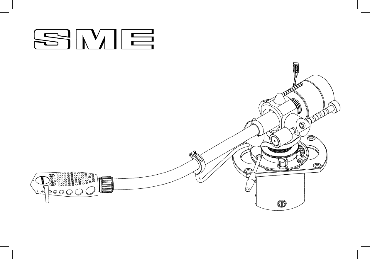
The SME M2-9R and M2-12R tonearms are of
meticulous build quality with all the most important
features including lightweight stainless steel tonearm
tube, detachable aluminium headshell with double
draw pins for extra rigidity and azimuth adjustment,
tungsten balance weight, high quality ball race
bearings in all planes and a level of stiffness to suit
a wide range of cartridges.

3
Contents
Page
2 Introduction
4 General Arrangement
5 Dimensions
6 Specications
7 Packing List
8 Parts Identication
9 Preparing Mounting Board
10 Fitting the Tonearm
11 Audio Lead
12 Fitting the Cartridge
13 Fitting the Headshell
14 Longitudinal Balance
15 Vertical Tracking Force (VTF) Adjustment
16 Arm Height (VTA) Adjustment
17 Azimuth Adjustment
18 Horizontal Tracking Angle (HTA) Adjustment
19 Positioning the Armrest
20 Anti-skate Adjustment
21 Operation
22 Adjusting and Cleaning the Arm Lift
23 Appendix
General Arrangement
4
4
General Arrangement

5
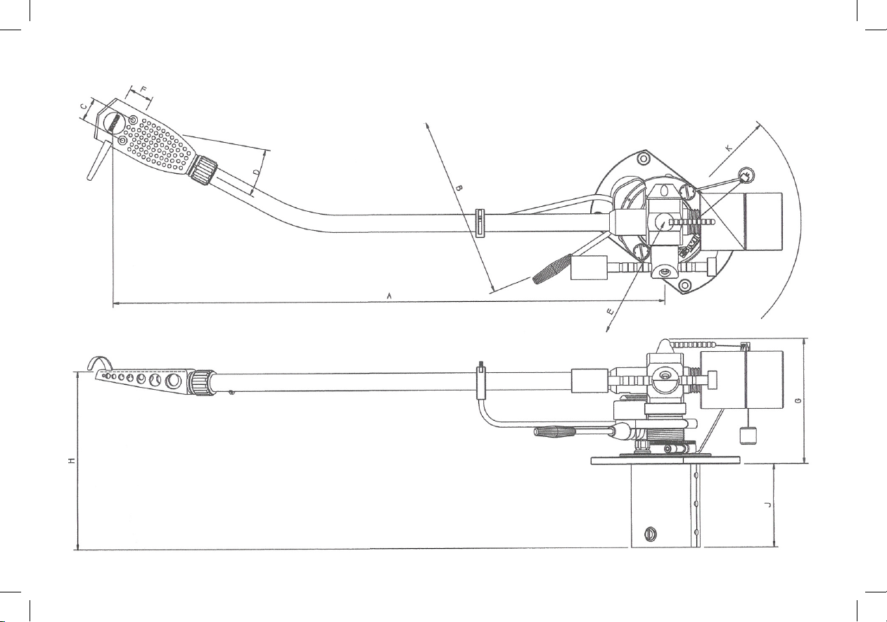
Dimensions
M2-9R M2-12R
A - Pivot to Stylus 233.20 308.81
B - Pivot to Turntable Centre 215.40 295.60
C - Cartridge Fixing Centres 12.70 12.70
D - Offset Angle 23.63º 17.62°
E - Linear Offset 93.47 93.47
F - Overhang 17.80 13.21
G - Height above Mounting Surface 87.00 max 87.00 max
63.00 min 63.00 min
H - Mounting Surface to Underside of Headshell 67.40 max 67.40 max
43.40 min 43.40 min
J - Depth below Mounting Surface 46.00 46.00
K - Balance Weight Radial Clearance 79.00 85.00

6
Specications
M2-9R M2-12R
Effective Mass 9.5g 18g
Cartridge Balance Range
Headshell: up to 38g 38g
Plug-heads: up to 46g 46g
Vertical Tracking Force (VTF) 5g 5g
Maximum Tracking Error (degree/mm) 0.013mm 0.010mm
Null Points: Inner (mm radii) 66.04mm 66.04mm
Outer (mm radii) 120.9mm 120.90mm
Weight, net (g) 735mm 834mm
Audio Lead: 1.2m long balanced hybrid cable
with gold plated phono plug
connections to amplier and
independent ground system
Internal Wiring: Silver Litz
Output: RCA Phono

7
Packing List
Series M2-9R or M2-12R Precision Tonearm
Detachable Headshell
Instruction Book
Mounting Template
Alignment Protractor
Headshell Hardware……… Cartridge Screws/Nuts (alloy)
2mm Hex Wrench
0.89mm Hex Wrench
Mounting Hardware……… Set of M3 x 20mm Button Head Screws
4 Nuts and 4 Washers
4 Tonearm Mounting Washers
2.5mm Hex Wrench
Audio Lead
Bias Weight
Bias Guide
Guarantee Card
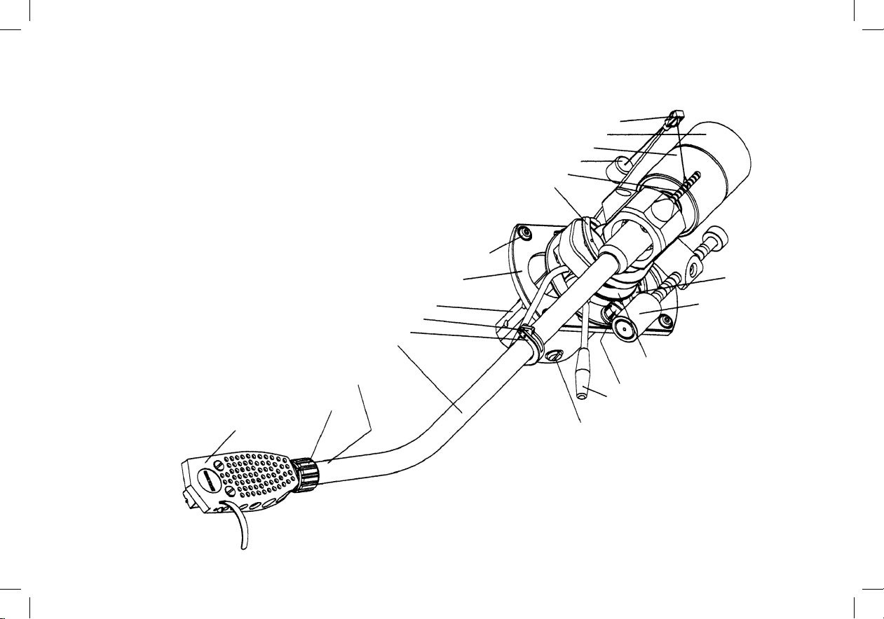
Parts Identification
Anti
-Skate Guide
Accessory Balance Weight
Balance Weight
Anti
-Skate Weight
Anti
-Skate Lever
Arm Lift
M3 Button Head Mounting Screw
& Arm Mounting Washer
Bedplate
Shield Can
Arm Rest Catch
Arm
Rest
Tonearm
Azimuth Locking Screw
underside tonearm at this point
Arm Socket Nut
Detachable Headshell
Ground Terminal
Control Lever
Base Clamp Nut & Washer
VTA Thumbwheel
Wayrod/Rider Weight
Pillar Clamp Screw
8
Parts Identication
912/101 Preparing the arm mounting Board
Where the deck is not already cut to accept an
SME arm, it will need to be prepared as follows:
Pierce the centre point A of the mounting
template to accept a pin or needle about 50mm
long. Place the template on the record spindle
and keeping it parallel with the surface on which
the arm will be mounted pass the pin vertically
through the centre point A and spike it into the
pick-up arm mounting board.
912/102
Disengage the template from the spindle and
maintaining the same alignment slide it down the
pin and onto the mounting board. This will
position the base for maximum effective
movement when adjusting the horizontal
tracking angle (HTA), see 125. Anti-clockwise
rotation from this position up to approximately
40° can be made to meet individual needs but is
not critical provided that the requirements of the
alignment protractor can be satisfied. Note that
the rear overhang requires a 51mm radial
clearance from the point shown on the template.
912/103
Using a scriber or a compass point, spike
through the centre points B and centres of the
four fixing holes. Remove the template and mark
two Ø28mm circles about the points B already
centred. Join these together tangentially with
two parallel lines to complete marking out.
Drill four Ø4mm fixing holes and two Ø28mm
holes. Cut away the remaining area to form a
slot and finish the edges with a file and
glasspaper. If a hole saw is not available chain
drill a series of small holes around the inside of
the line, saw and file out.
With suitable tools and technique the procedure
is similar for materials other than wood.
9
9
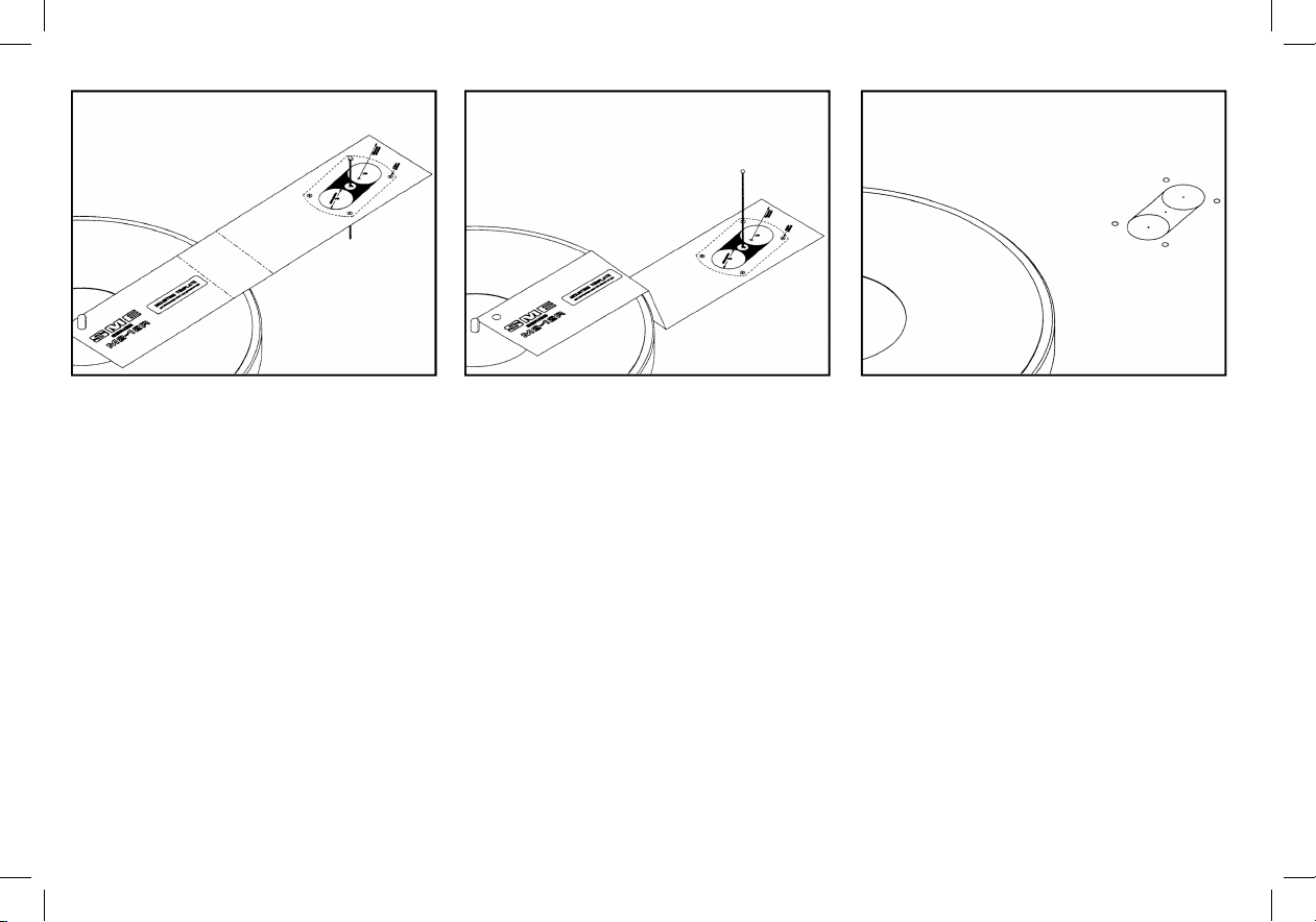
Preparing the Mounting Board
Where the deck is not already cut to accept an
SME tonearm, it will need to be prepared
as follows:
Pierce the centre point A of the mounting
template to accept a pin or needle about 50mm
long. Place the template on the record spindle
and keeping it parallel with the surface on which
the arm will be mounted pass the pin vertically
through the centre point A and spike it into the
tonearm mounting board.
Disengage the template from the spindle and
maintaining the same alignment slide it down the
pin and onto the mounting board. This will position
the base for maximum effective movement
when adjusting the horizontal tracking angle
(HTA). Anti-clockwise rotation from this position
up to approximately 40° can be made to meet
individual needs but is not critical provided that
the requirements of the alignment protractor can
be satised. Note that the rear overhang requires
a 51mm radial clearance from the point shown on
the template.
Using a scriber or a compass point, spike
through the centre points B and centres of the
four xing holes. Remove the template and mark
two Ø28mm circles about the points B already
centred. Join these together tangentially with two
parallel lines to complete marking out.
Drill four Ø4mm xing holes and two Ø28mm
holes. Cut away the remaining area to form a slot
and nish the edges with a le and glasspaper.
If a hole saw is not available chain drill a series
of small holes around the inside of the line, saw
and le out.
With suitable tools and technique the procedure is
similar for materials other than wood.

912/104 Fitting the arm
Remove the inner base clamp nut and base
clamp washer. Pass the loop at the lower end
of the anti-skate guide over the base clamp bolt
and fit the base clamp washer. Ensure that the
loop on the anti-skate guide is fitted into the
counterbore in the underside of the washer and
the slot is aligned with the anti-skate guide.
Replace the base clamp nut and tighten, lightly.
912/105
Fit a mounting washer to each of the four
counterbores in the upper surface of the
bedplate.
912/106
Position the arm on the mounting board and
insert the M3 button head screws into the holes.
If the holes are not tapped M3 to accept the
screws directly, it will be necessary to fit the nuts
and washers under the board. Tighten fully
using the 2.0mm A/F wrench.
10
10
Fitting the Tonearm
Remove the inner base clamp nut and base
clamp washer. Pass the loop at the lower end of
the anti-skate guide over the base clamp bolt and
t the base clamp washer. Ensure that the loop on
the anti-skate guide is tted into the counterbore
in the underside of the washer and the slot is
aligned with the anti-skate guide. Replace the
base clamp nut and tighten, lightly.
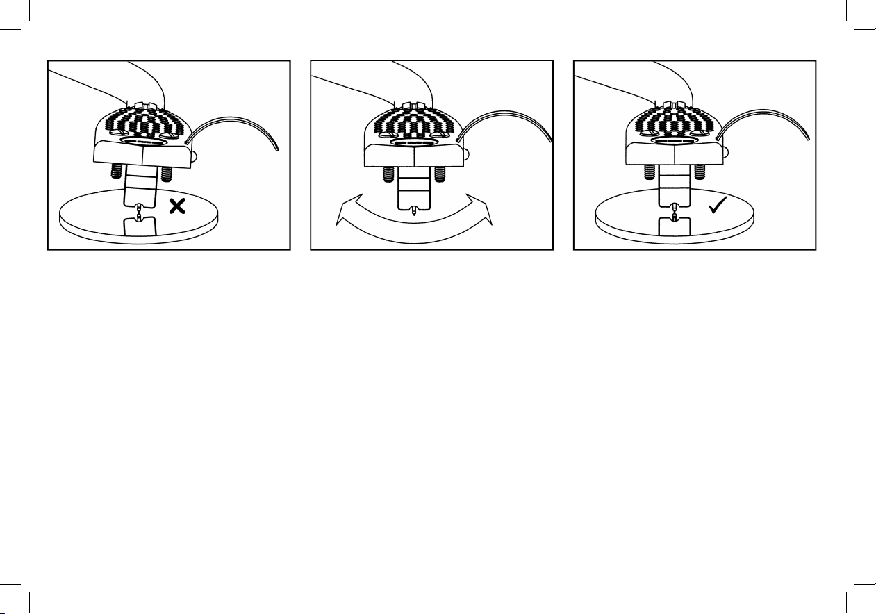
Fit a mounting washer to each of the four
counterbores in the upper surface of the bedplate.
Position the tonearm on the mounting board and
insert the M3 button head screws into the holes. If
the holes are not tapped M3 to accept the screws
directly, it will be necessary to t the nuts and
washers under the board. Tighten fully using the
2mm wrench.
11
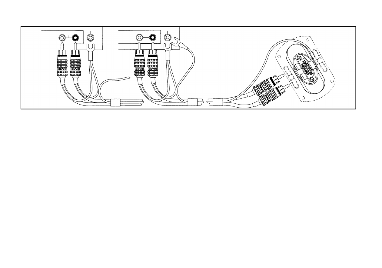
NOTE:
Connection should be made between
the ground terminals of the deck and
pre-amp unless a path already exists.
GND
GND
MC HEAD AMPLIFIER
/TRANSFORMER
PRE-AMPLIFIER
/CONTROL UNIT
L PHONO R
L PHONO R
912/107 Audio Lead
The illustration shows use with and without a head amp/transformer and phono plug connections should be made accordingly.
Connect the ground wire serving the arm to the pre-
amp ground, and those from the rear of the phono plugs to the ground terminal on the piece of
equipment to which these plugs are connected.
If the turntable has a ground terminal, it too should be connected to the pre-amp ground, provided it is not already grounded by another path.
The system has been designed for a high signal to noise ratio and if this is not achieved multiple ground paths or the over p
roximity of mains equipment will
be likely causes. Some cartridges have an external foil tag connecting the right channel ground terminal to the cartridge body. For use in
a metal shell it will
be necessary to remove this with a small pair of tweezers or the point of a blade, lifting the tag off over
the terminal pin. If this is not done a ground loop
may be formed, causing hum on the right channel.
CONNECT TO PRE-
AMPLIFIER
GROUND
11
Audio Leads
The illustration shows use with and without a head amp/transformer and phono plug connections should be made accordingly.
Connect the ground wire serving the tonearm to the pre-amp ground and those from the rear of the phono plugs to the ground terminal on the piece of
equipment to which these plugs are connected.
If the turntable has a ground terminal, it too should be connected to the pre-amp ground, provided it is not already grounded by another path.
The system has been designed for a high signal to noise ratio and if this is not achieved multiple ground paths or the over proximity of mains equipment will
be likely causes. Some cartridges have an external foil tag connecting the right channel ground terminal to the cartridge body. For use in a metal shell it will
be necessary to remove this with a small pair of tweezers or the point of a blade, lifting the tag off over the terminal pin. If this is not done a ground loop may
be formed, causing hum on the right channel.
912/108 Fitting the cartridge
See 912/113 - Removing the headshell.
Before fitting the cartridge see that the stylus
guard (not illustrated) is in position as a
precaution against accidental damage.
The cartridge leads have Ø1.2mm receptacles
to suit the cartridge. These may require
adjustment with pliers or a screwdriver blade for
a snug fit on non-standard terminals.
Connections to the cartridge must never be
made by direct soldering.
The coding is as follows:
Red - right channel signal
Green - right channel signal ground
White - Left channel signal
Blue - Left channel signal ground
912/109
Most cartridges are supplied with their own
screws. We provide one pair #3-48 UNC x 11mm
with nuts and washers, other lengths are
available direct.
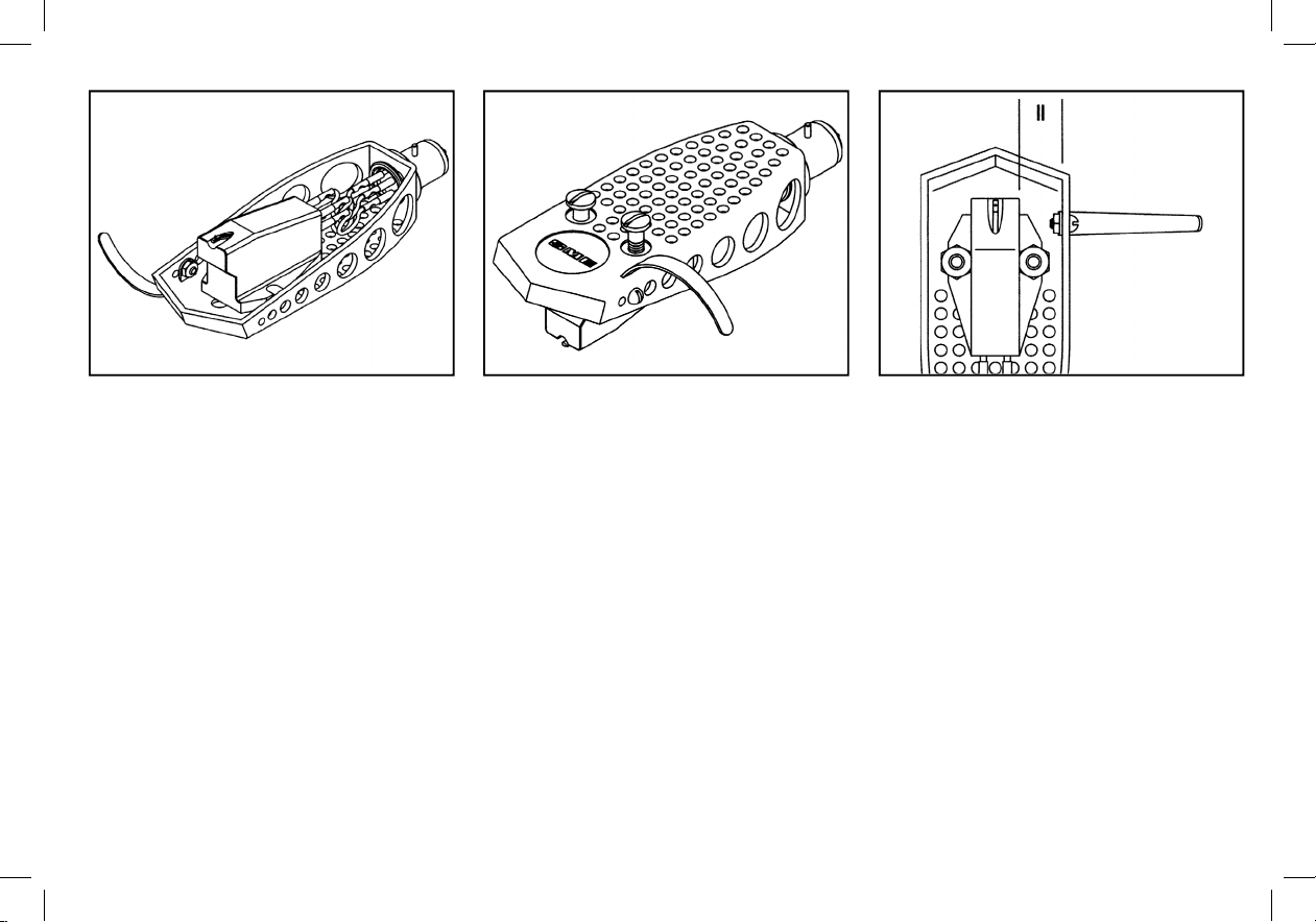
912/110
Examine the top of the cartridge. It is important
that it presents a good flat face to the underside
of the headshell. Before final tightening check
that the cartridge is lying parallel to the
reference edge of the headshell, as shown.
Tighten the fixing screws securely using a
screwdriver, which must be a good fit in the
screw slots to avoid damage. Hold the nut if
necessary to prevent rotation.
The screws are non-magnetic. Damage can be
caused if a screw is snatched by magnetic
attraction whilst being offered up to the
cartridge. For the same reason do not lay down
tools nearby.
12
12
Fitting the Cartridge
Before tting the cartridge see that the stylus
guard (not illustrated) is in position as a precaution
against accidental damage.
The cartridge leads have Ø1.2mm receptacles to
suit the cartridge.
The coding is as follows:
Red - Right Channel Signal
Green - Right Channel Signal Ground
White - Left Channel Signal
Blue - Left Channel Signal Ground
Most cartridges are supplied with their own
screws. We provide one pair #3-48 UNC x
11mm with nuts and washers, other lengths are
available from SME.
Examine the top of the cartridge. It is important
that it presents a good at face to the underside
of the headshell. Before nal tightening check that
the cartridge is lying parallel to the reference edge
of the headshell, as shown.
Tighten the xing screws securely using a
screwdriver, which must be a good t in the screw
slots to avoid damage. Hold the nut if necessary
to prevent rotation.
The screws are non-magnetic. Damage can
be caused if a screw is snatched by magnetic
attraction whilst being offered up to the cartridge.
For the same reason do not lay down tools nearby.

912/111 Cartridge lead replacement
The cartridge leads. Part No. 1806, can be
replaced and may be obtained from your dealer
or direct.
They should be fitted according to the colour
coding shown looking onto the shell from the
front.
912/112 Fitting the headshell
Insert the S2-R headshell into the arm socket
and press firmly inwards until the draw pins
contact the thread of the socket nut. Maintaining
pressure, turn the socket nut anti-clockwise
viewed from the front to draw the headshell
home. It should be tightened firmly but not to the
point of strain.
912/113 Removing the headshell
Removal is the reverse of fitting. Holding the
headshell firmly to prevent rotation turn the
socket nut, clockwise when viewed from the
front, until the headshell is completely released.
Take care to avoid damaging the cartridge
during this operation.
13
WHITE
BLUE
GREEN
RED
13
Cartridge Lead Replacement
The cartridge leads can be replaced and are
available from SME.
They should be tted according to the colour
coding shown looking onto the headshell from the
front.
Fitting the Headshell
Insert the headshell into the tonearm socket and
press rmly inwards until the draw pins contact
the thread of the socket nut. Maintaining pressure,
turn the socket nut anti-clockwise viewed from the
front to draw the headshell home. It should be
tightened rmly but not to the point of strain.
Removing the Headshell
Removal is the reverse of tting. Holding the
headshell rmly to prevent rotation turn the socket
nut, clockwise when viewed from the front, until
the headshell is completely released.
Take care to avoid damaging the cartridge during
this operation.
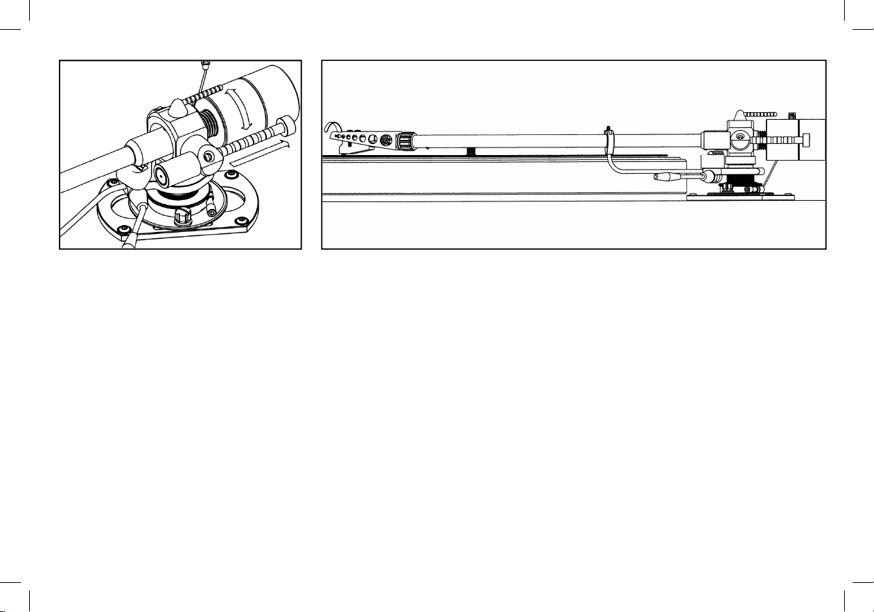
912/114 Longitudinal balance
With only the main balance weight fitted,
cartridges up to 16g may be balanced. However
by removing the balance weight end cap and
coupling the accessory balance weight (as
illustrated) cartridges up to 38g, mounted in the
S2-R headshell or plug in heads up to 46g can
be catered for.
Slide the wayrod/rider weight into the rearmost
zero position and balance the arm by rotating
the balance weight in the required direction.
Remove the accessory balance weight, when
needed, by unscrewing anti-clockwise from the
balance weight. Replace the balance weight
end cap.
14
12/115
Adjust until the arm, with the cartridge fitted,
is either level or slightly low at the front end.
14
Longitudinal Balance
With only the main balance weight tted,
cartridges up to 16g may be balanced. However
by removing the balance weight end cap and
coupling the accessory balance weight (as
illustrated) cartridges up to 38g, mounted in the
headshell or plug in heads up to 46g can be
catered for.
Slide the wayrod/rider weight into the rearmost
zero position and balance the arm by rotating the
balance weight in the required direction.
Remove the accessory balance weight, when
needed, by unscrewing anti-clockwise from the
balance weight. Replace the balance weight end
cap.
Adjust until the tonearm, with the cartridge tted, is either level or slightly low at the front end.
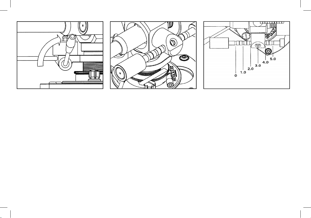
912/116 Vertical tracking force (VTF)
adjustment
For safety the lever of the lowering control
should now be moved in to the raised position.
912/117
VTF is set after longitudinal balancing has been
completed, see 912/114
It is applied by moving the complete Wayrod
assembly forward as indicated. The assembly is
calibrated to provide a maximum of 5.0g VTF in
1.0g increments between the indent positions.
Position shown is the setting for 3.0g VTF.
912/118
Half gram settings are indicated by the shallow
grooves alternating with the indent positions.
.
15
15
Vertical Tracking Force (VTF) Adjustment
For safety the lever of the lowering control should
now be moved into the raised position.
VTF is set after longitudinal balancing has been
completed.
It is applied by moving the complete wayrod
assembly forward as indicated. The assembly is
calibrated to provide a maximum of 5.0g VTF in
1.0g increments between the indent positions.
Position shown is the setting for 3.0g VTF.
Half gram settings are indicated by the shallow
grooves alternating with the indent positions.

912/119 Arm height (VTA) adjustment
Release the pillar clamp screw, using the 2mm
A/F wrench, by one turn only.
Rotate the VTA thumbwheel clockwise to
increase the height of the tonearm relative to
the base
To lower the tonearm turn the VTA thumbwheel
anti-clockwise. Finger pressure may be
required to move the arm downwards until it
stops on the arm base, at which point further
movement in either direction can be made as
necessary.
912/120
Use an old but unwarped record for the following
procedures in case of accidental damage.
Place the arm about halfway across the record
and move the control lever forward to lower it into
the playing position.
The top of the cartridge is normally the horizontal
datum; correctly fitted it will be parallel with the
tonearm.
Measure the distance from the surface of the
record to the top of the tonearm tube at the front
end using a small non-metallic ruler.
912/121
Repeat the measurement towards the rear of the
tonearm tube and compare it with first one.
Adjust the arm height with the VTA thumbwheel
until similar readings are obtained indicating that
the arm is level with the surface of the record.
Re-lock the pillar clamp screw, view the arm in
the playing position and re-adjust as necessary.
16
16
Arm Height (VTA) Adjustment
Release the pillar clamp screw, using the 2mm
wrench, by one turn only.
Rotate the VTA thumbwheel clockwise to increase
the height of the tonearm relative to the base.
To lower the tonearm turn the VTA thumbwheel
anti-clockwise. Finger pressure may be required
to move the arm downwards until it stops on the
arm base, at which point further movement in
either direction can be made as necessary.
Use an old but unwarped record for the following
procedures in case of accidental damage.
Place the arm about halfway across the record
and move the control lever forward to lower it into
the playing position.
The top of the cartridge is normally the horizontal
datum; correctly tted it will be parallel with the
tonearm.
Measure the distance from the surface of the
record to the top of the tonearm tube at the front
end using a small non-metallic ruler.
Repeat the measurement towards the rear of the
tonearm tube and compare it with rst one. Adjust
the tonearm height with the VTA thumbwheel until
similar readings are obtained indicating that the
tonearm is level with the surface of the record.
Re-lock the pillar clamp screw, view the tonearm
in the playing position and re-adjust as necessary.
912/122 Azimuth adjustment
Place a small mirror on the turntable and rest
the stylus on it. Viewed in this way any
departure from vertical is accentuated and
easily visible.
912/123
Release the azimuth locking screw underneath
the tonearm, just to the rear of the arm socket
nut. The stylus must be kept clear of the mirror
whilst this is done.
Hold the headshell firmly close to the tonearm
with one hand and twist it in the required
direction holding the tonearm firmly with the
other. The stylus must remain clear of the mirror
at all times during this operation.
Movement of the socket in the end of the
tonearm is limited by the locking screw.
912/124
Re-check with the mirror and when satisfied
lightly re-lock the screw underneath the tonearm.
17
17
Azimuth Adjustment
Place a small mirror on the turntable and rest the
stylus on it. Viewed in this way any departure from
vertical is accentuated and easily visible.
Release the azimuth locking screw underneath
the tonearm, just to the rear of the tonearm socket
nut. The stylus must be kept clear of the mirror
whilst this is done.
Hold the headshell rmly close to the tonearm
with one hand and twist it in the required direction
holding the tonearm rmly with the other. The
stylus must remain clear of the mirror at all times
during this operation.
Movement of the socket in the end of the tonearm
is limited by the locking screw.
Re-check with the mirror and when satised
lightly re-lock the screw underneath the tonearm.

912/125 Horizontal tracking angle (HTA)
adjustment
Place the tonearm into the armrest and release
the two base clamp nuts, using a snugly fitting
screwdriver.
Move the base on the bedplate as far forward
as it will go.
912/126
With a record on the turntable and having pierced
the alignment protractor for the stylus, place it on
the turntable spindle. Check that the VTF has
been set to suit the cartridge in use. Move the
arm out of the armrest and place it so that the
stylus enters the point where the alignment
protractor has been pierced. The protractor
provides two null points, the inner at 66.0mm and
the outer at 121.0mm radius. Move the base on
the bedplate until the cartridge and headshell
appear symmetrical with the lines on the
protractor at the inner point.
Inaccuracy is shown and the arrow indicates the
direction of movement required to correct it.
912/127
Similarly check the outer point and adjust the
arm until the conditions shown in the illustration
above are met.
Firmly re-lock the outer base clamp nut only.
18
18
Horizontal Tracking Angle (HTA)
Adjustment
Place the tonearm into the armrest and release
the two base clamp nuts, using a snugly tting
screwdriver.
Move the base on the bedplate as far forward as
it will go.
With a record on the turntable and having pierced
the alignment protractor for the stylus, place it
on the turntable spindle. Check that the VTF has
been set to suit the cartridge in use. Move the
tonearm out of the armrest and place it so that
the stylus enters the point where the alignment
protractor has been pierced. The protractor
provides two null points, the inner at 66mm and
the outer at 121mm radius. Move the base on the
bedplate until the cartridge and headshell appear
symmetrical with the lines on the protractor at the
inner point.
Inaccuracy is shown and the arrow indicates the
direction of movement required to correct it.
Similarly check the outer point and adjust
the tonearm until the conditions shown in the
illustration above are met.
Firmly re-lock the outer base clamp nut only.
912/128 Positioning the armrest
Release the pillar clamp screw, using the 2mm
A/F wrench.
Height adjustment will be maintained by the
VTF thumbwheel.
19
912/129
Rotate the pillar to position the
armrest conveniently in relation to the turntable. The dimension ‘X’
should not be more than 110mm or less than 50mm.
Tighten the pillar clamp screw firmly, avoiding excessive force.
19
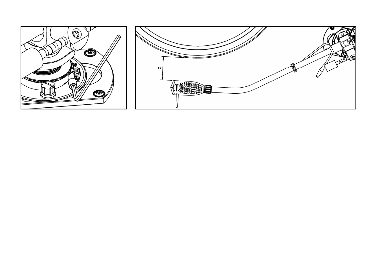
Positioning the Armrest
Release the pillar clamp screw, using the 2mm
wrench.
Height adjustment will be maintained by the VTF
thumbwheel.
Rotate the pillar to position the armrest conveniently in relation to the turntable. The dimension ‘X’
should not be more than 110mm or less than 50mm.
Tighten the pillar clamp screw rmly, avoiding excessive force.
912/130 Anti-skate adjustment
Thread the filament through guide pulley
housing and pass the loop over the anti-skate
lever.
912/131
Drop the loop into the groove corresponding to
the vertical tracking force being used.
Anti-skating is always a matter of compromise.
The values indicated are a good starting point.
Note how the stylus enters the run-in groove.
‘Snatch’ would indicate the need for a lower
value.
912/132
Loosen the inner base clamp nut enough to
allow movement of the anti-skate guide. Position
the guide so that the filament is approximately
90
o
to the anti-skate lever when the stylus is over
the outer groove of a twelve inch record. Firmly
relock the base clamp nut. Rotate the guide
pulley housing to align it with the filament, which
must lie in the groove of the pulley.
20
20
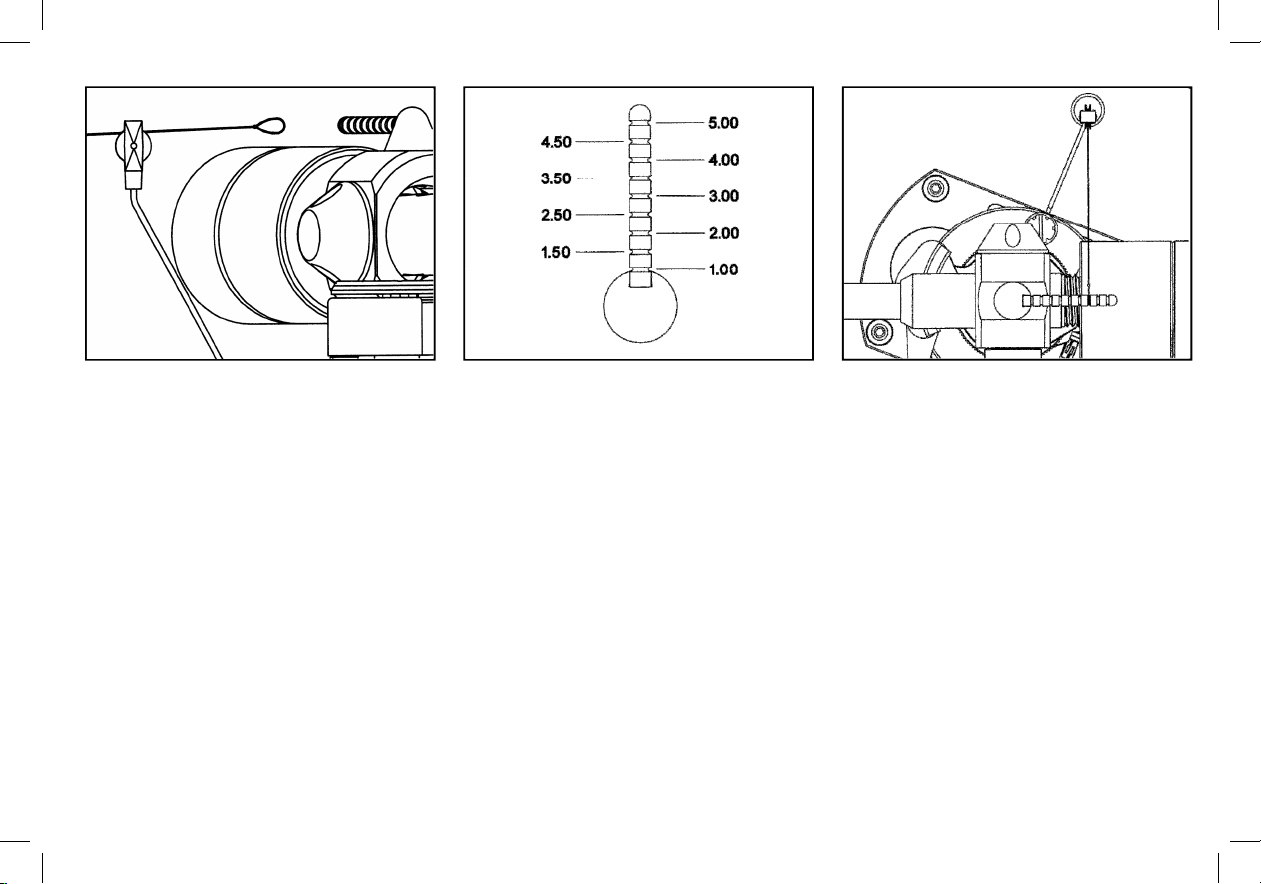
Anti-skate Adjustment
Thread the lament through guide pulley housing
and pass the loop over the anti-skate lever.
Drop the loop into the groove corresponding to
the vertical tracking force being used.
Anti-skating is always a matter of compromise.
The values indicated are a good starting point.
Note how the stylus enters the run-in groove.
‘Snatch’ would indicate the need for a lower value.
Loosen the inner base clamp nut enough to allow
movement of the anti-skate guide. Position the
guide so that the lament is approximately 90˚
to the anti-skate lever when the stylus is over
the outer groove of a twelve inch record. Firmly
relock the base clamp nut. Rotate the guide pulley
housing to align it with the lament, which must lie
in the groove of the pulley.
This manual suits for next models
1
Table of contents
Other SME Accessories manuals


Popular Accessories manuals by other brands

CASUALPLAY
CASUALPLAY saco instructions

Rittal
Rittal 7030.430 Installation and Short User Guide

GE
GE WR72X10313 Install instructions

Philips
Philips DLA67006D brochure

Black Diamond Equipment
Black Diamond Equipment HELIO 180 INSTALLATION, USE AND MAINTENANCE GUIDEBOOK

river systems
river systems EggTech series user manual


